Transient Response Analysis and Modelling of Elevating
Screw for Radial Drilling Machine
Aye Myint Kyi1, Ei Ei Htwe2, Wai Phyo Maung3
*
Department of Mechanical Engineering, Mandalay Technological University
**
Department of Mechanical Engineering, Mandalay Technological University
***
Department of Mechanical Engineering, Mandalay Technological University
DOI: 10.29322/IJSRP.8.10.2018.p8282 http://dx.doi.org/10.29322/IJSRP.8.10.2018.p8282
Abstract-The purpose of this study was to analyze the dynamic behavior of elevating screw subjected to time-varying excitation. Transient analysis is performed to know the response characteristics under the rated load of elevating screw. The effect of this vibration varies with time as the nut moves. This paper researched the elevating screw and built the elevating screw model with SolidWorks software. Modal analysis is carried out for identifying the natural frequencies and the transient analysis is applied for obtaining displacement, velocity and acceleration depend on time variation. The first step of this work is used to analyze the natural frequency and mode shapes of elevating screw in modal analysis utilizing ANSYS 17 software. After that, transient analysis is carried out to generate displacement, velocity and acceleration using step response function. Displacement, velocity and acceleration are important response parameters of any structural system. Theoretical calculation of displacement, velocity and acceleration in transient operation is solved using MATLAB software. Theoretical results of elevating screw are found maximum displacement 5.2 ×10⁻⁴ m, maximum velocity 0.045 m/s and maximum acceleration 8 m/s2 using MATLAB. Numerical results from transient analysis are occurred maximum displacement 3.81×10⁻⁴ m, maximum velocity 0.035 m/s and maximum acceleration 6.59 m/s2 using ANSYS software. The results from modal analysis, the structure is safe because initial frequencies are much higher than the working frequency 29.63 Hz. The results obtained from ANSYS are compared with theoretical results from MATLAB software. The simulated results are good agreement with theoretical results.
Index Terms- elevating screw, modal analysis, natural frequency, step response, transient response
I. INTRODUCTION
he radial drilling machine is a heavy precision machine. It consists of a heavy round vertical column supporting a horizontal arm that carries the drill head. The drill head is mounted on the radial arm and houses all mechanism for driving the drill at different speeds and at different feeds [1]. Radial arm can be raised or lowered on the column with the help of elevating screw and can also be swung around to any position over the work and can be locked in any position. These adjustments of arm and drilling head permit the operator to locate the drill quickly over any point on the work. The base is a large rectangular casting and is mounted on the floor of the shop. The column is mounted vertically at one end of the base [2].
Figure.1 Radial Drilling Machine [3]
Elevating screw is used for the conversion of rotary motion to linear motion. Radial arm can be raised or lowered along the column with the help of the elevating screw [3]. All real physical structures behave dynamically when subjected to loads or displacements. If the forces or displacements are applied very slowly, the inertia forces can be neglected and a static analysis can be justified [4]. On the other hand, if the time scale of the excitation variation is in the range of characteristic time scales (vibration periods) of the system, inertia forces play a major role in system response. In such situations, dynamic analysis is required for response simulation. Dynamic calculations are important for most structural systems. Dynamic excitations such as wind loads, seismic loads, blast loads, and vibration-induced loads can impose unexpected demand on structures [5].
II. THEORETICAL CALCULATION OF ELEVATING SCREW FOR RADIAL DRILLING MACHINE
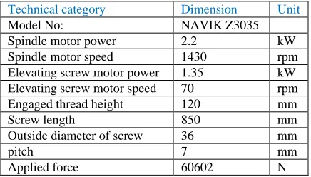
[image:2.612.198.416.146.270.2]When considering the design of elevating screw, materials for screw design is firstly selected. After that, the natural frequency of elevating screw is considered to safe the elevating screw design. Moreover, determination of displacement, velocity and acceleration in transient condition of elevating screw are solved using MATLAB software. Table I shows the parameters considered for design elevating screw for radial drilling machine.
TABLE I
DESIGN PARAMETERS CONSIDERED ELEVATING SCREW FOR RADIAL DRILLING MACHINE
Technical category Dimension Unit
Model No: NAVIK Z3035
Spindle motor power 2.2 kW
Spindle motor speed 1430 rpm
Elevating screw motor power 1.35 kW
Elevating screw motor speed 70 rpm
Engaged thread height 120 mm
Screw length 850 mm
Outside diameter of screw 36 mm
pitch 7 mm
Applied force 60602 N
2.1. Selection of Screw Material
First of all material properties are to be defined. Mild steel, AISI 1035 steel, and alloy steel are chosen for testing material. Among these materials, deformation of AISI 1035 steel is the lowest value than other two materials. So, AISI 1035 steel is suitable material for screw design. The AISI 1035 steel is widely used for manufacturing of screw due to its good machinability and resists heat treatment. The screwismade of AISI 1035 steel with material properties as defined below [6].
TABLE II
PROPERTIES OF MILD STEEL, AISI 1035 STEEL AND ALLOY STEEL
Properties Mild Steel AISI 1035 steel Alloy steel Unit
Density 7800 7860 7700 Kg/m3
Young modulus 200 210 205 GPa
Yield strength 180 282.68 241 MPa
Tensile strength 325 550 448 MPa
III. MODAL ANALYSIS OF ELEVATING SCREW
3.1. The Basics Theory of Modal Analysi
Modal analysis is determined by the characteristics of the material properties and structure of its own, which has nothing to do with the external excitations. Modal analysis is important in vibration point of view. i.e. Vibrations in body are calculated up to what frequency the elevating screw can sustain the load or Harmonic frequency of the body. It also can be a starting point for another, more detailed, dynamic analysis, such as a transient dynamic analysis, a harmonic response analysis, or a spectrum analysis. The natural frequencies and mode shapes are important parameters in the design of a structure for dynamic loading conditions [7].
Static deflection,
AE FL
δ
st = (1)
The working frequency,
st
δ g
2π
1
f = (2)
TABLE III
CALCULATED RESULTS FOR MODAL ANALYSIS ON THE ELEVATING SCREW Parameters Symbol Value Unit
Static deflection δ 0.283 mm
Working frequency f 29.63 Hz
[image:2.612.150.463.379.443.2]3.2. Numerical Result of Modal Analysis on the Elevating Screw
A modal of elevating screw was imported to ANSYS 17 and setting up the boundary conditions for modal analysis. There is only one important boundary fixed support for modal analysis. A modal analysis determines the vibration characteristics (natural frequencies and corresponding mode shapes) of a structure or a machine component. The natural frequencies and mode shapes are used to obtain the transient response by superposition. The numerical results of natural frequencies for global mode shapes are compared with working frequency of elevating screw. The mode shapes obtained must be away from this frequency range so as to make that resonance does not occur.
[image:3.612.71.543.151.299.2][image:3.612.73.541.358.509.2]
Figure 2. First Mode Shape and Second Mode Shape for Elevating Screw
Figure 2 shows the natural frequency of first mode shape and second mode shape at total deformation. From the results, the
natural frequencies of the elevating screw at first and second mode shape are 73 Hz and 77.24 Hz.
[image:3.612.77.539.572.726.2]
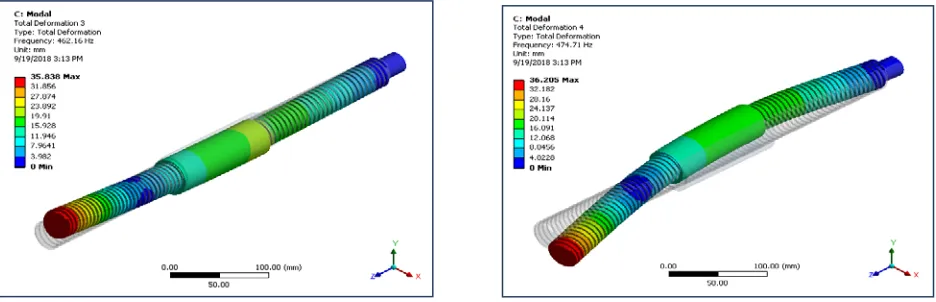
Figure 3. Third Mode Shape and Fourth Mode Shape for Elevating Screw
Figure 3 shows the natural frequency of third mode shape and fourth mode shape at total deformation. From the results, the natural frequencies of the designed elevating screw at third and fourth mode shape are 462.16 Hz and 474.71 Hz.
Figure 4 shows the natural frequency of fifth mode shape and sixth mode shape at total deformation. From the results, the natural frequencies of the designed elevating screw at fifth and sixth mode shape are 1257.50 Hz and 1274.40 Hz.
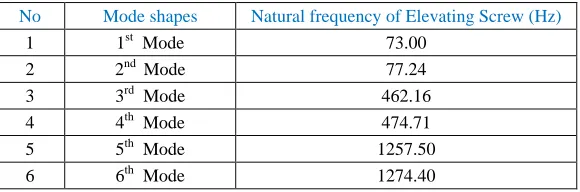
TABLE IV
NUMERICAL RESULTS FOR MODAL ANALYSIS ON THE ELEVATING SCREW
No Mode shapes Natural frequency of Elevating Screw (Hz)
1 1st Mode 73.00
2 2nd Mode 77.24
3 3rd Mode 462.16
4 4th Mode 474.71
5 5th Mode 1257.50
6 6th Mode 1274.40
The present work aims to compare the minimum mode (first mode) frequency from the simulation result of elevating screw. Mode shapes describe the relative position of selected points on a structure for a given vibration mode. Each vibration mode has its unique mode shape, and if the structure is linear the mass normalized mode shapes are supposed to be orthogonal to each other. In first mode shape, the corresponding working frequency of elevating screw is 29.63 Hz and the natural frequency of the elevating screw is 73 Hz. As the working frequency of elevating screw and natural frequency of elevating screw do not match so the elevating screw structural has no tendency of resonance. In all mode shapes, the structure will survive without any deformation.
IV. TRANSIENT ANALYSIS OF ELEVATING SCREW
4.1. Theoretical calculation of transient condition on the elevating screw
All of the forces applied to the structure are known at each instant in time. This is also a time-response method. In transient analysis, both inertia and damping effects are important. There are three cases in this analysis
(i) Over damped case (ζ >1) (ii) Critically damped case (ζ=1) (iii) Under damped case (ζ <1)
Damping ratio range for metal structure has 0.02 to 0.04 [12]. Therefore, the design of elevating screw is under damped case. Mode superposition transient dynamic analysis is a method of using the natural frequencies and mode shapes from modal analysis to characterize the dynamic response of a structure in terms of transient excitations. The equation of motion was expressed as follows:
(t) f kx cx
mx + + =
(3)
Where, x(t), x˙(t), and x¨(t) are, respectively, the displacement, velocity and acceleration in the n discretized points or degrees of freedom (DOF) in the time domain. m, c and k are mass, dampers and springs. f (t) is a vector (with the same size than x) that expresses the force applied on each DOF in the time domain [2].
Mass of elevating screw,
g W
m=
(4)
Spring stiffness,
st δ W
k=
(5)
Natural frequency,
m k
ωn =
(6)
Damped natural frequency, 2
ζ 1 ω
ωd = n −
(7)
Period of elevating screw,
n ω
2π
τ=
(8)
Logarithmic decrement,
2 ζ -1
2π
Displacement of elevating screw,
− − − −= e ξω tcos(ω t φ)
2 ξ 1 1 1 k F
x(t) 0 n d
(10)
Velocity of elevating screw,
− − − + − − −= e ξω tsin(ω t φ)
2 ξ 1 ω φ) t cos(ω t ξω e 2 ξ 1 ξω k F (t)
x 0 n n d d n d
(11)
Acceleration of elevating screw,
)] t cos(ω 2 ζ 1 t ξω e d 2 ω φ) t sin(ω t ξω e 2 ξ 1 ω 2ξξ φ) t cos(ω t ζω e 2 ζ 1 2 ω 2 ζ [ k F (t) x d n d n d n d n n
0 −ϕ
− − + − − − − − − − − =
(12) MATLAB program
*************************Theoretical Calculation of Transient Condition on the Elevating Screw************************* clc
F=60602; % Applied force on the elevating screw n=70; % speed of elevating screw
E=210; % young modulus
g=9.81; % acceleration due to gravity L=850; % length of screw
dm=32.5; % mean diameter of screw zeta=.03 % damping ratio
deta=(u*L*10^-3*4)/(pi*(dm*10^-3)^2*E*10^9) m=u/g k=u/deta wn=sqrt(k/m) zwn=zeta*wn; wd=wn*sqrt(1-zeta^2) q=sqrt(1-zeta^2); wd=wn*sqrt(1-zeta^2); phi=atan(zeta/q) r=zeta^2*wn^2 s=wd^2 v=zeta*wn*wd t = 0:0.001:4;
x=(F/k).*(1-(1/q).*exp(-zwn.*t).*cos(wd.*t-phi)) plot(t,x)
xlabel('time,(s)')
ylabel('displacement, (m)')
title('Response for under damped system’) pause
t=0:0.001:3.999;
c=(F/k).*[(zwn/q).*exp(-zwn.*t).*cos(wd.*t-phi)+wd.*exp(-zwn.*t).*(1/q).*sin(wd.*t-phi)] plot(t,c)
xlabel('time, (s)') ylabel('velocity, (m/s)')
title('Response for under damped system’) pause
t=0:0.001:3.998;
a=(F/k).*[-(r/q).*exp(-zwn.*t).*cos(wd.*t-phi)-2*v.*exp(-zwn.*t)*(1/q).*sin(wd.*t-phi)+(s/q).*exp(-zwn.*t).*cos(wd.*t-phi)] plot(t,a)
xlabel('time, (s)')
ylabel('acceleration, (m/s^2)')
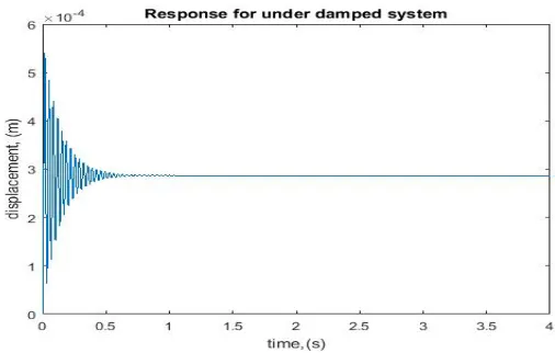
Figure 5.Displacement Versus Time Variation on the Elevating Screw Using MATLAB
[image:6.612.169.439.321.474.2]Figure 5 shows displacement with time variation on the elevating screw using MATLAB software. The characteristic of displacement presents some oscillations around its balance position which is equal to 2.99×10⁻⁴ m corresponding to the elementary step displacement of the elevating screw. The distribution of displacement on the elevating screw changes from 0 to 0.7 s. The maximum displacement occurs between 0 s to 0.25 s. The maximum displacement 5.2×10⁻⁴ m is found during 0 s to 0.25 s. The value of displacement is steadily decreased from 0.26 s to 0.7 s. Displacement is convergence after 0.7 s due to damping effect.
Figure 6.Velocity Versus Time Variation on the Elevating Screw Using MATLAB
[image:6.612.171.432.562.720.2]Figure 6 describes velocity with time variation in transient calculation using MATLAB software. The elevating screw starts from zero velocity to reach maximum value of 0.045 m/s then it tends to zero value at 4 s where the elevating screw reaching at the rest position. The velocity distribution on the elevating screw changes from 0 to 0.7 s. The maximum velocity occurs between 0 s to 0.25 s. The velocity distribution is gradually decreased from 0.26 s to 0.7 s. The value of velocity is convergence after 0.7 s due to damping effect.
Figure 7 illustrates acceleration with time variation in transient calculation using MATLAB software. The elevating screw starts from zero acceleration to reach maximum value of 8 m/s2 then it tends to zero value at 4s where the elevating screw reaching at the rest position. The acceleration on the elevating screw changes from 0 to 0.7 s. The maximum displacement occurs between 0 s to 0.25 s. The acceleration of elevating screw is steadily decreased from 0.26 s to 0.7 s. Acceleration of elevating screw is convergence after 0.7 s due to damping effect.
2.3.1. Numerical Results of Transient Structural Analysis on the Elevating Screw
[image:7.612.198.416.233.408.2] [image:7.612.85.536.462.647.2]The transient structural analysis is also called time-history analysis that specifically uses the ANSYS Mechanical solver. This type of analysis is used to determine the dynamic response of a structure under the action of any general time-dependent loads [2]. This type of analysis can also be used to determine the time-varying displacements, velocity and acceleration in a structure as it responds to any transient loads. The time scale of the loading is such that the inertia or damping effects are considered to be important. Table V shows input data used in simulation process.
TABLE V
INPUT DATA USED IN SIMULATION PROCESS
No Category Input Data
1 Analysis type Transient structural
2 Geometry 3D
3 Material Selection AISI 1035 steel
4 Mesh
Number of elements 132880
5 Boundary condition Applied load
Fixed-Free Total Time Frequency Damping ratio
60602 N Upper end of screw
4 s 29.63 Hz
0.03 6
Output
Displacement Velocity Acceleration
The model of elevating screw is drawn in SOLIDWORKS software and is added to the geometry in ANSYS 17 software. This geometry model is meshed with high smoothing. Meshing is the process in which the mechanism geometry is spatially discretized into elements and nodes. The mesh model is imported to transient structural analysis.
.
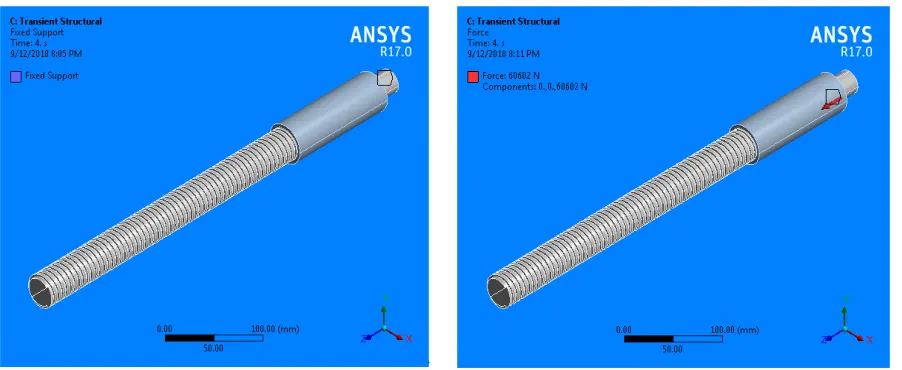
Figure.8. Fixed Support of the Elevating Screw Figure.9. Force 60.6 kN Applied on the Elevating Screw
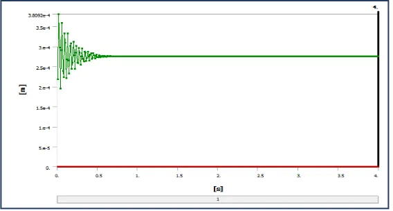
Figure 10. Displacement Versus Time Variation in Transient Analysis using ANSYS software
[image:8.612.188.461.317.480.2]Figure 10 shows displacement with time variation in transient analysis using ANSYS software. The characteristic of displacement presents some oscillations around its balance position which is equal to 2.8 ×10⁻⁴ m corresponding to the elementary step displacement of the elevating screw. The displacement excitation was expected to generate the correct response spectra because ANSYS requires a displacement time history to generate it. The distribution of displacement on the elevating screw changes from 0 to 0.7 s. The maximum displacement is found between 0 s to 0.25 s. The maximum displacement 3.9 ×10⁻⁴ m is found from 0 s to 0.25 s. The value of displacement is gradually decreased from 0.26 s to 0.6 s. Displacement is convergence after 0.6 s due to damping effect.
Figure 11.Velocity Versus Time Variation in Transient Analysis using ANSYS software
Figure 11 describes velocity with time variation in transient analysis using ANSYS software. The moving part starts from the zero velocity to reach a maximum of 0.035 m/s then it tends to the zero value at total time 4 s where the elevating screw reaching the rest position. The velocity distribution on the elevating screw changes from 0 to 0.6 s. The maximum velocity occurs between 0 s to 0.25 s. The velocity distribution is gradually decreased from 0.26 s to 0.6 s. The value of velocity is convergence after 0.6 s due to damping effect.
[image:8.612.189.465.566.718.2]Figure 12 shows acceleration with time variation in transient analysis using ANSYS software. The acceleration of elevating screw starts from the 0 m/s2 to reach a maximum of 6.58 m/s2 then it tends to the zero value at total time 4 s where the elevating screw reaching the rest position. The acceleration distribution on the elevating screw occurs from 0 to 0.6 s. The maximum acceleration distribution is found between 0 s to 0.25 s. The maximum value of acceleration is 5.8 m/s2 during 0 s to 0.25 s. The acceleration of elevating screw is gradually declined from 0.26 s to 0.6 s. The value of velocity is convergence after 0.6 s due to damping effect.
CONCLUSIONS
Elevating screw is an essential part of the radial drilling machine. Every structure has its own natural frequency and logarithmic decrement or damping for each vibration mode. Generally, natural frequency is an important parameter in the structure and is related to the rigidity and density of the vibrating object. The modal analysis of elevating screw has been done to get the first 6 order frequencies and vibration modes. The natural frequency of first mode shape is less than other mode shape. The first mode shape of natural frequency on the elevating screw is 73 Hz, the maximum deformation occurs at the free position of the elevating screw. The working frequency of elevating screw is 29.63 Hz. If the first mode shape natural frequency is greater than the working frequency of elevating screw, the structure is safe. The dynamic behaviour of elevating screw system with a moving nut was calculated using step response function for a time step of duration 4 s. A computer program was written in MATLAB to generate displacement, velocity and acceleration time histories of the elevating screw. Theoretical calculation of maximum displacement 5.2 ×10⁻⁴ m, velocity 0.045 m/s and acceleration 8 m/s2 are occurred during 0 s to 0.25 s using MATLAB software. Numerical results of elevating screw are found maximum displacement 3.75 ×10⁻⁴ m, velocity 0.035 m/s and acceleration 6.59 m/s2 during 0 s to 0.25s using ANSYS software. Based on these results, the vibration response of elevating screw decrease with time increase and tends to the static response due to the dissipation of system energy.
ACKNOWLEDGMENT
First of all, the author is grateful to Dr. Sint Soe, Rector, Mandalay Technology University, for his kindness and valuable permission to summit the paper for the Ph.D Degree. A special thanks is offered to Dr. Htay Htay Win, Professor and Head of Department of Mechanical Engineering, Mandalay Technological University, for her encouragement, constructive guidance and kindly advice throughout the preparation of this paper.
REFERENCES
[1] Henri P. Gavin, Vibrations of Single Degree of Freedom Systems, Structural Dynamics, Duke University,Fall, 2016. [2] Audel, Machine Shop Tools and Operations, fifth edition, 2004.
[3] Jesudoss, G. J.: General Machinist Theory, 2011.
[4] Tong Hui, Nonlinear Cyclic Transient Dynamic Analysis for Bladed Disk Tip Deflection, April 10-15, 2016. [5] William J. Palm III, University of Rhode Island, System Dynamics,Second Edition, 2010.
[6] D. Gandy, Carbon Steel Handbook, second edition, 2007.
[7] Pin Hong,Dynamic Characteristics Analysis of Ball Screw Based on Workbench, Vol. 5, No. 3; ISSN 2162-139X, June 2015. [8] William J. Palm III, University of Rhode Island, System Dynamics,Second Edition, 2010.
[9] Robert M. Ebeling,Chapter Six,Transient and Steady State Responses, 2015.
[10]
Howard A. Gaberson,Pseudo Velocity Shock Spectrum Rules for Analysis of Mechanical Shock, 2016. [11] Dr Mustafa M Aziz,system response,Control Engineering, 2015.
[12] D.F. LEDEZMA, Transient Vibration of the single degree of freedom systems, 2015.
AUTHORS
First Author – Aye Myint Kyi, Ph.D Student, Mandalay Technological University, [email protected]
Second Author – Ei Ei Htwe, Professor, Mandalay Technological University, [email protected]