www.ijsrp.org
Design and Implementation of an Eight Bit Multiplier
Using Twin Precision Technique and Baugh-Wooley
Algorithm
Ramesh Kumar Mallavarapu*, Tota Srinivasa Rao**
*ECE Department, Sri Vasavi Engineering College.
**ECE Department, Sri Vasavi Engineering College.
Abstract—A novel technique for integer multiplication is implemented in this project. It is twin precision technique which is noteworthy for its low power dissipation. Multiplier is adapted to bitwidth of the operands to be computed to obtain the reduced power dissipation. The technique also results in an increased computational throughput, by allowing several narrow-width operations to be computed in parallel. Using Twin-precision technique with Baugh-Wooley algorithm, we achieve significant delay penalty and good power reduction.
Index Terms-twin precision, throughput, narrow-width operations.
I. INTRODUCTION
ultiplication is a complex arithmetic operation, which is reflected in its relatively high signal propagation delay, high power dissipation, and large area requirement. When choosing a multiplier for a digital system, the bit width of the multiplier is required to be at least as wide as the largest operand of the applications that are to be executed on that digital system. The bit width of the multiplier is, therefore, often much larger than the data represented inside the operands, which leads to unnecessarily high power dissipation and unnecessary long delay.
This resource waste could partially be remedied by having several multipliers, each with a specific bit width, and use the particular multiplier with the smallest bit width that is large enough to accommodate the current multiplication. Such a scheme would assure that a multiplication would be computed on a multiplier that has been optimized in terms of power and delay for that specific bit width. However, using several multipliers with different bit widths would not be an efficient solution, mainly because of the huge area overhead. It has been shown in many studies that more than 50% of the instructions are instructions where both operands are less than or equal to 16 bits. Such operations are called narrow-width operations. This property has been explored to save power, through operand guarding. In operand guarding the most significant bits of the operands are not switched, thus power is saved in the arithmetic unit when multiple narrow-width operations are
computed consecutively. It is shown that the power reduction of an operand-guarded integer unit was 54% to 58%, which accounts for a total power reduction of 5–6% for an entire data path. Narrow-width operands have also been used to increase instruction throughput, by computing several narrow-width operations in parallel on a full-width data path. It is showed a 7% speedup for a simple 4-bit ALU, which excluded the multiplier, in parallel with four simple 16-bit ALUs that share a 64-bit routing.
[image:1.612.320.556.488.594.2]There have been several studies on operand guarding for multipliers. Two-dimensional operand guarding was introduced for array multipliers, resulting in a power dissipation that was only 33% of a conventional array multiplier. A similar investigation on a 32-bitWallace multiplier results in reduction of the switching activity by 72% with the use of 16-bit operand guarding. While there has been a lot of work on simple schemes for operand guarding, work that simultaneously considers multiplication throughput is scarcer.
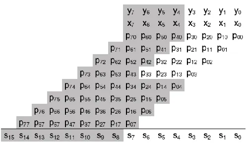
Figure 1: Illustration of an unsigned 8-bit multiplication Achieving double throughput for a multiplier is not as straightforward as, for example, in an adder, where the carry chain can be cut at the appropriate place to achieve narrow-width additions. It is of course possible to use several multipliers, where at least two have narrow bit width, and let them share the same routing, but such a scheme has several drawbacks: The total area of the multipliers would increase, since several multiplier units are used. The use of several multipliers increases the fan out of the signals that drive the inputs of the multipliers.
www.ijsrp.org
Higher fan out means longer delays and/or higher power dissipation.
There would be a need for multiplexers that connect the active multiplier(s) to the result route. These multiplexers would be in the critical path, increasing total delay as well as power dissipation. Work has been done to use 4:2-reduction stages to combine small tree multipliers into larger multipliers. This can be done in several stages, creating a larger multiplier out of smaller for each extra 4:2 reduction stage. The desired bit width of the multiplication is then obtained by using multiplexers, which has a negative effect on the delay.
We present the twin-precision technique that offers the same power reduction as operand guarding and the possibility of performing double-throughput multiplications. The twin-precision technique is an efficient way of achieving double throughput in a multiplier with low area overhead and with only a small delay penalty. We show how to apply the twin-precision technique on a un signed multipliers based on the regular High Performance Multiplier reduction tree. Baugh–Wooley algorithm is used for the multiplication.
II. PROPOSEDTECHNIQUE
A. Twin-Precision Using the Baugh–Wooley Algorithm
TWIN-PRECISION FUNDAMENTALS:
We present the twin-precision technique using an illustration of unsigned binary multiplication. In an unsigned binary multiplication each bit of one of the operands, called the multiplier, is multiplied with the second operand, called multiplicand.
[image:2.612.323.572.79.224.2]That way one row of partial products is generated. Each row of partial products is shifted according to the position of the bit of the multiplier, forming what is commonly called the partial- product array. Finally, partial products that are in the same column are summed together, forming the final result. An illustration of an 8-bit multiplication is shown in Fig. 1. Let us look at what happens when the precision of the operands is smaller than the multiplier we intend to use. In this case, the most significant bits of the operands will only contain zeros, thus large parts of the partial-product array will consist of zeros. Further, the summation of the most significant part of the partial-product array and the most significant bits of the final result will only consist of zeros. An illustration of an 8-bit multiplication, where the precision of the operands is four bits, is shown in Figure 2.
Figure 2: Illustration of an unsigned 8-bit multiplication where the precision of the operands is smaller than the precision of the multiplication. Unused bits of operands and product, as well as unused partial products, are shown in gray.
Figure 2 shows that large parts of the partial products are only containing zeros and are, thus, not contributing with any useful information for the final result. What if these partial products could be utilized for a second, concurrent multiplication? Since partial products of the same column are summed together, it would not be wise to use any of the partial products that are in the same column as the multiplication that is already computed. Looking closer at the 4-bit multiplication marked in white in Fig. 2, one can also observe that the column at position S7 should not be used either. This is because that column might have a carry from the active part of the partial-product array that will constitute the final S7. Altogether this makes only the partial products in the most significant part of the partial-product array available for a second multiplication. In order to be able to use the partial products in the most significant part, there has to be a way of setting their values. For this we can use the most significant bits of the operands, since these are not carrying any useful information. By setting the other partial products to zero, it is then possible to perform two multiplications within the same partial-product array, without changing the way the summation of the partial-product array is done. How the partial products, shown in gray, can be set to zero will be investigated in the implementation section later on. Assume, for now, that there is a way of setting unwanted partial products to zero, then it suddenly becomes possible to partition the multiplier into two smaller multipliers that can compute multiplications in parallel. In the above illustrations the two smaller multiplications have been chosen such that they are of equal size.
www.ijsrp.org
NLSP , shown in white, and the multiplication in the Most Significant part (MSP) with size MSP , shown in black.
NFULL = NLSP + NMSP
It is functionally possible to partition the multiplier into even more multiplications. For example, it would be possible to partition a 64-bit multiplier into four 16-bit multiplications. Given a number K of low precision multiplications their total size need to be smaller or equal to the full
precisionmultiplication.
For the rest of this investigation, the precision of the two smaller multiplications will be equal and half the precision (N=2) of the full precision (N) of the multiplier.
[image:3.612.312.555.87.618.2]BAUGH WOOLEY ALGORITHMS:
Fig. 3 illustrates the flow chart for the algorithm of an 8-bit case, where the partial-product array has been reorganized according to the scheme of Hatamian. The creation of the reorganized partial-product array comprises three steps:
The most significant partial product of the first Nth rows and the last row of partial products except the most significant have to be negated,
A constant one is added to the nth column,
The most significant bit (MSB) of the final result is negated.
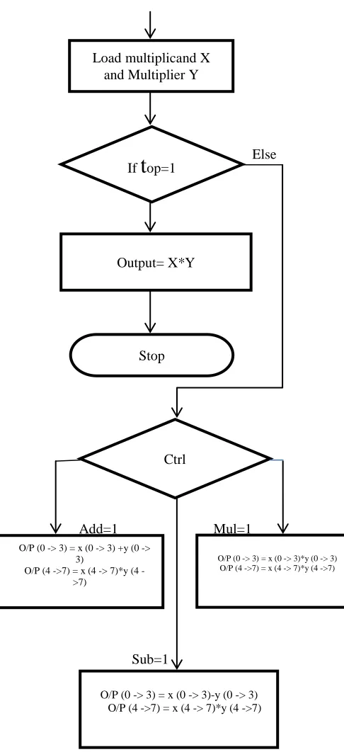
Figure 3: Flowchart for Baugh-Wooley algorithm
TWIN PRECISION USING THE BAUGH WOOLEY ALGORITHM:
Else
Add=1 Mul=1
[image:3.612.60.231.439.593.2]Sub=1
Figure 4: Flowchart for Twin precision Baugh-Wooley algorithm.
III. IMPLEMENTATION
It is not as easy to deploy the twin-precision technique onto a Baugh Wooley multiplication as it is for the unsigned Start
Load multiplicand X and Multiplier Y
If
t
op=1Output= X*Y
Stop
Ctrl
O/P (0 -> 3) = x (0 -> 3) +y (0 -> 3)
O/P (4 >7) = x (4 > 7)*y (4 ->7)
O/P (0 -> 3) = x (0 -> 3)*y (0 -> 3) O/P (4 ->7) = x (4 -> 7)*y (4 ->7)
www.ijsrp.org
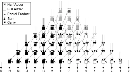
multiplication, where only parts of the partial products need to be set to zero. To be able to compute two signed N/2 multiplications, it is necessary to make a more sophisticated modification of the partial-product array. Figure 5 illustrates an 8 bitBaugh-Wooley multiplication, in which two 4-bit multiplications have been depicted in white and black.
When comparing the illustration of Figure 5 with that of Figure 7, one can see that the only modification needed to compute the 4-bit multiplication in the MSP of the array is an extra sign bit „1‟ in column S12 . For the 4-bit multiplication in the LSP of the array, there is a need for some more modifications. In the active partial-product array of the 4-bit LSP multiplication(Shown in white), the most significant partial product of all rows, except the last, needs to be negated.
[image:4.612.319.562.72.200.2]For the last row it is the opposite, here all partial products, except the most significant, are negated. Also for this multiplication a sign bit „1‟ is needed, but this time in column S4. Finally the MSB of the results needs to be negated to get the correct result of the two 4-bit multiplications. To allow for the full-precision multiplication of size to N coexist with two multiplications of N/2 size in the same multiplier, it is necessary to modify the partial-product generation and the reduction tree. For the N/2 -bit multiplication in the MSP of the array all that is needed is to add a control signal that can be set to high, when the N/2-bit multiplication is to be computed and to low, when the full precision N multiplication is to be computed. To compute the N/2-bit multiplication in the LSP of the array, certain partial products need to be negated. This can easily be accomplished by changing the two-input AND gate that generates the partial product to a two-input NAND gate followed by an XOR gate.
Figure 5: Illustration of a signed 8-bit multiplication, using the Baugh–Wooley algorithm, where one 4-bit multiplication, shown in white, is computed in parallel with a second 4-bit multiplication, shown in black.
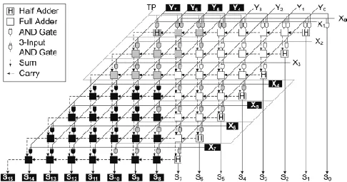
Figure 6: Block diagram of an unsigned 8-bit twin precision multiplier.
When computing the N/2 -bit LSP multiplication, the control input to the XOR gate is set to low making it work as a buffer. When computing a full-precision N multiplication the same signal is set to high making the XOR work as an inverter. Finally the MSB of the result needs to be negated and this can again be achieved by using an XOR gate together with an inverted version of the control signal for the XOR gates used in the partial-product generation. Setting unwanted partial products to zero can be done by three-input AND gates as for the unsigned case.
Figure 6 shows an implementation of a twin-precision 8-bit Baugh-Wooley multiplier and it consist of three things:
The half adders in column 4 and 8 have been changed to full adders in order to fit the extra sign bits that are needed
For the sign bit of the 4-bit MSP multiplication there is no half adder that can be changed in column 12, so here an extra half adder has been added, which makes it necessary to also add half adders for the following columns of higher precision.
[image:4.612.37.294.507.647.2]www.ijsrp.org
Figure 7: Block diagram of a signed 8-bit multiplication, using the Baugh–Wooley algorithm, where one 4-bit multiplication,
shown in white, is computed in parallel with a second 4-bit multiplication, shown in black.
IV. SIMULATIONRESULTS
[image:5.612.42.294.344.479.2]TWIN BAUGH WOOLEY RESULT:
Figure 8: Simulation results for Twin precision Baugh Wooley algorithm.
SYNTHESIS RESULTS:
Following results are achieved in the synthesis of our process and showed the significant reduction in the power dissipation in the proposed multiplier.
Techniques Execution Time Power Consumption Existing 7.675ns 16mW Proposed 6.788ns 11mW
V. CONCLUSION
The twin precision multiplier presented in this paper offers a good tradeoff between precision flexibility, area, delay and power dissipation by using same multiplier for doing N, N/2
or two N/2-b multiplications. In comparison to a conventional 16-b twin precision multiplier has 8% higher transistor count and 9% longer delay. The relative transistor count overhead decreases for larger multipliers, since the number of AND gates needed to set the partial products to zero does not grow as fast as the number of adders in the tree.
We have shown that power cut-off techniques can be deployed in different regions of a twin precision functional unit, so that static leakage reduction can be effected not only when the entire unit is idle, but also when only parts of the unitary active, i.e. when the unit operates in half precision mode
R
EFERENCES1. Abddollahi, M. Pedrem, F. Fallah and I. Ghosh pre-computation-based guarding for dynamic and leakage power reduction. In proceedings of the 21st international conferences on computer design, pages 901, 2003.
2. J. Hughes, K. Jeppson, P. Larsson-Edefors, M. Sheeran, Stenstr¨om, and L. J. Svensson. FlexSoC: Combining Flexibility and Efficiency in SoC Designs. In Proceedings of the IEEE NorChip Conference, 2003 3. ] S. Mathew, M. Anders, B. Bloechel, T. Nguyen, R.
Krishna- murthy, and S. Borkar. A 4GHz 300mW 64b Integer Execution ALU with Dual Supply Voltages in 90nm CMOS. In Pro- ceedings of the International Solid State Circuits Conference, pages 162s, 2004. 4. Z. Huang and M. D. Ercegovac. Two-Dimensional
Signal Gating for Low-Power Array Multiplier Design. In Proceedings of the IEEE International Symposium on Circuits and Systems pages II–IJ vol.1, 2002. 5. K. Callaway and E. E. Swartzlander, Jr. Optimizing
Multi- pliers for WSI. In Proceedings of the Fifth Annual IEEE International Conference on Wafer Scale Integration, pages 85Ì1993.
6. ] P. Mokrian, M. Ahmadi, G. Jullien, and W. Miller. A Recon- figurable Digital Multiplier Architecture. In Proceedings of the IEEE Canadian Conference on Electrical and Computer Engineering, pages 125X, 2003.
7. ] H. Eriksson. Efficient Implementation and Analysis of CMOS Arithmetic Circuits. PhD thesis, Chalmers University of Technology, 2003.
8. ] C. R. Baugh and B. A. Wooley. A Two‟s Complement Par allel Array Multiplication Algorithm. IEEE Transactions on Computers, 22:1045‟, December 1973.–701, Jul. 2000.
9. V. G. Oklobdzija, D. Villeger, and S. S. Liu A Method for Speed Optimized Partial Product Reduction and Generation of Fast Parallel Multipliers Using an Algorithmic approach IEEE Transactions on Computers, 45C):294˜6 march 1996.
FPGA-www.ijsrp.org
Based Wave Pipelined DSP Blocks” IEEE Trans. Very Large Scale Integr. (VLSI) Syst., vol.13. No 7. pp 783-792, July 2005.
11. L.Benini, G.D.Micheli, A.Macii, E.Macii, M. Poncino, and R.Scarsi, “Glitching power minimization by selective gate freezes,” IEEE Trans. Very Large Scale Integr. (VLSI) Syst., vol. 8, no. 3, pp.287²97, June 2000.
12. C. S. Wallace, “A suggestion for a fast multiplier,” IEEE Trans. Electron.Comput., vol. 13, pp. 14–17, Feb. 1964