dp"*-*.
" \
60480000
<g g) CONTRpL DATA
NETWORK PRODUCTS
NETWORK ACCESS METHOD
VERSION 1
NETWORK DEFINITION LANGUAGE
REFERENCE MANUAL
REVISION RECORD
^ 3 ^ £ yRevision
A (12/01/76)
B (04/01/77)
C (04/28/78)
0 (08/15/78)
E (12/18/78)
F (08/10/79)
G (05/23/80)
H (10/31/80)
J (05/29/81)
K (12/22/82)
L (09/30/83)
M (09/19/84)
N (09/30/85)
P (12/16/85)
R (07/31/86)
S (04/23/87)
T (12/08/88)
D e s c r i p t i o n
Original release. Programming System Report (PSR) level 439.
Revised at PSR level 446 for technical corrections.
Completely revised for NAM Version 1.1 release at PSR level 472 to include support of remote and foreign NPUs, asynchronous and HASP TIPs, virtual terminals, IAF, and TVF.
Revised at PSR level 477 for technical corrections.
Revised at PSR level 485 to include autorecognition up to 1200 baud and for technical c o r r e c t i o n s .
Revised to reflect release of NAM Version 1.2. Included are descriptions of special editing support, extended APL support, and various technical corrections.
Revised at PSR level 517 to reflect support of the 714-30 terminal class, and of 714-10/20 and 714-30 line printers. Various technical corrections are also included.
Revised at PSR level 528 to document support of the X.25 protocol.
Revised to reflect release of NAM Version 1.3 at PSR level 541 to document support of the PRU interface and the BSC protocol (2780/3780 terminal support). Also includes various t e c h n i c a l c o r r e c t i o n s .
Revised to reflect release of NAM Version 1.5 (Version 1.4 does not exist) at PSR level 580, which supports the Network Access Method and Communication Control Program Version 3.5 under NOS Version 2; this manual no longer applies to NOS Version 1 systems. This is a complete reprint.
Revised to reflect release of NAM Version 1.6 at PSR level 599, which supports the Network Access Method and Communications Control Program Version 3.6 under NOS Version 2 . T h i s i s a c o m p l e t e r e p r i n t .
Revised to reflect release of NAM Version 1.7 at PSR level 617, which supports the Network Access Method and Communications Control Program Version 3.7 under NOS Version 2.3. Support of the CYBER 170 800 Series models and the CYBER 180 Computer Systems is documented.
Revised to reflect release of NAM Version 1.8 at PSR level 642, which supports the Network Access Method and Communications Control Program Version 3.8 under NOS Version 2.4.2. Miscellaneous technical changes are included. This is a complete reprint.
Revised to reflect release of NAM Version 1.8 at PSR level 647, which supports the Network Access Method and Communications Control Program Version 3.8 under NOS 2.4.3 and the release of CDCNET Version 1.0. Miscellaneous technical changes are included.
Revised to reflect release of NAM Version 1.8 at PSR level 664, which supports the Network Access Method and Communications Control Program Version 3.8 under NOS 2.5.1 and the release of CDCNET 1.1. Miscellaneous technical changes are included.
Revised to reflect release of NAM Version 1.8 at PSR level 678, which supports the Network Access Method and Communications Control Program Version 3.8 under NOS 2.5.2 and
the release of CDCNET 1.2. Three new parameters have been added to the OUTCALL statement and changes have been made to default values for other parameters to simplify connections
to NOS/VE. Miscellaneous technical changes are included.
Revised to reflect release of NAM Version 1.8 at PSR level 716, which supports the Network Access Method and Communications Control Program Version 3.8 under NOS 2.7.1 and
the release of CDCNET 1.4. Miscellaneous technical changes are included.
•»s»"S\
REVISION LETTERS I, 0, Q, AND X ARE NOT USED
©COPYRIGHT CONTROL DATA CORPORATION 1976, 1977, 1978, 1979, 1980, 1981, 1982, 1983, 1984, 1985, 1986, 1987, 1988 All Rights Reserved
Printed in the United States of America
i i
Address comments concerning this manual to:
CONTROL DATA CORPORATION Te c h n i c a l P u b l i c a t i o n s P.O. Box 3492
SUNNYVALE, CALIFORNIA 94088-3492
or use Comment Sheet in the back of this manual
LIST OF EFFECTIVE PAGES
New features, as well as changes, deletions, and additions to information in this manual are indicated by bars in the margins or by a dot near the page number if the entire page is affected. A bar by the page number
indicates pagination rather than content has changed.
Page
Front Cover Title Page
i i i i i / i v v / v i
v i i v i i i
i x x
x i / x i i x i i i
1-1 1-2 1-3 1-4 1-5 1-6 1-7 1-8 1-9 1-10
1-11 thru 1-18 2-1 2-2 2-3 2-4 2-5 2-6 2-7 2-8 3-1
3-2 thru 3-9 4-1
4-2
4-3 thru 4-5 4-6
4-7 4-8 4-9 4-10
4-11 thru 4-17
R e v i s i o n Page
4-18
4-19 thru 4-23 4-24
4-25 thru 4-27 5-1
5-2 thru 5-6 5-7
5-8 thru 5-20 5-21
5-22 5-23 6-1
6-2 thru 6-5 6-6
6-7 thru 6-17 6-18
6-19
6-20 thru 6-40 6-41
6-42 thru 6-49 7-1 7-2 7-3 7-4 7-5 7-6 7-7 7-8 7-9 7-10 7-11 7-12 7-13
7-14 thru 7-22 7-23
7-24 7-25
7-26 thru 7-28 8-1 8-2 8-3 Revision T N R N M N P N P N N M N P N M S N P N N S N K N N S N P N N M M N M N R N P L T Page Revision
8-4 thru 8-5 8-6 thru 8-12 9-1 9-2 10-1 10-2 10-3 10-4
11-1 thru 11-28 A-l thru A-3 A-4
A-5 A~6
A-7 thru A-19 A-20 thru A-23 A-24 thru A-32 A-33 thru A-48 B-l
B-2 B-3
B-4 thru B-8 B-9
B-10 B - l l
C-l thru C-3 C-4 C-5 C-6 D-l D-2 D-3 E-l
E-2 thru E-6 F - l
Index-1 thru -15 Comment Sheet/Mailer Back Cover
PREFACE
^
\
T h i s m a n u a l d e s c r i b e s t h e N e t w o r k D e fi n i t i o n Language (NDL) for the CONTROL DATA® Network Access Method (NAM), Version 1.8. It'assumes that t h e r e a d e r i s a n e t w o r k s i t e a d m i n i s t r a t o r f a m i l i a r with the Network Operating System (NOS) and other software in the networks product set.
T h e N e t w o r k A c c e s s M e t h o d Ve r s i o n 1 . 8 o p e r a t e s under control of the NOS 2 operating system for the CDC® CYBER 180 Series; CYBER 170 Series; CDC CYBER 7 0 M o d e l s 7 1 , 7 2 , 7 3 , a n d 7 4 ; a n d 6 0 0 0 S e r i e s Computer Systems.
T h e N e t w o r k D e fi n i t i o n L a n g u a g e p r o c e s s o r i s a compiler used by a network administrator to create and maintain the files that define the physical and l o g i c a l s t r u c t u r e o f t h e n e t w o r k f o r o t h e r n e t w o r k
s o f t w a r e , w h i c h i n t u r n e s t a b l i s h e s , i n i t i a l i z e s , and operates the network.
RELATED PUBLICATIONS
R e l a t e d m a t e r i a l i s c o n t a i n e d i n t h e C o n t r o l D a t a C o r p o r a t i o n p u b l i c a t i o n s l i s t e d b e l o w . T h e p u b l i c a t i o n s a r e l i s t e d w i t h i n g r o u p i n g s t h a t i n d i c a t e
relative importance to readers of this manual.
T h e N O S S y s t e m I n f o r m a t i o n M a n u a l i s a n o n l i n e m a n u a l t h a t i n c l u d e s b r i e f d e s c r i p t i o n s o f a l l N O S and N O S pr od uc t m anual s. To ac c es s t hi s manual , log in to NOS and enter the command EXPLAIN.
The following publications are of primary interest:
P u b l i c a t i o n
P u b l i c a t i o n Number
C D C N E T C o n c e p t u a l O v e r v i e w 6 0 4 6 1 5 4 0
C D C N E T C o n fi g u r a t i o n a n d S i t e A d m i n i s t r a t i o n M a n u a l 6 0 4 6 1 5 5 0
CDCNET Systems Programmer's Reference Manual
V o l u m e 1 , B a s e S y s t e m S o f t w a r e 6 0 4 6 2 4 1 0
CDCNET Systems Programmer's Reference Manual Volume 2, Network Management Entities and
L a y e r I n t e r f a c e s 6 0 4 6 2 4 2 0
CDCNET Systems Programmer's Reference Manual
V o l u m e 3 , N e t w o r k P r o d u c t s 6 0 4 6 2 4 3 0
CDCNET Systems Programmer's Reference Manual
V o l u m e 4 , T e r m i n a l I n t e r f a c e P r o g r a m s 6 0 4 6 2 4 4 0
C D C N E T T e r m i n a l I n t e r f a c e U s a g e M a n u a l 6 0 4 6 1 5 3 0
CYBER Cross System Version 1 Build Utilities
R e f e r e n c e M a n u a l 6 0 4 7 1 2 0 0
Network Products Network Access Method Version 1
H o s t A p p l i c a t i o n P r o g r a m m i n g R e f e r e n c e M a n u a l 6 0 4 9 9 5 0 0
Network Access Method Version 1/
Communications Control Program Version 3
T e r m i n a l I n t e r f a c e s R e f e r e n c e M a n u a l 6 0 4 8 0 6 0 0
NOS Version 2 Reference Set, Volume 3, System Commands 60459680
N O S V e r s i o n 2 A n a l y s i s H a n d b o o k 6 0 4 5 9 3 0 0
/ ^ * ^
The following publication is of secondary interest:
P u b l i c a t i o n P u b l i c a t i o n N u m b e r
N O S V e r s i o n 2 I n s t a l l a t i o n H a n d b o o k 6 0 4 5 9 3 2 0
Sites within the. United States can order CDC manuals from Control D a t a C o r p o r a t i o n , L i t e r a t u r e a n d D i s t r i b u t i o n S e r v i c e s , 3 0 8 N o r t h Dale Street, St. Paul, Minnesota 55103.
Other sites can order CDC manuals by contacting the local sales o f fi c e .
T h i s p r o d u c t i s i n t e n d e d f o r u s e o n l y a s d e s c r i b e d i n th i s d o c u m e n t. C o n tr o l D a ta c a n n o t b e r e s p o n s i b l e f o r t h e p r o p e r f u n c t i o n i n g of undescribed features or parameters.
A l s o , i f y o u h a v e a c c e s s t o S O LV E R , t h e C D C o n l i n e f a c i l i t y f o r
r e p o r t i n g p r o b l e m s , y o u c a n u s e i t t o s u b m i t c o m m e n t s a b o u t t h i s , « s 3 S \ m a n u a l . W h e n i t p r o m p t s y o u f o r a p r o d u c t i d e n t i fi e r f o r y o u r T | report, please specify NA5.
CONTENTS
J$?*N
NOTATIONS
I. INTRODUCTION
Network Definition Language Processor Basic Network Concepts
Supervisory Programs
Network Access Method Interfaces Simple Network
Administrative Operators Variants of NPU Software Packet-Switching Network Multiple-Host Network Defining a CDC Network
Hardware Elements Host Processors
Network Processing Units Couplers
Trunks
Communication Lines Terminals
Devices Software Elements
Data Structures and Flow Host-Resident Software NPU-Resident Software CDCNET Network
CDCNET Device Interfaces
CDCNET Device Interface Software Logical Elements
Nodes and Logical Links Logical Configuration of Hosts Logical Configuration of Terminals A p p l i c a t i o n - t o - A p p l i c a t i o n C o n n e c t i o n s M u l t i l e v e l S e c u r i t y
2. THE NETWORK DEFINITION LANGUAGE
Functional Syntax and Formats Value Declaration Formats
Value-Required Keywords Stand-Alone Keywords Parameter Values
Statement Length and Continuations D e fi n i t i o n S t r u c t u r e
Division Hierarchy Statement Hierarchy Special-Purpose Statements
TITLE Statement COMMENT Statement DEFINE Statement END Statement
3. NETWORK DIVISION STATEMENTS
NFILE Statement
Network Node and Link Definition Statements NPU Statement
SUPLINK Statement COUPLER Statement LOGLINK Statement TRUNK Statement
x i i i P r o t o c o l - D e p e n d e n t D e fi n i t i o n S t a t e m e n t s LINE Statement
GROUP Statement 1 - 1 T E R M I N A L S t a t e m e n t
DEVICE Statement 1-1
1-1
tekmdev statement
1-2 1-2
1-4 4. ASYNCHRONOUS LINES, TERMING 1-4
1-4 L i n e D e fi n i t i o n
1-5 LINE Statement Parameters 1-6 GROUP Statement Parameters 1-6 Te r m i n a l D e fi n i t i o n s
1-6 STIP Parameter 1-8 TC Parameter 1-8 CSET Parameter
1-8 RIC Parameter 1-8 TSPEED Parameter 1-8 D e v i c e D e fi n i t i o n s 1-9 DT Parameter
1-9 AB Parameter 1-9 ABL Parameter 1-9 AUTOCON Parameter 1-12 BR Parameter 1-12 BS Parameter 1-13 Bl Parameter 1-13 B2 Parameter 1-14 CI Parameter 1-15 CN Parameter 1-15 CP Parameter 1-16 CT Parameter 1-16 DBL Parameter 1-16 DBZ Parameter 1-17 DI Parameter
DLC Parameter DLTO Parameter 2-1 DLX Parameter
EBR Parameter 2-1 EBX Parameter 2-1 ELR Parameter 2-1 ELX Parameter 2-4 EP Parameter 2-4 HD Parameter 2-4 HN Parameter 2-4 IC Parameter 2-5 IN Parameter 2-5 LI Parameter 2-5 LK Parameter 2-5 MCI Parameter 2-7 MLI Parameter 2-7 OC Parameter
2-8 OP Parameter PA Parameter PG Parameter 3-1 PL Parameter PRI Parameter 3-1 PW Parameter
3-1 P90 Through P99 Parameters 3-2 RTS Parameter
3-3 UBL Parameter 3-3 UBZ Parameter 3-4 XBZ Parameter 3-6 XLC Parameter
3-t> 3-8 3-8 3-8 3-8 3-8 4-1 4-1 4-4 4-6 4-7 4-8 4-8 4-9 4-9 4-9 4-10 4-10 4-11 4-11 4-11 4-11 4-12 4-12 4-13 4-13 4-13 4-14 4-14 4-14 4-15 4-15 4-15 4-16 4-16 4-16 4-17 4-17 4-17 4-18 4-18 4-18 4-19 4-19 4-19 4-20 4-20 4-20 4-20 4-21 4-22 4-23 4-23 4-23 4-24 4-24 4-24 4-24 4-25 4-25
XLTO Parameter XLX Parameter XLY Parameter Buffering of Data
5. X.25 PROTOCOL LINES, TERMINALS, AND DEVICES 4-25 4-26 4-26 4-27 5-1
L i n e D e fi n i t i o n 5-1 LINE Statement Parameters 5-1 PAD and User Terminal Definitions 5-4 STIP Parameter 5-4
TC Parameter 5-5
COLLECT Parameter 5-5 CSET Parameter 5-5 NCIR Parameter 5-6
NEN Parameter 5-6
PAD Parameter 5-6
RIC Parameter 5-6
W Parameter 5-6
PAD and User Device Definitions 5-6
DT Parameter 5-7
ABL Parameter 5-7
AUTOCON Parameter 5-7
BR Parameter 5-8
BS Parameter 5-8
Bl Parameter 5-8
B2 Parameter 5-9
CI Parameter 5-9
CN Parameter 5-9
CP Parameter 5-10
CT Parameter 5-10
DBL Parameter 5-10
DBZ Parameter 5-11
DLC Parameter 5-11
DLTO Parameter 5-11
DLX Parameter 5-12
EBR Parameter 5-12
EBX Parameter 5-12
ELR Parameter 5-12
ELX Parameter 5-13
EP Parameter 5-13
HD Parameter 5-13
HN Parameter 5-13
IC Parameter 5-14
IN Parameter 5-14
LI Parameter 5-15
LK Parameter 5-15
MCI Parameter 5-15
MLI Parameter 5-15
OC Parameter 5-15
OP Parameter 5-16
PA Parameter 5-16
PG Parameter 5-17
PL Parameter 5-17
PRI Parameter 5-18
PW Parameter 5-18
P90 Through P99 Parameters 5-18
UBL Parameter 5-18
UBZ Parameter 5-19
XLC Parameter 5-19
XLTO Parameter 5-20
XLX Parameter 5-20
XLY Parameter 5-20
A p p l i c a t i o n - t o - A p p l i c a t i o n C o n n e c t i o n
D e fi n i t i o n s 5-21 Te r m i n a l D e fi n i t i o n s 5-21 STIP Parameter 5-21 CSET Parameter 5-21 NCIR Parameter 5-21 NEN Parameter 5-21 D e v i c e D e fi n i t i o n s 5-22
DT Parameter Buffering of Data
6. MODE 4, HASP, 2780/3780 AND 3270 BISYNCHRONOUS LINES, TERMINALS, AND DEVICES
L i n e D e fi n i t i o n
LINE Statement Parameters GROUP Statement Parameters Mode 4 Terminal Definitions
STIP Parameter TC Parameter CA Parameter CSET Parameter EOF Parameter RIC Parameter
Mode 4 Device Definitions DT Parameter
ABL Parameter AUTOCON Parameter Bl Parameter B2 Parameter CN Parameter CT Parameter DBL Parameter DBZ Parameter DI Parameter DO Parameter ELO Parameter HD Parameter HN Parameter LK Parameter PG Parameter PL Parameter PRI Parameter PW Parameter
P90 Through P99 Parameters SDT Parameter
TA Parameter UBL Parameter UBZ Parameter XBZ Parameter
HASP Terminal Definitions STIP Parameter TC Parameter CO Parameter CSET Parameter RIC Parameter HASP Device Definitions
DT Parameter ABL Parameter AUTOCON Parameter Bl Parameter B2 Parameter CN Parameter CT Parameter DBL Parameter DBZ Parameter DI Parameter DO Parameter HD Parameter HN Parameter LK Parameter PRI Parameter PW Parameter
P90 Through P99 Parameters SDT Parameter
STREAM Parameter UBL Parameter UBZ Parameter XBZ Parameter
5-22 5-22 6-1 6-1 6-1 6-4 6-6 6-7 6-8 6-8 6-9 6-9 6-9 6-9 6-11 6-11 6-11 6-11 6-12 6-12 6-13 6-13 6-14 6-14 6-14 6-14 6-15 6-15 6-15 6-15 6-16 6-16 6-16 6-17 6-17 6-18 6-18 6-18 6-19 6-19 6-20 6-20 6-21 6-21 6-21 6-22 6-93 6-23 6-23 6-23 6-24 6-24 6-25 6-25 6-25 6-26 6-26 6-26 6-26 6-27 6-27 6-27 6-28 6-28 6-29 6-29 6-30 6-30
^ C ^ % L
v i i i 60480000 N
Bisynchronous Terminal Definitions STIP Parameter
TC Parameter BCF Parameter CO Parameter CSET Parameter MREC Parameter RIC Parameter
Bisynchronous Device Definitions DT Parameter
ABL Parameter AUTOCON Parameter CT Parameter DBL Parameter DBZ Parameter DI Parameter HD Parameter HN Parameter PRI Parameter PW Parameter
P90 Through P99 Parameters SDT Parameter
TA Parameter UBL Parameter UBZ Parameter XBZ Parameter
3270 Terminal Definitions TC Parameter
CA Parameter CSET Parameter RIC Parameter 3270 Device Definitions
DT Parameter ABL Parameter AUTOCON Parameter Bl Parameter B2 Parameter CN Parameter CT Parameter DBL Parameter DBZ Parameter DI Parameter HD Parameter HN Parameter LK Parameter PG Parameter PL Parameter PRI Parameter PW Parameter SDT Parameter TA Parameter UBL Parameter UBZ Parameter Buffering of Data
7. SITE-DEFINED PROTOCOL LINES, TERMINALS, AND DEVICES
R u l e s f o r D e fi n i t i o n s L i n e D e fi n i t i o n
LINE Statement Parameters GROUP Statement Parameters Te r m i n a l D e fi n i t i o n s
STIP Parameter TC Parameter
BCF Parameter CA Parameter CO Parameter COLLECT Parameter CSET Parameter
6-31 EOF Parameter 6-31 MREC Parameter 6-32 NCIR Parameter 6-32 NEN Parameter 6-33 PAD Parameter 6-33 RIC Parameter 6-33 TSPEED PARAMETER 6-33 W Parameter 6-34 D e v i c e D e fi n i t i o n s 6-35 DT Parameter 6-35 AB Parameter 6-35 ABL Parameter 6-35 AUTOCON Parameter 6-36 BR Parameter 6-36 BS Parameter 6-36 Bl Parameter 6-37 B2 Parameter 6-37 CI Parameter 6-37 CN Parameter 6-37 CP Parameter 6-38 CT Parameter 6-38 DBL Parameter 6-39 DBZ Parameter 6-39 DI Parameter 6-39 DLC Parameter 6-40 DLTO Parameter 6-40 DLX Parameter 6-40 DO Parameter 6-41 EBO Parameter 6-42 EBR Parameter 6-42 EBX Parameter 6-42 ELO Parameter 6-43 ELR Parameter 6-43 ELX Parameter 6-43 EP Parameter 6-43 HD Parameter 6-44 HN Parameter 6-44 IC Parameter 6-45 IN Parameter 6-45 LI Parameter 6-45 LK Parameter 6-46 MCI Parameter 6-46 MLI Parameter 6-46 OC Parameter 6-46 OP Parameter 6-46 PA Parameter 6-47 PG Parameter 6-47 PL Parameter 6-47 PRI Parameter 6-48 PW Parameter
6-48 P90 Through P99 Parameters 6-48 RTS Parameter
6-49 SDT Parameter 6-49 STREAM Parameter
TA Parameter UBL Parameter UBZ Parameter XBZ Parameter 7-1 XLC Parameter XLTO Parameter 7-1 XLX Parameter 7-1 XLY Parameter 7-1 Buffering of Data 7-5
7-9
7-9 8. LOCAL DIVISION STATEMENTS 7-10
7-11 LFILE Statement 7-11 USER Statement 7-12 APPL Statement 7-12 OUTCALL Statement 7-12 INCALL Statement
7-12 7-12 7-13 7-13 7-13 7-13 7-13 7-13 7-14 7-14 7-14 7-15 7-15 7-15 7-15 7-16 7-16 7-16 7-16 7-16 7-17 7-17 7-17 7-17 7-18 7-18 7-18 7-18 7-19 7-19 7-19 7-19 7-20 7-20 7-20 7-20 7-21 7-21 7-21 7-21 7-22 7-22 7-22 7-22 7-22 7-23 7-24 7-24 7-25 7-25 7-25 7-25 7-25 7-26 7-26 7-26 7-26 7-27 7-27 7-27 7-27 7-28 7-28 8-1 8-1 8-1 8-3 8-5 8-9 jsW-V
9. FILE STRUCTURE AND CONTENT
I n p u t F i l e
Network Configuration File Local Configuration File Jo b L i s t i n g Fi l e
10. JOB STRUCTURE
Command Portion File Creation F i l e I n s p e c t i o n Program and Data Portions
11. SAMPLE PROGRAM
Program Input Program Output Network Configured
APPENDIXES
A Character Data Input, Output, and Central Memory Representation
B E r r o r P r o c e s s i n g C G l o s s a r y
D Reserved Words E Language Summary
F L i m i t a t i o n s o n C o n fi g u r a t i o n s
INDEX
FIGURES
1 - 1 C r e a t i o n o f N e t w o r k D e fi n i t i o n F i l e s 1-2 Element Levels Within a Network 1-3 Supervisory Programs and File Use 1-4 The Network Access Method
1-5 Simnet - A Simple Configuration 1-6 CCP Interface Programs
1 - 7 P a c k e t - s w i t c h i n g N e t w o r k I n t e r f a c e 1 - 8 D u a l n e t
1 - 9 M u l t i n e t
1-10 Configurable Hardware Elements 1-11 Data Flow Directions
1-12 Physical and Logical Information S t r u c t u r e s
1-13 Block Reassembly Points
1-14 CCP Interface Program Configuration 1-15 CDCNET Networks
1-16 Nodes and Logical Links
1 - 1 7 I n t r a h o s t A p p l i c a t i o n - t o - A p p l i c a t i o n Connection
1 - 1 8 I n t e r h o s t A p p l i c a t i o n - t o - A p p l i c a t i o n Connections
1 1 9 I n t e r h o s t X . 2 5 A p p l i c a t i o n t o -Application Connections 2-1 SVLnet - Configuration Example 2-2 Functional Syntax of NDL Statements 2-3 Statement Continuation Examples 2-4 NDL Program Statement Hierarchy 2-5 TITLE Statement Format
2-6 COMMENT Statement Format 2-7 DEFINE Statement Format 2-8 END Statement Format 3-1 NFILE Statement Format 3-2 NPU Statement Format
9-1 3-3 3-4 9-1 3-5 9-1 3-6 9-2 3-7 9-2 3-8 3-9 3-10 10-1 3-11 3-12 10-1 4-1 10-1 4-2 10-2 4-3 10-3 4-4 4-5 11-1 4-6 11-1 11-1 5-1 11-1 5-2 5-3 5-4 5-5 A - l
B - l 5-6 C - l
D - l
E - l 5-7 F - l
6-1 6-2 6-3 6-4 6-5 1-1 1-2 6-6 1-3 1-3 6-7 1-4 1-5 6-8 1-5 1-6 6-9 1-7 1-7 6-10 1-9 6-11 1-10 1-11 6-12 1-13 1-14 6-13 1-15 6-14 1-16 6-15 1-17 7-1 1-18 2-2 7-2 2-3 2-5 7-3 2-6 2-7 7-4 2-7 2-7 7-5 2-8 3-1 7-6 3-2
S U P L I N K S t a t e m e n t F o r m a t 3 - 3 C O U P L E R S t a t e m e n t F o r m a t 3 - 3 L o g i c a l L i n k s 3 - 5 L O G L I N K S t a t e m e n t F o r m a t 3 - 6 T R U N K S t a t e m e n t F o r m a t 3 - 7 G e n e r a l L I N E S t a t e m e n t F o r m a t 3 - 8 G e n e r a l G R O U P S t a t e m e n t F o r m a t 3 - 9 G e n e r a l T E R M I N A L S t a t e m e n t F o r m a t 3 - 9 G e n e r a l D E V I C E S t a t e m e n t F o r m a t 3 - 9 G e n e r a l T E R M D E V S t a t e m e n t F o r m a t 3 - 9 A s y n c h r o n o u s L I N E S t a t e m e n t F o r m a t 4 - 2 Asynchronous GROUP Statement Format 4-4 Asynchronous GROUP Statement Expansion 4-6 TERMINAL Statement Format for
Communication Lines of TIPTYPE-ASYNC 4-7 TERMDEV Statement Format for
Communication Lines of TIPTYPE-ASYNC 4-7 DEVICE Statement Format for
Communication Lines of TIPTYPE-ASYNC 4-10 X . 2 5 L I N E S t a t e m e n t F o r m a t 5 - 2 TERMINAL Statement Format for
C o m m u n i c a t i o n L i n e s o f T I P T Y P E - X 2 5 5 - 4 TERMDEV Statement Format for
C o m m u n i c a t i o n L i n e s o f T I P T Y P E - X 2 5 5 - 4 DEVICE Statement Format for
C o m m u n i c a t i o n L i n e s o f T I P T Y P E - X 2 5 5 - 7 TERMINAL Statement Format for
C o m m u n i c a t i o n L i n e s o f T I P T Y P E - X 2 5 5 - 2 1 TERMDEV Statement Format for Application
Programs Using Communication Lines
o f T I P T Y P E - X 2 5 5 - 2 2 DEVICE Statement Format for Application
Programs Using Communication Lines
o f T I P T Y P E - X 2 5 5 - 2 2 S y n c h r o n o u s L I N E S t a t e m e n t F o r m a t 6 - 2 S y n c h r o n o u s G R O U P S t a t e m e n t F o r m a t 6 - 4 Synchronous GROUP Statement Expansion 6-6 TERMINAL Statement Format for
Communication Lines of TIPTYPE-M0DE4 6-7 TERMDEV Statement Format for
Communication Lines of TIPTYPE-M0DE4 6-7 DEVICE Statement Format for
Communication Lines of TIPTYPE-M0DE4 6-10 TERMINAL Statement Format for
Communication Lines of TIPTYPE-HASP 6-20 TERMDEV Statement Format for
Communication Lines of TIPTYPE-HASP 6-20 DEVICE Statement Format for
Communication Lines of TIPTYPE-HASP 6-22 TERMINAL Statement Format for
Communication Lines of TIPTYPE-BSC 6-31 TERMDEV Statement Format for
Communication Lines of TIPTYPE-BSC 6-31 DEVICE Statement Format for
Communication Lines of TIPTYPE-BSC 6-34 TERMINAL Statement Format for
Communication Lines of TIPTYPE-3270 6-41 TERMDEV Statement Format for
Communication Lines of TIPTYPE-3270 6-41 DEVICE Statement Format for
Communication Lines of TIPTYPE-3270 6-42 Site-Defined Protocol LINE Statement
F o r m a t 7 - 1 Site-Defined Protocol GROUP Statement
F o r m a t 7 - 6 Site-Defined Protocol GROUP Statement
E x p a n s i o n 7 - 9 TERMINAL Statement Format for
Site-D e fi n e d C o m m u n i c a t i o n L i n e P r o t o c o l s 7 - 9 TERMDEV Statement Format for
Site-D e fi n e d C o m m u n i c a t i o n L i n e P r o t o c o l s 7 - 1 0 DEVICE Statement Format for
Site-D e fi n e d C o m m u n i c a t i o n L i n e P r o t o c o l s 7 - 1 4
8 - 1 L F I L E S t a t e m e n t F o r m a t 8 - 1 8 - 2 U S E R S t a t e m e n t F o r m a t 8 - 2 8 - 3 A P P L S t a t e m e n t F o r m a t 8 - 4 8 - 4 O U T C A L L S t a t e m e n t F o r m a t 8 - 6 8 - 5 I N C A L L S t a t e m e n t F o r m a t 8 - 1 0 1 0 - 1 N D L P F i l e C r e a t i o n C o m m a n d F o r m a t 1 0 - 1 1 0 - 2 D E F I N E C o m m a n d F o r m a t 1 0 - 2 10-3 NDLP File Inspection Command Format 10-3 10-4 Example of Job for Both File Creation
a n d F i l e I n s p e c t i o n 1 0 - 3 1 1 - 1 S a m p l e P r o g r a m C o m m a n d s 1 1 - 1 11-2 Normal Source Listing, Network Division 11-2 11-3 DEFINE Statement Summary Listing,
N e t w o r k D i v i s i o n 1 1 - 7 11-4 Expanded Source Listing, Network
D i v i s i o n 1 1 - 7 11-5 File Summary Listing, Network Division
f o r F i l e P U B S N C F 1 1 - 1 4 11 - 6 N o r m a l S o u r c e L i s t i n g , L o c a l D i v i s i o n 11 - 2 3 11-7 DEFINE Statement Summary Listing, Local
D i v i s i o n 1 1 - 2 4
11-8 Expanded Source Listing, Local Division 11-25 11-9 File Summary Listing, Local Division
f o r F i l e P U B S L C F 1 1 - 2 6 11-10 Physical Configuration of Network
P U B S N E T H - 2 7 11-11 Logical Configuration of Network
P U B S N E T H - 2 8
TABLES
3-1 Recommended Frame Sizes for Trunk Lines 4 - 1 A s y n c h r o n o u s L i n e Ty p e D e fi n i t i o n s 4-2 ABL, DBL, and DBZ Defaults
5 - 1 X . 2 5 L i n e Ty p e D e fi n i t i o n s 5-2 ABL, DBL, and DBZ Defaults 6 - 1 S y n c h r o n o u s L i n e Ty p e D e fi n i t i o n s 6-2 ABL, DBL, and DBZ Defaults
7 - 1 S i t e - D e fi n e d L i n e Ty p e D e fi n i t i o n s
3-6 4-1 4-27
5-1 5-23 6-1 6-49 7-4
/jPfey
NOTATIONS
0 ^ \
Throughout this manual, the following conventions are used to present statement formats and diag nostic messages:
[ ] S q u a r e b r a c k e t s i n d i c a t e t h a t t h e enclosed parameters or values are optional. When two or more items are stacked vertically within brack ets, one of them can be used or all may be omitted. An entire param
eter or part of a parameter can be optional. For example, the brackets in [ CP=cp ] indicate that the whole parameter is optional and can be omitted, but the brackets in AUTO [ -ynl ] show that you can specify the parameter as either AUTO=ynl or AUTO only.
U n d e r l i n e s i n d i c a t e d e f a u l t s . I f the omission of any entity causes a single default to be used, the de fault value is underlined.
{ } B r a c e s e n c l o s i n g v e r t i c a l l y s t a c k e d i t e m s i n d i c a t e t h a t o n e o f t h e enclosed items is required and that only one can be chosen. When hori zontally arranged parameters are enclosed in braces, one or more of the parameters can be used, but at least one is mandatory.
. . . E l l i p s e s i n d i c a t e t h a t o m i t t e d entitles repeat the form and func tion of the last entity given. An e l l i p s i s i m m e d i a t e l y f o l l o w i n g a parameter indicates it can be re peated at your option.
UPPERCASE Uppercase letters indicate words, acronyms, or mnemonics either re quired by the NDL processor or p r o d u c e d a s o u t p u t . A l l w o r d s
printed entirely in uppercase let ters have a preassigned meaning to the NDL processor. These words include statement identifiers, key words, and reserved word values. lowercase Lowercase words identify variables
for which values are supplied by you or by the system as output. These words generally indicate the n a t u r e o f t h e i n f o r m a t i o n t h e y represent (numerical value, file or job name, and so forth).
A T h e d e l t a s y m b o l r e p r e s e n t s a b l a n k used as a separator. Anywhere a delta symbol is shown, a comma can be used. Multiple blanks or a blank following a comma is ignored. Mul tiple commas are illegal, except when they separate unused optional parameters in the login procedure. | c r | T h e b o x e d c r s y m b o l r e p r e s e n t s t h e
terminal key that ends a message; usually, this is the same key that causes a carriage return operation.
L F T h e L F s y m b o l r e p r e s e n t s a o n e - l i n e vertical repositioning of the cursor or output mechanism. LF also des ignates a character or character code associated with such a line feed operation.
( c ) A c i r c l e a r o u n d a c h a r a c t e r r e p r e s e n t s a c h a r a c t e r k e y t h a t i s p r e s s e d i n c o n j u n c t i o n w i t h a control key (CTL, CNTRL, CONTRL, CONTROL, or equivalent).
U n l e s s o t h e r w i s e s p e c i fi e d , a l l r e f e r e n c e s t o numbers are to decimal values; all references to characters are to 6-bit display coded characters.
INTRODUCTION
As a site administrator, you must code and run a job that uses the CDC Network Definition Language to describe the hardware and software elements that comprise the computer and communication network for your site. A Network Definition Language (NDL) job c r e a t e s t w o t y p e s o f n e t w o r k d e fi n i t i o n fi l e s : n e t w o r k c o n fi g u r a t i o n fi l e s a n d l o c a l c o n fi g u r a t i o n fi l e s .
T h e n e t w o r k c o n fi g u r a t i o n fi l e c o n t a i n s i n f o r m a t i o n about the physical and logical configuration of the n e t w o r k . T h e l o c a l c o n fi g u r a t i o n fi l e c o n t a i n s information about the network application programs that run in a host computer and provide services to t h e n e t w o r k , d e fi n e s l o g i n o p t i o n s f o r t h e d e v i c e s that access a host computer, and defines connections that applications can have to other hosts.
O n l y t h e l o c a l c o n fi g u r a t i o n fi l e a p p l i e s t o C o n t r o l D a t a D i s t r i b u t e d C o m m u n i c a t i o n s N e t w o r k s (CDCNET). For information on configuring CDCNET n e t w o r k s , r e f e r t o t h e C D C N E T C o n fi g u r a t i o n a n d Site Administration Manual.
NETWORK DEFINITION
LANGUAGE PROCESSOR
Yo u r j o b p r o c e s s e s s o u r c e s t a t e m e n t s t h r o u g h t h e N e t w o r k D e fi n i t i o n L a n g u a g e p r o c e s s o r. T h e N D L p r o c e s s o r c r e a t e s t h e n e t w o r k d e fi n i t i o n fi l e s , a s shown in figure 1-1.
Your NDL Program
NDL Processor
Network Configuration
File
Local Configuration
File
F i g u r e 1 - 1 . C r e a t i o n o f N e t w o r k D e fi n i t i o n F i l e s
I n a d d i t i o n t o t h e t w o t y p e s o f n e t w o r k d e fi n i t i o n fi l e s , t h e N D L p r o c e s s o r p r o d u c e s a j o b l i s t i n g fi l e . Y o u c a n m a k e t h e p r o c e s s o r p r o v i d e t h e f o l l o w i n g i n f o r m a t i o n i n t h e l i s t i n g fi l e :
An annotated copy of the NDL program source statements input to the processor
Descriptions of errors noted on a source state m e n t l i s t i n g
D e s c r i p t i o n s o f t h e n e t w o r k c o n fi g u r a t i o n fi l e a n d l o c a l c o n fi g u r a t i o n fi l e c o n t e n t s
A l i s t o f a l l l e g a l D E F I N E s t a t e m e n t s ( s t a t e m e n t s u s e d l i k e m a c r o s t o e q u a t e a c h a r a c t e r s t r i n g w i t h a n i d e n t i fi e r f o r l a t e r i n s e r t i o n i n o n e o f t h e d e fi n i t i o n s )
An annotated copy of the NDL program source s t a t e m e n t s i n p u t t o t h e p r o c e s s o r , w i t h a l l D E F I N E s t a t e m e n t c h a r a c t e r s t r i n g s i n s e r t e d i n p l a c e o f i d e n t i fi e r s
T h e l i s t i n g fi l e c o n t e n t s a r e d e s c r i b e d f u r t h e r i n section 10, Job Structure.
The NDL processor executes as a batch preprocessing c o m p i l e r ; i t d o e s n o t i n t e r a c t w i t h t h e n e t w o r k during network operation.
BASIC NETWORK CONCEPTS
The following concepts will help you understand the r e l a t i o n s h i p s a m o n g t h e h a r d w a r e a n d s o f t w a r e elements in your network. A more detailed descrip
tion of the elements of a CDC network is presented at the end of this section.
CDC network software supports the seven layers of p r o t o c o l s d e fi n e d i n t h e I n t e r n a t i o n a l S t a n d a r d s Organization Model for Open System Interconnection (ISO/OSI), as described in document TC97/SC16/N227 or N309. References in this manual to layer numbers a r e r e f e r e n c e s t o t h e l a y e r d e fi n i t i o n s i n t h a t document. The ISO/OSI layers are:
L a y e r 1 - P r o t o c o l s d e fi n i n g t h e p h y s i c a l a n d e l e c t r i c a l c h a r a c t e r i s t i c s o f c o n n e c t i o n s between two components of the network
L a y e r 2 - P r o t o c o l s f o r p h y s i c a l l i n k a g e s t h a t connect elements within the network
L a y e r 3 - P r o t o c o l s f o r l o g i c a l l i n k a g e s t h a t connect elements through the network
Layer 4 - Protocols for physical data transport within the network
Layer 5 - Protocols for managing data transport through the network
L a y e r 6 - P r o t o c o l s f o r d a t a f o r m a t s b e t w e e n elements connected to the network
[image:15.610.72.312.423.709.2]L a y e r 7 - P r o t o c o l s f o r e l e m e n t s u p e r v i s i o n within the network
You do not need to know the protocols in these seven l a y e r s . H o w e v e r , s o m e o f t h e t h i n g s y o u m u s t i n c l u d e i n y o u r n e t w o r k d e fi n i t i o n a r e d e t e r m i n e d by the needs each protocol imposes on the network
software.
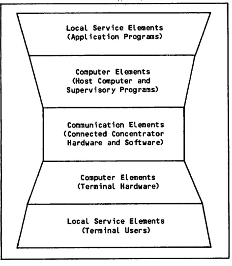
You can think of a CDC network as a hierarchy of hardware and software elements with three functional l e v e l s . E a c h f u n c t i o n a l l e v e l i m p l e m e n t s o n e o r more of the ISO/OSI protocol layers.
T h e s e p a r a t e d p o r t i o n s o f t h e s e t h r e e l e v e l s a r e s h o w n i n fi g u r e 1 - 2 . T h e o u t e r m o s t l e v e l i s t h e service network. The service network comprises the s i t e ' 8 l o c a l s e r v i c e e l e m e n t s . T h e l o c a l s e r v i c e elements include the network application programs in a host computer and the people at terminals using those programs.
Local Service Elements (Application Programs)
Computer Elements (Host Computer and Supervisory Programs)
Communication Elements (Connected Concentrator Hardware and Software)
Computer Elements (Terminal Hardware)
Local Service Elements (Terminal Users)
Figure 1-2. Element Levels Within a Network
T h e m i d d l e l e v e l i s t h e c o m p u t e r n e t w o r k . T h e c o m p u t e r n e t w o r k c o m p r i s e s t h e s i t e - a d m i n i s t e r e d local and remote computer elements. The computer e l e m e n t s i n c l u d e t h e t e r m i n a l s , a h o s t c o m p u t e r, and network software supervisory programs in a host
computer.
The innermost level is the communications network* The communications network comprises the local and remote communications elements. The communications e l e m e n t s i n c l u d e t h e c o m m u n i c a t i o n s c o n c e n t r a t o r hardware (called network processing units, or NPUs), t h e c o n c e n t r a t o r s o f t w a r e , a n d t h e l i n k a g e s ( I S O / OSI layers 2 and 3) among these elements needed to connect the isolated ends of the other levels.
To ensure proper functioning of a CDC network, you m u s t c o n fi g u r e t h e f u n c t i o n a l l e v e l s c o r r e c t l y .
Using NDL source statements, you provide the infor mation necessary to identify the hardware and soft ware elements in each level of the network to the other levels of the network. You must also estab l i s h l o g i c a l r e l a t i o n s h i p s a m o n g t h e h a r d w a r e a n d software elements.
SUPERVISORY PROGRAMS
Each functional level of the network hierarchy has c o r r e s p o n d i n g s u p e r v i s o r y s o f t w a r e . C D C p r o v i d e s
three supervisory programs:
The Network Validation Facility
The Communications Supervisor
The Network Supervisor
These supervisory programs run in a host computer a n d u s e t h e n e t w o r k d e fi n i t i o n fi l e s t o i n i t i a l i z e , m o n i t o r, a n d c o n t r o l n e t w o r k o p e r a t i o n s ( I S O / O S I l a y e r 7 ) . F i g u r e 1 - 3 s h o w s t h e a d m i n i s t r a t i v e fi l e s used by these supervisory programs.
The Network Validation Facility (NVF) uses the local configuration file in conjunction with the NOS sys
t e m v a l i d a t i o n fi l e ( VA L I D U z ) t o d e t e r m i n e w h i c h host resources terminal users are allowed to access and which applications can run in the network. NVF runs in each host in the network.
The Communications Supervisor (CS) uses information f r o m t h e n e t w o r k c o n fi g u r a t i o n fi l e t o m o n i t o r a n d c o n t r o l N P U a n d d e v i c e o p e r a t i o n s ( I S O / O S I l a y e r 5 ) . C S o v e r s e e s t h e c o n t i n u i n g o p e r a t i o n s o f t h e communication elements and the computer elements o u t s i d e o f t h e s i t e h o s t . C S c a n r u n i n o n e o r more hosts in the network*
The Network Supervisor (NS) uses information from t h e n e t w o r k c o n fi g u r a t i o n fi l e i n c o n j u n c t i o n w i t h t h e N P U l o a d fi l e t o l o a d n e t w o r k p r o c e s s i n g u n i t s . T h e i n f o r m a t i o n N S l o a d s d e t e r m i n e s t h e i n i t i a l o p e r a t i o n o f t h e c o m m u n i c a t i o n e l e m e n t s .
NS can run in one or more hosts in the network.
NETWORK ACCESS METHOD INTERFACES
All data messages pass through the Network Access Method (NAM) to ensure their integrity as they are r o u t e d a m o n g t e r m i n a l s , t h e h o s t c o m p u t e r, a n d a p p l i c a t i o n s . N A M c o n s i s t s p r i m a r i l y o f t h r e e interface programs (ISO/OSI layers 4 and 5) in the host computer:
The Peripheral Interface Program
The Network Interface Program
The Application Interface Program
T h e P e r i p h e r a l I n t e r f a c e P r o g r a m r u n s i n a h o s t c o m p u t e r p e r i p h e r a l p r o c e s s o r. T h e N e t w o r k I n t e r f a c e P r o g r a m r u n s I n t h e h o s t c o m p u t e r ' s c e n t r a l p r o c e s s o r a n d u s e s a s y s t e m c o n t r o l p o i n t ; i t i s thus able to communicate with other programs using o t h e r c o n t r o l p o i n t s . A c o p y o f t h e A p p l i c a t i o n Interface Program runs in the field length of every n e t w o r k a p p l i c a t i o n p r o g r a m , i n c l u d i n g t h e s u p e r visory programs. Figure 1-4 shows the relationships among this software.
/ * ^ S | v
[image:16.610.30.266.244.515.2]NPU LOAD
FILE
NETWORK CONFIGU
RATION FILE
LOCAL CONFIGU
RATION FILE
NETWORK SUPER
VISOR
COMMUNI CATIONS SUPER
VISOR
VALIDUz SYSTEM VA L I D A TION FILE
NETWORK VA L I D A
TION FACILITY
Figure 1-3. Supervisory Programs and File Use
HOST COMPUTER CENTRAL PROCESSOR
HOST COMPUTER PERIPHERAL PROCESSOR
" 1
-W 0 R K
r
SUPERVISORY APPLICATION
PROGRAM
AIP*
SITE-WRITTEN SERVICE APPLICATION
PROGRAM
AIP*
CDC-WRITTEN SERVICE APPLICATION
PROGRAM
AIP*
1 NETWORK ACCESS | METHOD
L
•APPLICATION INTERF
NETWORK INTERFACE
PROGRAM
PERIPHERAL INTERFACE
PROGRAM
. J
ACE PR OGRAM
Figure 1-4. The Network Access Method
T h e s u p e r v i s o r y a p p l i c a t i o n p r o g r a m i n fi g u r e 1 - 4 could be one of the three CDC-written programs shown in figure 1-3, or it could be a site-written program t a i l o r e d t o y o u r n e e d s . Yo u c a n p r o v i d e y o u r o w n n e t w o r k s e r v i c e a p p l i c a t i o n p r o g r a m s , o r y o u c a n use CDC-written service programs such as the Inter a c t i v e F a c i l i t y o r t h e R e m o t e B a t c h F a c i l i t y. T h e CDC-written network service programs are described
l a t e r i n t h i s s e c t i o n .
SIMPLE NETWORK
F i g u r e 1 - 5 s h o w s a p o s s i b l e n e t w o r k , S i m n e t . I n this simple network, a single host computer, a CDC CYBER 170 Model 176, is connected to a network p r o c e s s i n g u n i t ; t h e N P U i s a s m a l l , i n d e p e n d e n t processor. This connection consists of a CYBER 170 h o s t c o m p u t e r d a t a c h a n n e l c a b l e d t o a h a r d w a r e module (called a coupler) in the NPU. An NPU con n e c t e d t o t h e h o s t i n t h i s m a n n e r i s k n o w n a s a f r o n t - e n d N P U . T h e f r o n t - e n d N P U i n S i m n e t i s NPU1, a CDC 255x Communications Processor.
HOST COMPUTER
CYBER 170 MODEL 176
r " c s " " " 1
D ATA CHANNEL"
FRONT-END NPU (NPU1)
HOST OPERATOR
NPU OPERATOR COUPLER
r C C P I
L J
CDC 255x
REMOTE NPU (NPU2)
l C C P i
i - j
CDC 255x
T2
T3
Figure 1-5. Simnet - A Simple Configuration
The front-end NPU can support terminals and other NPUs, known as remote NPUs. Remote NPUs can also support terminals. The only remote NPU in this net work is NPU2, a CDC 255x Communications Processor.
The front-end network processing unit NPU1 supports t e r m i n a l T l , a n d t h e r e m o t e p r o c e s s i n g u n i t N P U 2 supports terminals T2 and T3. CDC provides support f o r m a n y d i ff e r e n t t y p e s o f t e r m i n a l s a n d t e r m i n a l devices, as described in sections 4 through 7.
1-4
I n t h e fi g u r e , C I i s t h e h o s t c o m p u t e r ' s s y s t e m c o n s o l e . T h e s y s t e m c o n s o l e i s n o t c o n s i d e r e d a network terminal and therefore is not defined in an N D L p r o g r a m . T h e p e r s o n a t t h e s y s t e m c o n s o l e , h o w e v e r , i s a n a d m i n i s t r a t i v e o p e r a t o r f o r t h e network.
Administrative Operators
A CDC network supports three types of administrative o p e r a t o r s :
The host operator (HOP)
The NPU operator (NOP)
The diagnostic operator (DOP)
The host operator is located at the system console for the site's host computer. The HOP can monitor a n d c o n t r o l a p p l i c a t i o n s t a t u s , m o n i t o r N P U d u m p a n d l o a d s t a t u s , p l u s p e r f o r m a l l o f t h e f u n c t i o n s o f a n N P U o p e r a t o r. T h e H O P a l w a y s h a s c o n t r o l over all of the network.
The NPU operator is located at a terminal or host computer console. The NOP can obtain and change t h e s t a t u s o f n e t w o r k e l e m e n t s , c o m m u n i c a t e w i t h terminal users, and run diagnostic tests. Each NPU can have one controlling NOP.
T h e d i a g n o s t i c o p e r a t o r i s l o c a t e d a t a t e r m i n a l serviced by the network. The DOP can monitor the status of network elements and can run diagnostic tests on an NPU. Any terminal user with permission t o l o g i n t o t h e C o m m u n i c a t i o n s S u p e r v i s o r c a n become a DOP. There can be several DOPs active at the same time.
I n S i m n e t , t h e h o s t o p e r a t o r i s l o c a t e d a t t h e system console (CI), and an NPU operator is located a t t e r m i n a l T l . B o t h a d m i n i s t r a t i v e o p e r a t o r s c o m municate with the Communications Supervisor in the
host computer.
Variants of NPU Software
Each NPU, because it is an independent processor, has its own software. The software an NPU requires t o a c c e s s t h e n e t w o r k i s c a l l e d i t s v a r i a n t . Yo u must describe each NPU's software to the supervisory p r o g r a m s . Yo u d o s o b y i d e n t i f y i n g w h i c h p r o g r a m i n i t i a t i o n c o n t r o l b l o c k ( P I C B ) w i t h i n t h e N P U l o a d file properly describes the software in each NPU.
C D C 2 5 5 x N P U s r e q u i r e l o a d i n g , c o n fi g u r i n g , a n d o p e r a t i o n a l c o n t r o l f r o m t h e s u p e r v i s o r y p r o g r a m s i n t h e h o s t . N P U s t h a t c a n l o a d t h e m s e l v e s b u t r e q u i re h o s t co n fig u r a t i o n a n d s u p e r v i s i o n t o o p e r a t e o r t h a t a r e s e l f - l o a d i n g a n d s e l f - c o n fi g u r i n g can also belong to the network.
T h e s o f t w a r e v a r i a n t u s e d i n a p a r t i c u l a r N P U d e p e n d s o n v a r i o u s a s p e c t s o f t h e n e t w o r k t o b e c o n fi g u r e d , i n c l u d i n g :
The type of NPU and host hardware in your net work (CDC or non-CDC equipment, front-end or
remote NPU, and so forth)
The network topology (connections between front-end and remote NPUs)
j j ^ * V
The types of terminals and devices the NPU must support
The software in a CDC 255x series Communications P r o c e s s o r n e t w o r k p r o c e s s i n g u n i t i s c o l l e c t i v e l y c a l l e d t h e C o m m u n i c a t i o n C o n t r o l P r o g r a m ( C C P ) . CCP can contain three types of interface programs:
A Host Interface Program (HIP)
A Link Interface Program (LIP)
One or more Terminal Interface Programs (TIPs)
A H I P i s n e e d e d o n l y i f t h e C C P v a r i a n t l i n k s a f r o n t - e n d N P U t o a h o s t c o m p u t e r ( I S O / O S I l a y e r 2 ) . A L I P i s n e e d e d o n l y i f t h e C C P v a r i a n t l i n k s a remote NPU and a front-end NPU (ISO/OSI layer 2 ) . A T I P i s n e e d e d o n l y i f t h e C C P v a r i a n t l i n k s terminals to the network or an X.25 application-to-application connection (ISO/OSI layers 2, 4, and 6).
F i g u r e 1 - 6 p r e s e n t s a n o t h e r v i e w o f S i m n e t , i l l u s t r a t i n g t h e r e l a t i o n s h i p s a m o n g t h e s e i n t e r f a c e programs. Note that terminals T2 and T3 each con n e c t t o a d i ff e r e n t Te r m i n a l I n t e r f a c e P r o g r a m . T 2 is a CDC 752, which is an asynchronous terminal; T3 is a CDC 200 User Terminal, which is a synchronous t e r m i n a l . E a c h h a s d i ff e r e n t s u p p o r t r e q u i r e m e n t s ; t h e r e f o r e , a d i ff e r e n t i n t e r f a c e p r o g r a m i s r e q u i r e d for each.
HOST
COMPUTER C1
FRONT-END NPU
HIP I
i
LIP " I • I TIP
REMOTE NPU
LIP I l I TIP
I ' T I P J
T2 CDC
752
T3 CDC 200 UT
T h e n e t w o r k s o f t w a r e c u r r e n t l y s u p p o r t s T I P s f o r fi v e g e n e r a l t e r m i n a l p r o t o c o l s . Y o u r s i t e c a n provide its own Terminal Interface Program software t o s u p p o r t u p t o t h r e e a d d i t i o n a l p r o t o c o l s ; y o u r site can also modify CDC-written Terminal Interface P r o g r a m s t o s u p p o r t l o c a l v a r i a n t s o f t h e fi v e g e n e r a l p r o t o c o l s .
PACKET-SWITCHING NETWORK
C D C n e t w o r k s o f t w a r e p r o v i d e s s u p p o r t f o r a s y n c h r o n o u s t e r m i n a l s c o n n e c t e d t o p u b l i c p a c k e t -s w i t c h i n g n e t w o r k -s ( P S N -s ) . T h i -s -s u p p o r t c o m p l i e -s w i t h r e c o m m e n d a t i o n X . 2 5 o f t h e I n t e r n a t i o n a l Te l e g r a p h a n d Te l e p h o n e C o n s u l t a t i v e C o m m i t t e e ( C C I T T ) f o r s t a n d a r d i z i n g t h e i n t e r f a c e b e t w e e n d a t a t e r m i n a l e q u i p m e n t a n d p a c k e t - s w i t c h i n g n e t w o r k s . ( P a c k e t - s w i t c h i n g n e t w o r k s a r e s o m e t i m e s
called public data networks, or PDNs.)
F i g u r e 1 - 7 s h o w s t h e p a c k e t a s s e m b l y / d i s a s s e m b l y ( PA D ) s e r v i c e , w h i c h i s o n e p a r t o f t h e i n t e r f a c e b e t w e e n t h e n e t w o r k a n d t h e d a t a t e r m i n a l e q u i p m e n t . T h i s p a r t o f t h e i n t e r f a c e I s p r o v i d e d b y
the packet-switching network.
LINE USING X.25 PROTOCOL
HOST COMPUTER
FRONT-END NPU
HOST COMPUTER
PACKET-SWITCHING NETWORK
NPU
r _ _ J - _ _
I P A C K E T | . A S S E M B LY / . . DISASSEMBLY . 'PAD) SERVICE L
FOREIGN HOST
LINE USING ASYNCHRONOUS PROTOCOL
ASYNCHRONOUS TERMINAL
Figure 1-6. CCP Interface Programs F i g u r e 1 - 7 . P a c k e t - s w i t c h i n g N e t w o r k I n t e r f a c e
Since the X.25 protocol is not symmetric, the roles played by each end of an X.25 link must be identi fi e d f o r e a c h X . 2 5 l i n e . T h e e n d s o f a X . 2 5 l i n k are the data terminal equipment (DTE) and the data circuit equipment (DCE).
A calling terminal is linked with the Communication Control Program in the NPU via a logical path called a v i r t u a l c i r c u i t . T h e s i t e m u s t s u b s c r i b e t o t h e packet-switching network for the desired number of v i r t u a l c i r c u i t s a s w e l l a s o t h e r p a r a m e t e r s ( d e s c r i b e d i n s e c t i o n 5 ) a f f e c t i n g t h e o p e r a t i o n o f the NPU-PSN interface. CDC support of this type of c o n fi g u r a t i o n i s d e s c r i b e d i n d e t a i l i n s e c t i o n 5 .
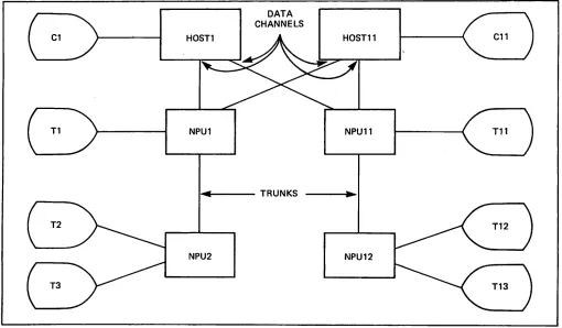
MULTIPLE-HOST NETWORK
N e t w o r k s o f t w a r e s u p p o r t s n e t w o r k s w i t h m u l t i p l e h o s t c o m p u t e r s . A s i m p l e m u l t i p l e - h o s t c o n fi g u r a t i o n i s i l l u s t r a t e d b y D u a l n e t i n fi g u r e 1 - 8 . A second host has been added to the network, connect ing to a coupler in NPU2. Both NPU1 and NPU2 are channel-connected as front-end NPUs to a local host a n d a r e c o n n e c t e d t o a r e m o t e h o s t v i a a t r u n k communication line.
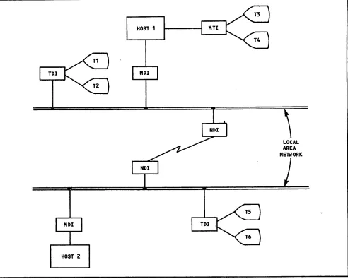
A more complicated multiple-host network concept is i l l u s t r a t e d b y M u l t i n e t i n fi g u r e 1 - 9 . N o t e t h a t each side of the figure resembles Simnet in figure 1 - 5 . I n e f f e c t , t w o e n t i r e n e t w o r k s h a v e b e e n merged. This has been accomplished by connecting each front-end processor to both hosts. Figure 1-7 shows a multiple-host network where the hosts are interconnected by an X.25 packet-switching network.
M u l t i p l e - h o s t n e t w o r k s o f f e r t h r e e f e a t u r e s t h a t are not available in single-networks. These are:
T h e a b i l i t y o f a t e r m i n a l u s e r t o c o n n e c t t o one of many hosts.
T h e a b i l i t y o f a n a p p l i c a t i o n i n o n e h o s t t o communicate with an application in one or more other hosts.
T h e a b i l i t y o f t h e N P U s i n t h e n e t w o r k t o b e l o a d e d , c o n fi g u r e d , a n d s u p e r v i s e d b y o n e o f several hosts in the network.
T h e i n s t a l l a t i o n c a n e i t h e r p r e a s s i g n t e r m i n a l users to hosts, or can allow them to select a host w h e n t h e y c o n n e c t t o t h e n e t w o r k . I n b o t h c a s e s , t e r m i n a l u s e r s c a n e i t h e r b e r e q u i r e d t o l o g i n t o the selected host or can be automatically logged in to the host.
A p p l i c a t i o n s w a n t i n g t o e s t a b l i s h c o n n e c t i o n s w i t h applications in other hosts do not need to be aware o f t h e t o p o g r a p h y o f t h e n e t w o r k . I n s t e a d , t h e i n s t a l l a t i o n m u s t s p e c i f y t h e a d d r e s s i n g a n d fl o w c o n t r o l p a r a m e t e r s t h a t t h e n e t w o r k s o f t w a r e c a n use to establish the connection. This must be done for each path that can be used for an application-t o - a p p l i c a application-t i o n c o n n e c application-t i o n .
A s p a r t o f t h e d e fi n i t i o n o f t h e n e t w o r k c o n fi g u r a t i o n , t h e i n s t a l l a t i o n a l s o d e fi n e s t h e s u p e r v i s i o n p a t h s t o h o s t s t h a t a n N P U c a n u s e t o o b t a i n i t s c o n fi g u r a t i o n a n d i t s o p e r a t o r i n t e r f a c e .
DEFINING A CDC NETWORK
When defining your network, you must specify both i t s p h y s i c a l a n d i t s l o g i c a l c h a r a c t e r i s t i c s . T h e N e tw o r k D e fi n i ti o n L a n g u a g e h e l p s y o u c r e a t e y o u r d e fi n i t i o n i n a s i m p l e a n d l o g i c a l m a n n e r . T h i s s e c t i o n p r e s e n t s t h r e e a s p e c t s o f t h e n e t w o r k t h a t must be described in your NDL program: its hard w a r e e l e m e n t s , i t s s o f t w a r e e l e m e n t s , a n d t h e logical relationships you must define among them.
HARDWARE ELEMENTS
To ensure proper operation of the network, you must c a r e f u l l y d e fi n e a l l o f i t s h a r d w a r e e l e m e n t s a n d e s t a b l i s h t h e r e l a t i o n s h i p s a m o n g t h e m . T h e c o n figurable hardware elements of the network are shown i n fi g u r e 1 - 1 0 . E a c h t y p e o f e l e m e n t i s d e s c r i b e d i n d e t a i l b e l o w.
C1 HOST1
DATA CHANNELS
HOST2
NPU1 TRUNK NPU2
Figure 1-8. Dualnet
[image:20.610.40.541.479.692.2]C1
T1
T2
T3
H0ST1
DATA CHANNELS
NPU1
TRUNKS
NPU2
H0ST11
NPU11
NPU12
C11
T11
T12
T13
F i g u r e 1 - 9 . M u l t i n e t
HOST
FRONT-END NPU
COUPLER
TRUNK
REMOTE NPU
TERMINAL DEVICE
COMMUNICATION LINES
TERMINAL
TERMINAL DEVICE
DEVICE
DEVICE
Figure 1-10. Configurable Hardware Elements
[image:21.610.66.576.45.343.2]Host Processors
A host processor is any computer mainframe that is l i n k e d t o t h e n e t w o r k t o r u n n e t w o r k a p p l i c a t i o n p r o g r a m s . H o s t c o m p u t e r s c o n t a i n t h e p o r t i o n s o f t h e n e t w o r k s o f t w a r e n e c e s s a r y f o r a p p l i c a t i o n s t o access the network.
A host can be connected through its data channels to one or more network processing unit data channel c o u p l e r s , a s w a s i l l u s t r a t e d b y t h e n e t w o r k p r o c essing units NPU1 and NPU2 of Simnet (figure 1-5), which in turn can be connected to other hosts.
No separate NDL statements exist to define a host. Hosts are assumed to be attached to couplers, so you can specify all needed host access information when you configure the couplers. Computers that access t h e n e t w o r k w i t h o u t c o u p l e r s a r e t r e a t e d b y t h e network as terminals or as foreign hosts and access the network via X.25 connections. These computers m u s t c o m m u n i c a t e t h r o u g h o n e o f t h e t e r m i n a l protocols described in sections 4 through 7.
Network Processing Units
N e t w o r k p r o c e s s i n g u n i t s c a n b e e i t h e r C D C 2 5 5 x s e r i e s C o m m u n i c a t i o n s P r o c e s s o r s o r n o n - C D C processors with compatible communication procedure s o f t w a r e . U n l e s s o t h e r w i s e q u a l i fi e d , s u b s e q u e n t r e f e r e n c e s t o n e t w o r k p r o c e s s i n g u n i t s I n t h i s manual apply to both types of equipment.
N e t w o r k s c a n c o n t a i n t w o t y p e s o f 2 5 5 x n e t w o r k p r o c e s s i n g u n i t s : t h e 2 5 5 0 ( s o m e t i m e s c a l l e d a 2550 Host Communications Processor) and the 2551. A 2550 NPU has at least one coupler and always o p e r a t e s a s a f r o n t - e n d N P U . A 2 5 5 1 c a n h a v e a coupler, but need not have one, and can be con figured as either a front-end or remote NPU.
The 2551 series Communications Processor has both a programmable micromemory and a macromemory; each m o d e l o f t h e 2 5 5 1 s e r i e s h a s v a r y i n g a m o u n t s o f macromemory, with several sizes of random access micromemory (RAM) logic. To run the current release of CCP requires 6144 words (6K) of micromemory. Because models can be modified on site, a model d e s i g n a t i o n d o e s n o t n e c e s s a r i l y c o r r e s p o n d t o a specific macromemory or micromemory configuration.
Some NPUs have a magnetic tape cassette drive and a n o p e r a t o r ' s c o n s o l e t h a t i s n o t p a r t o f t h e n e t w o r k . T h e m a g n e t i c t a p e c a s s e t t e d r i v e a n d accompanying deadman timer hardware are required if the 2551 has two couplers or is used as a remote NPU. When an NPU has a cassette drive, the drive i s u s e d t o b e g i n t h e l o a d i n g o f C C P f r o m a h o s t computer.
The cassette drive loads a copy of the system auto start module program (SAM-P) from a CDC-supplied c a s s e t t e . S A M - P i s e s s e n t i a l l y a b o o t s t r a p l o a d e r that obtains the copy of CCP appropriate for its NPU from a copy of the Network Supervisor program in a host computer.
The cassette drive can also be used to load optional o ff - l i n e h a r d w a r e d i a g n o s t i c s o f t w a r e f o r u s e w i t h
the offnet NPU console.
If the NPU has an operator's console, that console is not part of the network; it connects to a special port of the NPU and is not serviced through a com m u n i c a t i o n s l i n e a d a p t e r. T h i s o f f n e t c o n s o l e i s associated with the NPU operator.
T h e o f f n e t N P U c o n s o l e i s u s e d t o r u n o p t i o n a l o n l i n e o r o f fl i n e d i a g n o s t i c s o f t w a r e . I f t h e s i t e modifies its copy of CCP, the offnet console can be u s e d w i t h t h e i n t e r n a l Te s t U t i l i t y P a c k a g e f o r online debugging of the code.
Both front-end and remote NPUs can be connected to t e r m i n a l s t h r o u g h t h e N P U ' s i n p u t / o u t p u t p o r t s . Te r m i n a l s c a n b e l i n k e d d i r e c t l y t o t h e s e p o r t s w i t h c o m m u n i c a t i o n l i n e s , o r i n d i r e c t l y v i a a n X.25 packet-switching network.
If a network processing unit in your network is not CDC equipment, you can define it as an NPU if it r u n s s o f t w a r e c o m p a t i b l e w i t h t h e i n t e r n a l n e t w o r k protocols of CDC NPUs.
Couplers
The input/output channel from the host is connected to the front-end NPU via a hardware module known as a c o u p l e r. T h e c o u p l e r i s p h y s i c a l l y h o u s e d w i t h i n an NPU but must be configured separately because
some NPUs do not have couplers.
The coupler makes data signals to the host computer compatible with the hardware of the host and data signals to the NPU compatible with the NPU. An NPU can have one or two couplers, each connected to a h o s t c o m p u t e r. To s u p p o r t a c o u p l e r, a C D C N P U must be loaded with a CCP variant that includes the Host Interface Program.
Trunks
A front-end NPU can be connected to another NPU by a communication line called a trunk. You can con
figure only one trunk between any pair of NPUs, but y o u c a n c o n fi g u r e m u l t i p l e t r u n k s c o n n e c t i n g d i f ferent NPUs to any single NPU.
To support trunks, C C P v a r i a n t t h a t Program.
CDC NPU must be loaded with a i n c l u d e s t h e L i n k I n t e r f a c e
Communication Lines
The network software supports lines for synchronous t e r m i n a l s a n d f o r a s y n c h r o n o u s t e r m i n a l s . T h e s e l i n e s c a n b e s w i t c h e d ( a l s o c a l l e d d i a l u p ) o r d e d i c a t e d ( a l s o c a l l e d h a r d w i r e d ) . Yo u c a n c o n
fi g u r e l i n e s w i t h s p e e d s o f u p t o 5 6 0 0 0 b i t s p e r second (b/s) as one of nine general line types.
Each line type corresponds to a set of characteris tics used by a CDC or non-CDC communications line adapter (CLA). There are three types of CDC com munications line adapters:
M o d e l 2 5 6 0 s e r i e s s y n c h r o n o u s C L A s , u s e d t o s u p p o r t l i n e s c o n e c t i n g m o d e 4 t e r m i n a l s , I B M 2780 or IBM 3780 bisynchronous terminals, HASP p r o t o c o l t e r m i n a l s , o r 3 2 7 0 b i s y n c h r o n o u s
terminals to the NPU.
Model 2561 series asynchronous CLAs, used to s u p p o r t l i n e s c o n n e c t i n g t e l e t y p e w r i t e r -compatible or IBM 2741--compatible terminals to the NPU.
M o d e l 2 5 6 3 s e r i e s h i g h - l e v e l d a t a l i n k c o n t r o l (HDLC) CLAs, used to support trunks connecting o t h e r N P U s o r l i n e s . c o n n e c t i n g a s y n c h r o n o u s terminals, NPUs with hosts, or foreign hosts to the NPU through X.25 packet-switching networks.
SOFTWARE ELEMENTS
N e t w o r k s o f t w a r e r u n s i n t w o e n v i r o n m e n t s : t h e h o s t a n d t h e N P U . S t a n d a r d C D C s o f t w a r e r u n s i n b o t h t o s u p p o r t m a n y n e t w o r k c o n fi g u r a t i o n s . Yo u r s i t e c a n a l s o p r o v i d e i t s o w n s o f t w a r e t o s u p p o r t o t h e r t y p e s o f e q u i p m e n t a n d o t h e r u s e s . T h e characteristics of software not provided by CDC are u n k n o w n , a n d t h e r e f o r e a r e n o t a d d r e s s e d b y t h i s manual.
Terminals Data Structures and Flow A terminal is a single point of access between one
or more devices and a communication line. The cur r e n t n e t w o r k s o f t w a r e p r o v i d e s s u p p o r t f o r fi v e basic types of terminals:
Asynchronous terminals, such as the CDC 751, u s i n g e i t h e r a s y n c h r o n o u s p r o t o c o l o r X . 2 5 p r o t o c o l
Mode 4 protocol synchronous terminals, such as the CDC 200 User Terminal
M u l t i l e a v i n g b i s y n c h r o n o u s t e r m i n a l s , s u c h a s IBM Corporation's HASP workstations
B i n a r y s y n c h r o n o u s t e r m i n a l s , s u c h Corporation's 2780 or 3780 terminals
B i n a r y s y n c h r o n o u s t e r m i n a l s Corporation's 3270 terminal
s u c h a s IBM
IBM
Y o u c a n c o n fi g u r e u p t o t h r e e m o r e t y p e s o f terminals with a site-provided TIP for each type.
Terminals are grouped into classes by their specific h a r d w a r e c h a r a c t e r i s t i c s . A t e r m i n a l c l a s s p a r a m eter is used to define some physical characteristics of the terminal and to determine the default values o f o p e r a t i o n a l c h a r a c t e r i s t i c s . T h e n e t w o r k s o f t w a r e s u p p o r t s 1 8 C D C - d e fi n e d t e r m i n a l c l a s s e s . T h e s e t e r m i n a l c l a s s e s a r e d e s c r i b e d i n g r e a t e r detail in sections 4 through 6.
If you provide your own support software, you can use features of the Network Definition Language to d e fi n e u p t o f o u r a d d i t i o n a l t e r m i n a l c l a s s e s . C D C c a n n o t a n t i c i p a t e t h e s u p p o r t r e q u i r e d f o r s u c h terminals, and thus cannot document such support. Yo u c a n fi n d i n f o r m a t i o n p e r t i n e n t t o d e fi n i n g y o u r own terminals in sections 4 through 7.
Devices
E a c h t e r m i n a l i n c l u d e s o n e o r m o r e s e p a r a t e l y configured devices that perform both input and out p u t , i n p u t o n l y , o r o u t p u t o n l y . F o r X . 2 5 a n d asynchronous protocols, a device such as a console i s a te rmi n a l . F o r s y n c h r o n o u s p r o to c o l s, a d e v i c e such as a console is only a portion of a terminal.
An interactive device such as a console can perform both input and output, and its user can participate e a s i l y i n d i a l o g w i t h h o s t s o f t w a r e . A p a s s i v e o r batch device such as a card reader or line printer c a n p e r f o r m o n l y o n e - h a l f o f s u c h d i a l o g . I n t e r a c t i v e a n d p a s s i v e d e v i c e s u s e d i f f e r e n t t y p e s o f data structures and paths through the network.
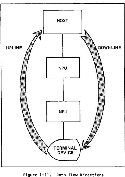
Data flow in the network is defined from the view p o i n t o f t h e h o s t c o m p u t e r . D a t a c o m i n g t o t h e h o s t i s s a i d t o b e t r a v e l i n g u p l i n e ; d a t a m o v i n g a w a y f r o m t h e h o s t i s s a i d t o b e t r a v e l i n g d o w n l i n e . T h i s c o n c e p t i s s h o w n i n fi g u r e 1 - 11 .
HOST
UPLINE DOWNLINE
Figure 1-11. Data Flow Directions
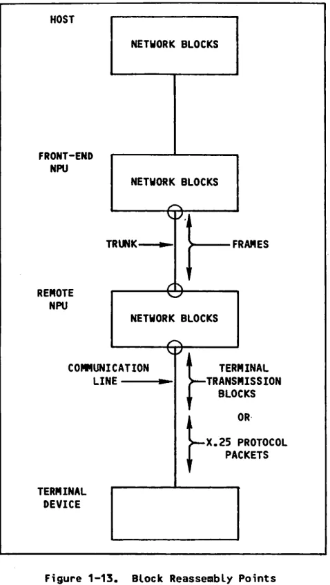
Upline and downline information within the host and NPUs is always grouped into physical network blocks. N e t w o r k d a t a b l o c k s a r e g r o u p e d i n t o l o g i c a l m e s
sages. Messages exchanged between an NPU and a d e v i c e c a n a l s o b e g r o u p e d i n t o p h y s i c a l t r a n s mission blocks of one or more logical lines. Figure
1-12 shows these concepts.
A s i n g l e n e t w o r k d a t a b l o c k i s a c o l l e c t i o n o f c h a r a c t e r b y t e s , a n a l o g o u s t o a c l a u s e i n E n g l i s h . I t i s a p a r t i a l l y i n d e p e n d e n t u n i t o f i n f o r m a t i o n and might need to be used with other blocks to form a message.
[image:23.610.334.575.228.570.2]