WRITE EQUALIZATION IN HIGH-LINEAR-DENSITY MAGNETIC RECORDING
Richard C. Schneider
IBM General Products Division, Tucson, Arizona 85744
ABSTRACT
For many years, equalization has been used on the read side of a
magnetic-recording channel to obtain a desired signal shape at the detector. Compensation on the write side has, for the most part, been limited to moving transition locations to offset read-signal peak shifts. This paper presents a new method of equalization on the write side through the addition of pulses at strategic locations of the write waveform. The resulting write current
continues to be a two-level signal, so ac bias is not required. A linear transfer function can be derived for these write equalizers. This enables the recording-channel designer to more optimally partition the equalization
between the write and read sides. The principal benefit of write equalization is that the read-flux-amplitude differences between high and low densities are significantly reduced. This enables maximum use of the linear operating
each zero of the run-length code; in general, however, any number of additional pulses may be used.
Subsequent sections show how write equalization is implemented through the use of timing and block diagrams, and how a linear transfer function is derived from the block diagrams. The relationship between the write-equalizer
frequency response and the position of the added pulses is also explored. The section on test results presents data indicating the linearity of the overall recording channel. The waveshapes of the resulting read signals are also given in this section. The conclusions summarize the major features and advantages of the 3480 write =qualizer.
DESCRIPTION OF WRITE EQUALIZATION
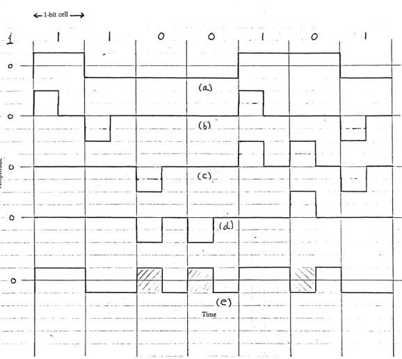
In conventional NRZI (non-return-to-zero IBM), transitions are made at the start of a bit cell for a one, and a zero is the absence of a transition [11]. This section shows that a write-equalized waveform can be obtained by passing NRZI data through a digital filter that adds pulses to the NRZI signal. This demonstrates that the write-equalization process is linear and that a linear transfer function can be derived. Three examples are given: the first uses the 3480 filter parameters; the second uses a change in the position of the added pulses; and the third uses a change in width of the added pulses.
Refer to the timing diagram of Fig. 1. These waveforms represent the outputs of the digital filter blocks shown in Fig. 2, where D is a delay of half a bit period, Q=O and P=R=2. The waveform of Fig. l(a) represents conventional NRZI write current. The desired write-equalized waveform shown in Fig. lee) is the
(1)
which simplifies to
G1(0)
=
[0(1-0)J/(1+0) (2)The first 0 in the numerator can be dropped, because it represents a constant time delay. The delay does not affect the write-equalizer magnitude response or the shape of the write current or read signals. This yields
G1(0)
=
(1-0)/(1+0) (3)T o ge t th t e rans er unc lon ln f f t · . th f e requency omaln, e d · -jwT/2. lS su s b t·t t d 1 u e
for 0, where T is the time of a single-bit period. This yields
(4)
After some trigonometric manipulations, we obtain
Gr(w)
= j tan (wT/4). (5)In a similar manner, transfer functions can be derived for different pulse widths, pulse positions, or number of added pulses for each zero. Consider
the case where the added half-bit-wide pulses are centered between the normal NRZI transitions. This is equivalent to Q=~ and P=R=2 in the block diagram of Fig. 2. The following transfer function can be derived:
G2(w) = (2 sin wT/8 sin 3wT/8)/(cos wT/4) (6)
As in Eq.(3), a constant time-delay term has been dropped in the derivation of Eq. (6) .
The write-equalized-current waveforms shown so far in this paper are
continuous. When a thin-film write head with a small number of turns is used, the current may be pulsed to reduce power dissipation. This can be done by sampling the continuous waveform of Fig. l(e) twice each bit period. The resulting write current has an RZ (return to zero) appearance, as shown in Fig. 5. As long as the flux bubble produced by each pulse spans several bit periods, the resultant recorded flux is essentially identical to that produced by a continuous current. In the remainder of this paper, the continuous
convention is understood. The reader should recognize that a pulsed write current can be used for all the write equalizers described, provided that the flux-bubble dimensions are correct.
TEST RESULTS
The block diagram of Fig. 2 and the transfer functions of Eqs.(5), (6), and (7) demonstrate that the write-equalizer circuit itself is a linear digital filter. It is equally important to determine whether the entire recording channel is linear. In the case of the digital magnetic-recording channel, a restricted sense of linearity is used. A channel is defined as linear when
for all j (8)
where W.(w) is the Fourier transform of the write current for an arbitrary
J
data sequence, Rj(w) is the transform of the resulting read signal, and Gj(w) is the calculated transfer function [12].
When a write equalizer with transfer function WEQ(w) is used, it is important that the overall measured transfer function, GT(w), obey the following
equation:
SUMMARY AND CONCLUSIONS
The 3480 write equalizer belongs to a class of write equalizers in which pulses are added to the NRZI data for each zero to be recorded. Linear transfer functions can be derived for all equalizers in this class. The magnitude and phase of the transfer function can be varied by changing the added pulse position, the pulse width, or the number of added pulses for each zero. It has been shown that the overall recording channel remains linear. This enables the designer to partition the needed equalization between the write and read sides of the recording channel.
This type of write equalizer is ideally suited for the 3480 read/write head. The thin-film write head has a low inductance that allows the use of the
narrow-equalized current pulses. The resulting read signal has a uniform amplitude that permits maximum use of the linear region of the
10. D. H. Veillard, "Compact Spectrum Recording, A New Binary Process Maximizing the Use of a Recording Channel," IEEE Trans. Mag., MAG-20, No.5, September 1984, pp.891-893.
11. B. E. Phelps, "Magnetic Recording Method,"
u.s.
Patent 2,774,646 (1956).12. M.
K.
Haynes, "Experimental Determination of the Loss and Phase Transfer Functions of a Magnetic Recording Channel," IEEE Trans. Mag., MAG-13, September 1977, pp.1284-1286..;;- I-bit cell---,)
o
o
o
o
(a..)
o
Cbt
.. - 0
_( d.) _ ______ ._
.--.. _- .... --.. i - - - / . - - .. - -.. -_ ... -.. - 1--:0~./':-:-//-'·. v~</
.
... - 0
f---4.~/~~.'---_i
'----....j ... - - - . - - -r-.",.".
...;'-.'.;...~_ ... __ _ .. _ ... ~_._. . .. __ : __ .. ____ . __ ~ ... ____ (e) __
.. __ .. ___ . _____ L __
Ti~ ____ . ____ .. _______ _~.~
\.
.. ." ~~..-. _. --..
Figure 1
~
[image:7.615.25.603.62.578.2]-i
PLOT (MAC2 AND MAG AND MAC3 AND ONE) US WW
COpy
4 ..
2
..
(b)
G-~t(,J)~,""
/
I
~l·bit cell~
.. I
... I
___ 0 ... ...
0
.1._ .... _
....
0,.1
r - - - . , ... - .... - ... - .. __ .... _ ... _ . . . ... , . - - - + - - - . ... _. c .•..•... _ • . . •
_-f - - - + - - - - : - - - 1 r - - - i ... ... . ... - .... 1 - - - 1
... _ ... _. (0-)
r - - - j ... -.~--, r---1 ... ... . ..-.
..
L---~ . .•... .. - ... . . . ... 1---'
. .. .. ... ~. ~_.. .... (b)
i
,i
I
: Q) •
:'0
I i '
:t
r1
n" .... " .'... .... ... ... . .. : ...
1
n .
n
n
.< -'--'-I - . L . . . . J - _ . t-t-u
-"u..,---..
- - i -.. _U...,--,-,U,---
...
_-t--;-u-..·~
U ....
+-'--. . - . 1 . . .·-'--!-~~J-
...
"""""'-U -...+--, +--, (c)
.-. ~-... -. -- - ... _ .. - -._-_.--- .-"." ..
. n
n
.. : ... rt . .
...
· c . . ~n
... n
·.rl
n
u
u
u
...
u
u u ...
(~) . . .
t
o
./ ./
J
I
! I
/
0.4 1.6
Normalized frequency - 7
t
All ones
1.2