Service Information Manual
HP 9000 Series 300 Computers
Models 330/350
HP Part Number 98562-90030
FIIOW
HEWLETT
a!1!.II
PACKARD
Hewlett-Packard Company
NOTICE
The information contained in this document is subject to change without notice.
HEWLETI-PACKARD MAKES NO WARRANTY OF ANY KIND WITH REGARD TO THIS MANUAL, INCLUDING, BUT NOT LIMITED TO, THE IMPLIED WARRANTIES OF MERCHANTABILITY AND FITNESS FOR A PARTICULAR PURPOSE. Hewlett-Packard shall not be liable for errors contained herein or direct, indirect, special, incidental or consequential damages in connection with the furnishing, performance, or use of this material.
WARRANTY
A copy of the specific warranty terms applicable to your Hewlett-Packard product and replacement parts can be obtained from your local Sales and Service Office.
Copyright 1986 Hewlett-Packard Company
This document contains proprietary information which is protected by copyright. All rights are reserved. No part of this document may be photocopied, reproduced or translated to another language without the prior written consent of Hewlett-Packard Company. The information contained in this document is subject to change without notice.
Restricted Rights Legend
Use, duplication or disclosure by the Government is subject to restrictions as set forth in paragraph (b)(3)(B) of the Rights In Technical Data and Software clause in DAR 7-104.9(a).
Copyright 1980, 1984, AT&T, Inc.
Copyright 1979, 1980, 1983, The Regents of the University of California.
This software and documentation is based in part on the Fourth Berkeley Software Distribution under license from the Regents of the University of California.
Printing History
New editions of this Jnanual will incorporate all material updated since the previous edition. Update packages may be issued between editions and contain replacement and additional pages to be merged into the manual by the user. Each updated page will be indicated by a revision date at the bottom of the page. A vertical bar in the margin indicates the changes on each page. Note that pages which are rearranged due to changes on a previous page are not considered revised.
The manual printing date and part number indicate its current edition. The printing date changes when a new edition is printed. (Minor corrections and updates which are incorporated at reprint do not cause the date to change.) The manual part number changes when extensive technical ehanges are incorporated.
December 1986 ... Edition 1
Notices
Radio Frequency Interference Statements
Federal Communications Commission Radio Frequency Interference Statement
(U.S.A. Only)
The Federal Communications Commission (in Subpart J of Part 15, Docket 20780) has specified that the following notice be brought to the attention of the users of this product.
Warning: This equipment generates, uses, and can radiate radio frequency energy and if not installed and used in accordance with the instructions manual, may cause interference to radio communications.
It has been tested and found to comply with the limits for a Class A computing device pursuant to Subpart J of Part 15 of FCC rules, which are designed to provide reasonable protection against such interference when operated in a commercial environment. Operation of this equipment in a residential area is likely to cause interference in which case the user at his own expense will be required to take whatever measures may be required to correct the interference.
VCCI Statement (Japan Only)
L O)~
@
,j:, ~-ft'tff~~@ (~I~tili~ ~cis
~'I""[ ~m ~ tL ~«~ 'tff~~i!i) ~~I~~~~O).~.~~~~§~~LkM~~m~@~.~.~~~m~thh
~~ (V eel) £~ ~c ~ 1:5- L ""[ is ~i
-to
fJt
--:> ""[,{t'::8
tili ~ i t: ,j: i-0) ~ ~ L t: tili ~ ~ ~ ffl-t
~ ~. ::;:/;t, Tv
1::" :/3 /I
5t
ft~ ~ ~ ~c
5t
f§"
~! ~ ~13-.:Z
~ L ~ fyi £t ~ i-t
0~
m m
B~ ~ ~cfJt
-:> ""[ 1£ L ~ 'I ~ ~m
~ 'I ~ L ""[ F ~ ~ 'I 0Manufacturer's Declaration (Germany Only)
Funkentstorung Deutschland HersteUerbescheinigung
Hiermit wird bescheinigt, daB das Gedit/System HP 9000 Modell 318M (Einstiegsmodell eines monochromatischen Arbeitsplatzrechners) in Ubereinstimmung mit den Bestimmungen der Postverfiigung 1046/84 funkentstort ist.
Der Deutschen Bundespost wurde das Inverkehrbringen dieses Gerates/Systems angezeigt und die Berechtigung zur Uberpriifung der Serie auf Einhaltung der Bestimmungen eingeraumt.
Safety Considerations
WARNINGs, CAUTIONs, and Notes
WARNINGS, CAUTIONS and Notes are used in this manual to alert users to important situ-ations. They are used as follows:
• WARNINGS contain information which, if not observed, could result in injury to person-nel or loss of life.
• CAUTIONS contain information which if not observed, could result in damage to or destruction of equipment.
• Notes contain information that will assist you in accomplishing the job.
WARNING
The power supply is hazardous to personnel. Extreme care must be taken when connecting voltmeter probes to the test points. Turn otT the unit and remove the power cord before connecting or removing test probes.
CAUTION
Integrated circuits on PC boards are susceptible to damage by electro-static discharge. Extreme care must be taken when handling printed circuit boards. Use an Anti-static Workstation.
Note
Hewlett-Packard supports field repair of these products only to the board or assembly level. Component level information and repair is not within the scope of this manual, nor available.
Information Locator
Finding Service Information
On the next page is a Service Information Locator. It shows where to find a variety of subjects dealing with servicing these products. To l:lse this table, first find the type of information you need to reference in the left-hand column. Next, move to the right in that row to a referenced chapter number. Last, move up the column with the information's referenced chapter to the top. Across the top are manual titles and part numbers that have the information documented.
Chapter identifiers in the Locator use the following codes:
Chapter Number:
Appendices:
Numbers, such as 2. Inclusive chapters, such as 4-6.
Letters, such as A for Appendix A.
Entire Manual: All
Varies:
*
(Check Table of Contents or Index.)In some cases, two or more references will be shown for a given infonnation type. You should check all references to be sure you get the specific information you need.
For example, suppose you need to find out what the Repair Philosophy is for the Model 318M Workstation's SPU. Locating "Repair Philosophy" in the left-hand column, and moving to the right in that row, you'll notice that this information is in "Chapter I" of a manual. At the top of this column is the nlanual's abbreviated title. Chapter 7 in this manual lists manual titles and part nunlbers for service information.
Service Information Locator
Manuals identified in this locator are abbreviated by their initials:
81M Service Information Manual
8HB Service Handbook
CRM Configuration Reference Manual
TTM: Series 300 Test Tools Manual
8PM Site Preparation Manual
IRM Installation Reference Manual
PIN Product Installation Note
TD8 Technical Data Sheet/Price List
Service Information Locator
Service Information SIM SHB CRM TTM SPM IRM PIN TDS
Assembly replacement 2
Block diagrams 1,2 9
Booting Operating Systems 4
Computer tests 1,5 2 1, 2, 3
Configurations 1 3 All All
CS/80 tests 1,5 5 4
Electrical requirements 1 1 3, A
*
Environmental requirements 1 2 4, A
*
Functional descriptions 3
HP-HIL device tests 2, 3
Installation 2 2 All All All All
I/O Bus architecture 1,3
Monitors 1 3 All A 1
*
People who can help 1
Options / Accessories 1,3 3 All All All
*
Ordering spare parts 6 8
Part numbers 6 8 All
Peripherals 1 3 All
*
Preventive maintenance 2
Product information 1 1 All All All All All
Product numbers 1 1,3 All A All
Reference material 7 10
*
All AllSelf-tests 4, 5 5 1,2
Service notes 1 11
Site preparation 2 All
System Functional Tests 1,5 5 1,3
Systems 1 3 All All
*
Troubleshooting 5 4 All
Turn-on 3, 4 4, 5 2
Table of Contents
Service/Hardware Information
Chapter 1: Product Information
Introdllction. . . .. 1
Workstations . . . .. 1
Systenl Configurations. . . .. 1
FeatlLres . . . .. 3
Performance. . . .. 4
Hard"ware . . . .. 5
CPU _. MC68020 ... 5
Bus Architecture ... 5
Motherboard/Backplane. . . .. 6
]{ey boards . . . .. 7
HP 9000 Hardware Compatibility . . . .. 7
Operating Systerns . . . .. 9
IIP-UX 5.2 ... 9
]3ASIC~ 5.0 ... 9
]::>ascal :3.2 . . . .. 9
Software Co:mpatibility .... . . .. 9
Product Identification . . . .. 10
Product Identification Terms . . . .. 10
Serial Numbers ... 10
Hardware Terminology ... 11
Software Terminology ... 12
Hardware Support Documentation .... . . .. 12
Service Information Manual . . . .. 13
Service Handbook. . . .. 14
Test Tools Manual ... 15
Service Notes. . . .. 15
Installation Notes. . . .. 15
Series 300 Configuration Reference Manual ... 16
Site Preparation Manual. . . .. 16
Installation Reference ... 18
Specifications. . . .. 19
:Electrical . . . .. 19
Environnlental . . . .. 19
Electromagnetic Interference ... 20
Regulatory Requirements ... 20
:Physical ... . . . .. 20
Shipping Information. . . .. 20
Model 350 Processor Board ... 21
Model 330 Processor Board ... 22
Memory ... 22
DIO-II I/O Bus ... 23
System Interface Board . . . .. 23
HP-HIL and Video Accessories ... 24
Hewlett-Packard Support ... 25
Repair Philosophy ... 25
Repair Services . . . .. 25
Hardware Support Services ... 26
Operating Systems Support . . . .. 26
Chapter 2: Assembly Replacement Introduction ... , . . . .. 27
Tools Required ... 27
Access Flow Chart . . . .. 27
Parts DiagraIns . . . .. 30
Safety Precautions ... 32
Electrical Precautions ... 32
System Board Installation. . . .. 32
Electro-Static Discharge Precautions ... 33
Assembly Replacement Procedures ... 34
Overview ... 34
Fllse ... 35
HP-HIL Devices ... 35
Systenl Bus .... . . .. 35
Processor Board ... . . .. 36
Video Boards. . . .. 36
Interface Cards . . . .. 36
Add-On Boards. . . .. 37
D I 0 Accessory Cards. . . .. 38
Power Supply ... 39
Top Cover ... 41
Front Panel .. . . .. 43
Fans ... 44
DIO Card Cages. . . .. 45
DIO Backplane ... 47
Fan Housing. . . .. 48
Motherboard . . . .. 4~8 Card Guides ... 50
Chapter 3: Functional Description Introduction ... 51
Computer Overview ... 51
Expander Overview ... 51
Computer Architecture ... 51
Computer Packaging ... 54
System Implementation. . . .. 54
Unsupported Accessories ... 57
Model 350 Processor Board ... 57
Model 3:~0 Processor Board ... 57
Model 350 System Bus ... 57
Menlory Boards ... 57
System Interface Board. . . .. 59
Monitor Compatibility. . . .. 59
Direct-Connect Expanders ... 60
DIO Adapters ... 62
Power Supply ... 64
Introduction ... 64
Inpllt Section. . . .. 67
Rectification and Switching Control Circuits ... 68
Power Supply Regulators ... 68
Protection and Reset Circuits ... 69
Power Distribution ... 69
Motherboarcl . . . .. 71
Introcluction. . . .. 71
F'unctions . . . .. 71
HP 98242 DIO Backplane Board. . . .. 73
Introduction. . . .. 73
F'unctions . . . .. 73
Model ~{50 Processor Board ... 74
Introciuction. . . .. 74
Central Processing Unit ... 74
C:;oprocessor . . . .. 74
rviemory Management Unit ... 74
Translation Tables .. . . .. 77
Translation Lookaside Buffer . . . .. 77
(~ache ... 77
Boot ROM and Self-Test LEDs . . . .. 78
Model ~3:30 Processor Board ... 79
lntro(iuction. . . .. 79
Central Processing Unit ... 79
IV1emory ~anagelnent Unit. . . .. 79
On- Board RAM ... 80
Bus Architecture. . . .. 84
lntro(iuction ... 84
Model :350 System Bus ... 84
DIO and DIO-II Bus ... 84
RAM[ Boards ... 86
Introduction. . . .. 86
RAM Architecture ... 86
RAM Address and Size . . . .. 90
]=tAM (~lock . . . .. 90
Board Select ... 90
\.\-7rite (:ycle . . . .. 90
Read Cycles. . . .. 90
l\1odel :350 Systenl Bus Data Transfers. . . .. 90
RAM Configuration ... 91
Video I30ar(is . . . .. 93
Intro(iuction . . . .. 93
'Vi(ieo RAM . . . .. 96
Color ~/Iapping ... 96
Display Controller ... 96
Frame Buffer Controller ... 97
Video Output ... 97
Display RAM Control ... . . . .. 97
Interrupt Structure. . . .. 97
Identification and Font ROM ... 98
Clocks and Tilning . . . .. 98
System Interface Board . . . .. 99
Introduction. . . .. 99
Direct Memory Addressing . . . .. 102
LAN Interface. . . .. 102
RS-232 Interface. . . .. 10~3 HP-IB Interface. . . . .. 104
Configuration Switches ... . . .. 104
High-Speed Disc Add-On ... lOG HP-HIL Devices ... 109
Introduction. . . .. 109
Link Controller. . . .. 109
HP-HIL Cables. . . .. 111
Device Controller . . . .. 112
Display Compatibility Interface. . . .. 11:3 Introduction. . . .. 11:3 Video Card ... 11:3 Graphics Card ... , 11G Chapter 4: Boot ROM Functions Introduction. . . .. 119
Power-Up Sequence ... 119
Power-up Overview ... 119
Configure Mode Software Override ... 124
Force Long Memory Test ... 125
Continuous Self-Test ... 125
50 or 60 Hz CRT ... 12G The Human Interface. . . .. 127
Output Devices ... 127
Input Devices ... 127
Remote Human Interface ... 1:31 Self-Test . . . .. 13:3 Hardware Initialization Support. . . . .. 1:3:3 Assembly Self-Test Support. . . .. 1:3:3 Tests Performed by the Boot ROM ... 13:3 Memory Tests . . . .. 140
Booting Operating Systems ... 142
Boot System Selection . . . .. 142
Unattended Operation. . . .. 142
Attended Operation. . . .. 142
Boot System Priority Control ... 14G Default Mass Storage Variable ... 147
Supported Boot Configurations ... 147
Booting From The SRM ... 149
Chapter 5: Troubleshooting
Introduction. . . .. 151
Analytic Troubleshooting ... 151
Materials Required ... 151
Test LED Displays. . . .. 151
Troubleshooting Procedures. . . .. 152
Systenl Level. . . .. 152
Computer/Expander Troubleshooting ... 152
Inoperative Unit Procedure ... 154
Live Unit Procedure. . . .. 155
MiniInum Configuration ... 155
Functional Unit Troubleshooting ... 157
Intermediate Configuration. . . .. 157
Test 'Tools ... 159
()verview ... 159
Computer Tests. . . .. 159
Systenl Functional Tests . . . .. 159
CS / 80 Exercisers ... 159
Package Contents . . . .. 160
Self-Test . . . .. 161
Failure Indications 161 Chapter 6: Parts Lists Replacement Parts Information ... 167
Introduction. . . .. 167
Cooperative Support Program ... 167
Exchange Parts. . . .. 167
Parts Lists . . . .. 168
Static-Free Bags. . . .. 168
Labels ... 168
Computer Electrical Parts ... 168
Computer Case Parts. . . .. 170
Expander Case Parts Diagram . . . .. 172
HP 98570A and 98568A Opt. 132 Expander. . . .. 173
External Cables. . . .. 174
HP-HIL Devices 175 Chapter 7: References IntroductioIl. . . .. 177
Service Information Locator . . . .. 177
Localized Systenl Identification . . . .. 177
Related Hardware Documentation. . . .. 179
Hardware Support Documentation ... . . . .. 179
Installation Manuals/Notes ... 180
List of Illustrations
Chapter 1: Product Information
Figure 1-1. Model 350 Typical Workstation ... 2
Figure 1-2. Model 330 Typical Workstation ... 2
Figure 1-3. Model 330/350 Computer I/O Architecture ... 5
Figure 1-4. Model 350 System Slot Diagram ... 6
Figure 1-5. Direct-Connect Expanders Diagrams ... 8
Chapter 2: Assembly Replacement Figure 2-1. Assenlbly Access Flow Chart. . . .. 28
Figure 2-2. Computer Exploded Diagram ... 30
Figure 2-3. Expander Exploded Diagram. . . .. 31
Figure 2-4. Hardware Orientation. . . .. 34
Figure 2-5. Power Supply Cover Screws. . . .. 39
Figure 2-6. Power Supply Grounding Tab Screws ... 39
Figure 2-7. ON-OFF Switch Shaft Guide Removal ... 40
Figure 2-8. ON-OFF Switch Shaft Connection ... 40
Figure 2-9. Expander to Computer Attaching Screws. . . .. 42
Figure 2-10. Releasing the Front Panel Catches ... 43
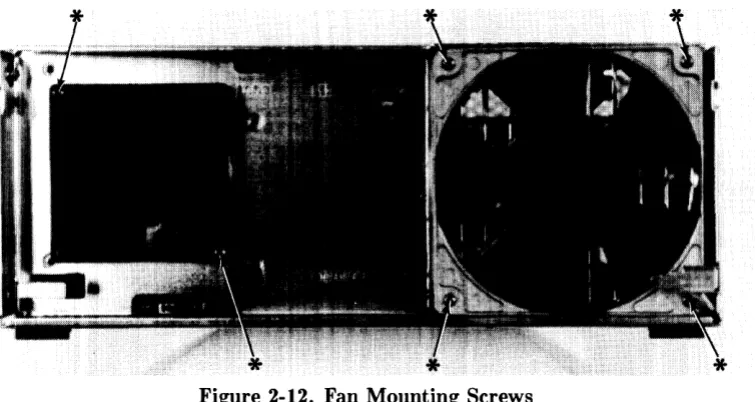
Figure 2-11. Fan Wire Connectors ... 44
Figure 2-12. Fan Mounting Screws ... 45
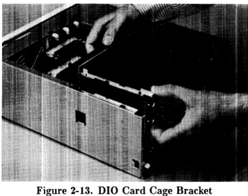
Figure 2-1:~. DIO Card Cage Bracket. . . .. 46
Figure 2-14. DIO Card Cage Screws ... 46
Figure 2-15. Fan Housing Screws ... 48
Figure 2-16a. Computer Motherboard Fasteners ... 49
Figure 2-16b / c. Expander Motherboards Fasteners. . . .. 50
Chapter 3: Functional Description Figure 3-1. Model 330/350 Architecture Diagram ... 52
Figure :3-2. Model 330/350 Block Diagram ... 53
Figure :3-3. Model 330/350 SPU Configuration ... 56
Figure :3-4. Model 330/350 RAM Configurations ... 58
Figure 3-5. Computer/Expander Back Panels ... 61
Figure :3-6. HP 98242A 4-Slot Adaptor Diagram . . . .. 62
Figure :~-7. HP 98242B 2-Slot Adaptor Diagram ... 63
Figure :3-8. Computer/Expander Power Supply . . . .. 6.5 Figure :3-9. Power Supply Block Diagram ... 66
Figure :3-10. Computer Power Distribution ... 69
Figure 3-11. Expander Power Distribution ... 70
Figure 3-12. Computer/Expander Motherboards ... 70
Figure :3-13. Model 350 Processor Board ... 75
Figure :3-14. Model 350 Processor Board Diagram ... 76
Figure :3-15. Model 330 Processor Board. . . .. 82
Figure 3-16. Model 330 Processor Board Diagram ... 83
Figure 3-17. HP 98258A 4 Mbyte RAM Controller Board ... 87
Figure 3-18. HP 98258B/C 4/12 Mbyte Add-On Board ... 88
Figure 3-19. RAM Assembly Block Diagram ... 89
Figure 3-20. Typical Video Board. . . .. 94
Figure 3-21. Typical Video Board Block Diagram ... 95
Figure 3-22. System Interface Board ... 100
Figure 3-23. System Interface Board Diagram ... 101
Figure 3-24. High-Speed Disc Add-On Board. . . .. 106
Figure 3-25. High-Speed Disc Add-On Board Diagram. . . .. 107
Figure 3-26. HP-HIL Link Controller Diagram ... 109
Figure 3-27. HP-HIL Frame Structure ... 111
Figure 3-28. HP-HIL Cable Connector ... 111
Figure 3-29. HP-HIL Device Controller Diagram ... 112
Figure 3-30. Display Compatibility Video Card. . . .. 114
Figure 3-31. Display Compatibility Video Diagram ... 115
Figure 3-32. Disp. Compatibility Graphics Card ... 117
Figure 3-33. Disp. Compatibility Graphics Diagram. . . .. 118
Chapter 4: Boot ROM Functions Figure 4-1. Example Configure Mode Display ... 124
Figure 4-2. Config'ure Mode 50/60 Hz Display ... 126
Figure 4-3. Boot ROM Output Device Selection ... 128
Figure 4-4. Boot ROM Input Device Selection ... 129
Figure 4-5. Example Self-Test Error Display. . . .. 139
Figure 4-6. Example Attended Mode Display ... 143
Figure 4-7. Example Boot Display with Errors ... 149
Chapter 6: Parts Lists Figure 6-1. Computer Case Parts Diagranl ... 170
Figure 6-2. Expander Case Parts Diagram ... 172
List of Tables
Chapter 1: Product Information
Table 1-1. Model 330/350 Computer Features ... 3
Table 1-2. HP-HIL Devices ... " 24 Table 1-3. Video Accessories ... 24
Chapter 3: Functional Description Table 3-1. Voltage Ranges and Fusing ... " 67 Table 3-2. Mode1330/350 RAM Boards ... 86
Table 3-3. HP 98258A/B/C RAM Configuration ... " 91 Table 3-4. Example Model 350 RAM Configurations ... 92
Table 3-5. Example Model 330 RAM Configurations ... 92
Table 3-6. Video Board RAM and Resolution ... " 96 Table 3-7. DMA Specifications ... 102
Table 3-8. LAN Configuration Switches. . . .. 105
Table 3-9. HP-IB/RS-232 Configuration Switches. . . .. 105
Table 3-10. H/S Disc Add-On Configuration Switches . . . .. 108
Table 3-11. HP-HIL Devices and Power Requirements. . . .. 110
Chapter 4: Boot ROM Functions Table 4-1. Power- Up Flow Chart. . . .. 120
Table 4-2. Power-Up Sequence ... 122
Table 4-3. Boot ROM Key Sequence Diagram .. . . .. 144
Chapter 5: Troubleshooting Table 5-1. Computer/Expander Troubleshooting. . . .. 153
Table 5-2. Minimum Functional System. . . .. 158
Table 5-3. General Failure LED Indications ... 162
Table 5-4. Self-Test LED State/Failure LED Codes ... 163
Table 5-5. Self-Test Sequential State LED Codes. . . .. 165
Table 5-6. Self-Test Prioritized LED Fail Codes ... , 166
Chapter 6: Parts Lists Part Number Lists ... 168
Static-Free Bags. . . .. 168
Labels ... ,. . . . .. 168
Models 330/350 Computer Parts ... 168
HP 98570A and HP 98568A Opt. 132 Expander Parts. . . .. 172
External Cables. . . .. 174
HP-HIL Devices Parts ... 175
Chapter 7: References Table 7-1. Localized System Numbers . . . .. 178
Table 7-2. Hardware Support Documentation ... 179
Table 7-3. Doculnentation Binders ... , 179
Table 7-4. Installation Manuals/Notes ... 180
Product Information
1
Introduction
Workstations
Model 330 and 350 workstations provide state-of-the-art performance for the most demanding applications with a true 32-bit processor- the MC68020 operating at a full 25 MHz (Model 350) or 16 MHz (Model 330). A companion MC68881 floating point co-processor augments system performance, supporting both single and double-precision floating-point arithmetic and transcendental math functions. Complementing this hardware are the three popular Series 300 operating systems, HP-UX, BASIC, and Pascal.
Both workstations are well-suited for the advanced design requirements of design engineers in electrical, mechanical, and software engineering, including such computation-intensive tasks as logic simulation and printed-circuit board routing. Many research applications previously requiring the power of a mainframe computer now can be executed locally on these powerful workstations. The Model 350 is very suitable for high-end test and measurement applications, and supports a variety of office automation software.
Foundations of these workstations are the computers, or system processing units (SPU). Each uses a single Design Plus box that holds the four system boards that support all the functions required for most system configurations.
System Configurations
Several workstation systems are available with monitors, software and a variety of peripherals. You should refer to the current Model 330/350 Pricing Information and Technical Data Sheet to find out exactly what is currently offered.
Supported configurations of hardware and software are identified in the Series 300 Configuration
Reference Manual, part number 98561-90020.
Model 330 and 350 computer bundled systems include: • Standard color and monochrome systems. • Color systems with 21i2D accelerator.
• Graphics systems for 3D images and solid shaded models.
• Color and monochrome artificial intelligence development systems.
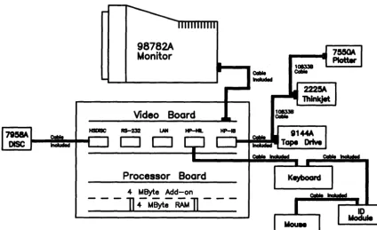
Typical system diagrams are shown in Figures 1-1 and 1-2.
Cable Included
98782A
Monitor
Video Boord
D O
Processor Boord
4
MByte
Add-on]4MByt;RA'M]
-Figure 1-1. Model 350 Typical Workstation
98782A 19 inch Monitor
2-Slot 010 Backplane
DOS Coprocessor Board Cable Included
108338
Coble
108338
Cable
98624A Interface 9144A
---L-,~~~=Wl Tape Drive
HP-18 RS-232 LAN HP-HIL
D O
Processor Board
Keyboard
[image:18.618.89.513.75.334.2]Video Board
Figure 1-2. Model 330 Typical Workstation
2 Product Information
[image:18.618.76.531.194.646.2]Features
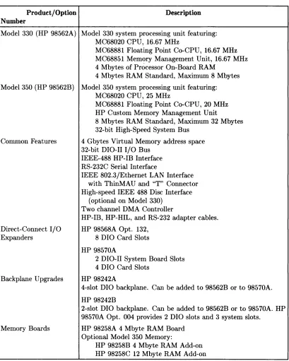
These cornputers have several useful features. Table 1-1 lists the main features.
Table 1-1. Model 330/350 Computer Features
Product / Option Description Number
Model 330 (HP 98562A) Model 330 system processing unit featuring: MC68020 CPU, 16.67 MHz
MC68881 Floating Point Co-CPU, 16.67 MHz MC68851 Memory Management Unit, 16.67 MHz 4 Mbytes of Processor On-Board RAM
4 Mbytes RAM Standard, Maximum 8 Mbytes
Model 350 (HP 98562B) Model 350 system processing unit featuring: MC68020 CPU, 25 MHz
M C68881 Floating Point Co-CPU, 20 MHz HP Custom Memory Management Unit
8 Mbytes RAM Standard, Maximum 32 Mbytes 32-bit High-Speed System Bus
Common Features 4 Gbytes Virtual Memory address space 32-bit DIO-II I/O Bus
IEEE-488 HP-IB Interface RS-232C Serial Interface
IEEE 802.3/Ethernet LAN Interface with ThinMAU and "T" Connector High-speed IEEE 488 Disc Interface
(optional on Model 330) Two channel DMA Controller
HP-IB, HP-HIL, and RS-232 adapter cables. Direct-Connect I/O HP 98568A Opt. 132,
Expanders 8 DIO Card Slots
HP 98570A
2 D I 0-II System Board Slots 4 DIO Card Slots
Backplane Upgrades HP 98242A
4-slot DIO backplane. Can be added to 98562B or to 98570A.
HP 98242B
2-slot DIO backplane. Can be added to 98562B or to 98570A. HP 98570A Opt. 004 provides 2 DIO slots and 3 system slots.
Memory Boards HP 98258A 4 Mbyte RAM Board Optional Model 350 Memory:
HP 98258B 4 Mbyte RAM Add-on HP 98258C 12 Mbyte RAM Add-on
[image:19.611.103.512.134.645.2]Performance
The Model 350 computer provides 3-5 MIPS computational performance and offer high-performance graphics display to match the CPU. They are typically used as group resource workstations (shared by several designers) and as group computational and shared peripheral resources when networked to lower performance workstations belonging to individual engineers.
These workstations must be able to run UNIX-based applications for:
• Advanced design tasks (ME, EE, and others)
• Expert Systems Development
• PC Board Routing
• Circuit Simulation
High-end workstations must be networked via industry-standard LAN, preferably have AT&T System V UNIX2 operating system compatibility, high-resolution monochrome or color displays, and very large RAM capacities.
Performance of Model 350 workstations is about four times that of a VAX 11/780* minicomputer doing integer computation. Now, applications once limited to large mainframes can be executed locally. New applications of artificial intelligence, coupled with design software, can now be developed and significantly increase the productivity of the design professional.
Full potential of the MC68020 processor is realized by the use of a 32 Kbyte cache with 32-bit wide entries operating at a 120 nsec cycle time (zero processor wait states). This large, high-performance cache buffers the 25 MHz processor from the main memory operating at an average 180 nsec cycle time over a 32-bit wide system bus. Hewlett-Packard's custom Memory Man-agement Unit (MMU) translates virtual memory addresses into physical memory addresses in parallel with cache-miss detection (HP-UX only). This means that maximum system throughput is maintained for very large programs and multiple processes.
* Workstation vendors use the VAX 11/780 performance as the yardstick for system CPU performance (MIPS). Using this yardstick makes the Model 350 a 4 MIPS system.
2 UNIX is a trademark of AT & T
Hardware
CPU - MC68020
Both models are an extension of the Series 300 family. Through use of the MC68020 at 16 MHZ (Model 330) and 25 MHz (Model 350), high-end performance of the Series 300 family is almost doubled and provides state-of-the-art technology.
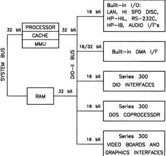
Bus Architecture
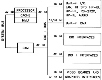
A 16-bit I/O bus provides interfacing to most Series 200 and 300 accessory cards. This bus is called the DIO bus.
To increase speed, a new 32-bit I/O bus is used in this computer for even higher performance. This bus is called the DIO-II bus and provides 6 Mbyte/sec transfer rates, handling even the highest-performance peripherals independently of processor access to main memory. It is com-patible with the 16-bit DIO bus of the Series 200 and the Model 310 and 320 computers, allowing access to most accessory and interface cards available for those systems.
Model 350 memory boards are accessed by a third, very-high speed :32-bit system bus. Con-necting between the processor board and RAM boards, it allows faster read and write cycles than the I/O busses would permit.
Figure 1-8 is a diagram of the I/O architecture for the Model 330 and 350 computers.
16 bit Built-in I/O:
LAN. HI SPD HP-IB.
32 bit PROCESSOR 32 bit HP-HIL. RS-232C.
CACHE HP-IB. AUDIO
MMU 16/32 bit
(/) Built-in DMA
:::::>
m
T
0 16 bit 010 INTERFACES
C
32 bit
RAM
32 bit 010 II INTERFACES
16 bit VIDEO BOARDS AND or 32 bit GRAPHICS INTERFACES
Figure 1-3. Model 330/350 Computer I/O Architecture
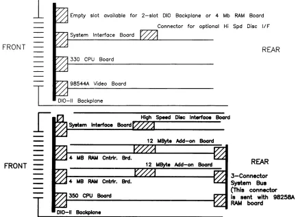
[image:21.611.132.479.386.659.2]Motherboard/Backplane
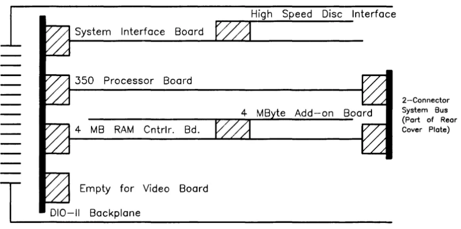
As Figure 1-4 shows, three motherboard system-slot connectors are used by the system processor board, system interface board, and RAM board. One system slot is available for the video board, display system interface board, or 2-slot DIO backplane.
System Interface Board
350 Processor Board
4 MB RAM Cntrlr. Bd.
T
Empty for Video Board 010-11 BackplaneFRONT
High Speed Disc Interface
2-Connector
System Bus
(Port of Rear Cover Plate)
[image:22.614.82.535.125.350.2]REAR
Figure 1-4. Model 350 System Slot Diagram
Keyboards
Two keyboards are compatible with the Model 330 and 350 HP-HIL interface:
HP 46021A
Standard keyboard is the Integrated Terminal Format (ITF) Keyboard. It connects to the HP-HIL connector on the system interface board.
IriP 98203C
An optional keyboard with the same keys and rotary control knob as used with several Series 200 and 300 COITlputers. It is used on the HP-HIL interface.
HP 9000 Hardware Compatibility
lModel 330 and 350 hardware compatibility ensures use and/or support of the same:
• Series 200/300 interface/accessory cards (except 256 Kbyte and 1 Mbyte RAM cards). • Series 300 graphics subsystems
• Peripherals supported on other Series 300 systems.
These workstations are fully compatible with the wide range of disc and tape drives, printers and plotters, and HP-HIL devices.
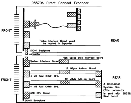
Either of the two optional Direct-Connect I/O Expanders can be added to the Model 330 or :350, allowing system expansion as application needs increase.
FRONT
FRONT
1
1
I
T
98570A
Direct Connect I/O Expander
Two System Slots
350
Four System Slots
010-11 Backplane
SPU
4-Slot 010 Backplane
Option 004 deletes this backplane leaving four total system slots
REAR
98568A with Option
132
1
1
I
T
Direct Connect I/O Expander
8-Slot 010 Backplane
REAR
010-11 Backplane
Figure 1-5. Direct Connect Expanders Diagram
Operating Systems
HP-UX 5.2
Series 300 HP-UX 5.2 adds support for both computers while maintaining object code compat-ibility with earlier releases. Programs will continue to run without recompiling. The 5.2 release supercedes all previous Series 300 releases.
Additional comlnands have been added so that the computer has a command set identical to the Model 840. All commands that are not hardware, dependent are on the Series 300 systems, except job control.
The AppHcation Execution Environment (AXE) is now available in both a single-user version and a new multi-user version. Single-user limitations have been removed. No additional com-mands or utilities are included. It is intended for use with run-only multi-user applications. Additional administration may be necessary for a multi-user system. The multi-user Program-ming Environment now requires the multi-user AXE as a prerequisite.
All of these computer's HP-UX systems feature a built-in LAN, allowing them to function as departmental resource servers for sharing space on large local discs and for sharing attached high-quality printers and plotters. Because the LAN is an industry standard, the Model 350 workstations can also be connected to other vendors' systems to access data and to utilize the other computing resources available to the department.
BASIC 5.0
BASIC 5.0 (HP 98613C) is a revision of the Series 200/300 BASIC 4.0, Revision 4.03. BASIC 5.0 provides upward compatibility with BASIC :3.0 and 4.0. New for BASIC 5.0 is a Hierarchical File Systelm (HFS) Binary. Model 350 users now have access to the HP-UX file system directory, with or without HP- UX. HFS is compatible with LIF and SRM and provides easy switching between BASIC and HP-UX via soft re-boot.
BASIC 5.0 is sold either as a standalone language system or bundled with Series 200/300 systems, including the Model 330 or 350.
Pascal 3.2
Pascal 3.2 provides selective file back-up and is object code compatible with Pascal 3.1. An
HFS Binary also provides access to the HP-UX file system directory with or without HP-UX.
Software Compatibility
For software, these computers:• Use the same Series 300 Application Software Object Code . • Are source code compatible with HP Precision Architecture.
Product Identification
Several terms in this manual are used to describe and identify the various parts of the computer and bus expander. This section explains the terms used to improve your understanding of service information.
Product Identification Terms
Each product has its set of included hardware similar to that in Table 1-1. Product numbering conventions used with this cOInputer are explained here to clarify the following information:
• Systems Ordered by Customers.
• Products Ordered by HP Field Offices.
• Products Manufactured by HP Ft. Collins Systems Division
Systems Ordered by Customers.
When these computer systems are ordered by customers, a suffix is added to the Model number, such as Model 350AIM that identifies the computer system ordered by customers. Refer to the Model 350 Hardware Price List for a current listing of all bundled systems.
Products Ordered by HP Field Offices.
A five-digit product number is used by HP field offices to order the computers. This number is strictly for ordering purposes and not for formal product identification. HP 9000 Series 300 Model 330 and 350 Computer is Product Number HP 98562A and 98562B, respectively. A complete explanation of these names and numbers is shown later in this chapter. Configuration and other product information is also covered.
Products Manufactured by HP Technical Workstations Operations
At the manufacturing division, the computer's are built and configured using the numbering conventions explained above. Note that these numbers relate only to the computer or bus ex-pander and do not include peripherals, such as disc drives, some monitors, and some accessories. Other HP divisions provide the rest of the products bundled with the computer system.
Serial Numbers
Serial nurnbers are affixed to each computer and bus expander for identification purposes. A decal on each product has the serial number. An example serial number is explained below:
Serial No. 2623A01234
10
Product Information
Location: Behind the power supply access cover on the inside bottom of the chassis.
Description:
5-digit unique identifying number.
Country of Origin Code.
Product Code, decoded as:
First 2 digits
+
60 = Last 2 digits of yearproduct was introduced or significantly changed. Last 2 digits = number of week in year product
Hardware Terminology
Hardware is used to define physical elements of these products. Different parts and locations of hardware items are explained below.
Product Terms/Conventions
The following terms are used to describe products and their main parts and areas:
• Computer - A product containing the central processing unit (CPU) and other assemblies such as RAM, interface, and video boards, and other accessory cards. Sometimes the computer is referred to as the System Processing Unit (SPU).
• DIO Slots - The narrow slots for accessories in the back of the computer or expander.
Two or four slots are available as options for the computer and expander. Distinction between these slots are:
• The top slot is an accessory card slot.
• The second slot down is an I/O card slot.
• System Slots - The wide slots in the computer or expander are for the processor, RAM, video, or system interface boards.
• Internal (circuit) - A circuit, such as an interface, that is part of the processor board. Internal does not mean 'inside the computer's case parts'.
• External (circuit) - A circuit that is located on an assembly other than the processor board. External does not mean 'outside the computer's case parts'.
• Peripheral - A device external to the computer, such as a keyboard, monitor, disc drive, plotter, printer, bus expander, etc.
• I/O :Expander - A device external to the computer that connects to the computer's DIO-II bus. This device provides power to its installed accessory cards and pernlits more of these cards to be used in the computer system. Sometimes they are called bus extenders. For the Model :350 computer systems, the product name is Direct-Connect System Slot I/O Expander.
• System - One or more computers with one or more peripherals connected together to run an application for a desired end result.
PC Boards
PC boards in the computer and bus expander are made of several component parts. Identifying terms used in this manual are:
• Cards - Boards installed in the DIO card cage slots.
• I/O Card - A card that outputs to and inputs from a peripheral device. They are installed in DIO slots. For example, an RS-232 I/O card.
• Accessory Card - A card that only operates on the DIO bus and does not talk. to a peripheral device. They are installed in either I/O or accessory card slots.
• Boards - Assemblies installed in the wide system slots or inside the product. Boards are not usually removed or installed by users.
Two-board assemblies are those consisting of one board connecting to the motherboard and an "add-on" board attached to the bottom board. 8 and 16 Mbyte two-board assem-blies are examples.
• Backplane - The board in the card cage with connectors for DIO cards to plug into.
Software Terminology
As used in this manual, software refers to information stored in, or on a device. Typically, this information can be changed and can be transferred to another location in the computer system. Types of software are:
• Firmware - The data or instructions in Read-Only-Memory (ROM) chips.
• Operating Systems - Computer languages, such as BASIC, Pascal, and HP-UX. They have various commands, statements, and keywords that when executed by the CPU in a particular sequence, cause computer to manipulate data to some desired end result.
• Application Program -A series of operating system program lines in a specific sequence to cause specific actions, such as accounting, electro-mechanical design, data sampling and output, etc. This information is sometimes referred to as software as it is information that is stored in or on a medium and can be transferred.
Hardware Support Documentation
The purpose of these computers and expanders Hardware Documentation is to support the installation and maintenance of these products. Hardware Support Docu-mentation consists of six manuals for the HP 9000 Series 300 Models 330 and 350 Computers and HP 98568A Opt. 132 and HP 98570A Expanders:
• Service Information Manual
• Service Handbook
• Service Notes
• Test Tools Manual
• Self-Paced Hardware Training Guide.
• HP 9000 Series 200/300/500 Site Preparation Manual
• Series 300 Computer Systenl Configuration Reference
The following manuals also relate to hardware:
• Various Installation Notes
• Series 300 Installation Reference
• Series 200/300 Peripheral Installation Guide
A complete listing of titles and part numbers is in Chapter 7 of this manual and the Model 330/350 Service Handbook, Chapter 10.
Service Information Manual
This manual (the one you're reading now) contains tutorial information on the computer's and bus expander's main features, functional descriptions of each assembly, and how to replace these assemblies.
Its purpose is to serve as a learning tool in training environments wherein the service person learns how the computer and bus expander works and its parts are replaced. Most of the information in the Service Information Manual is not found in the Service Handbook.
Organization of the Service Information Manual is as follows:
Chapter No. and Title Front Matter
Chapter 1: Product Information
Chapter 2: Assembly Replacement
Chapter 3: Functional Description
Chapter 4: Boot Rorvr Functions
Chapter 5: Troubleshooting
Chapter 6: Parts Lists
Chapter 7: Reference
Contents
Has legal notices, safety situations explained, plus a Ser-vice Information Locator to help you find serSer-vice infor-mation.
Introduces the computer/bus expander, covers features, specifications, options, accessories, operating systems, repair philosophy, and a general description of the Model 350 Computers and HP 98570 Bus Expanders. Has an overview of how the Hardware Documentation is orga-nized.
In this chapter, disassembly and reassembly of all field replaceable parts for the computer and bus expander are covered. Reference to the Service Handbook and Chapter 6 is made for part number information.
Each assemblies functional description is covered to block diagram level.
The sequence of events for power-up, self-tests, and booting an operating system are explained. Turn-on displays are shown.
This chapter contains tutorial infonnation for trou-bleshooting the computer and bus expander. Self-test errors for the computer and expander are explained. Has parts ordering information, as well as part numbers and descriptions of field replaceable parts.
Contains hardware/software manual titles, and other helpful information.
Service Handbook
This manual is intended to be used on site during service situations. It contains information useful to configuring, troubleshooting, and replacing parts. It is organized as follows:
Chapter No. and Title Contents
Chapter 1, Product Information Has a Has a brief description of the product, along with config-brief description of the product, uration and similar information. Product specifications
are also listed.
Chapter 2, Environmental, Installation, and PM
Chapter 3, Configuration
Chapter 4, Troubleshooting
Chapter 5, Tests
Chapter 6, Adjustments
Chapter 7, Systems
Chapter 8, Replacement Parts
Chapter 9, Diagrams
Chapter 10, Reference
Chapter 11, Service Notes
14 Product Information
Gives power requirements, fuse and power cord data, and installation information. If preventive maintenance is required, it is shown in this chapter.
Lists various product configurations and explains what each one is.
Lists tools required, including Test Tools, and explains several troubleshooting procedures. Flow charts are fre-quently used.
Lists tests to run to check out the computer, some pe-ripherals, and some accessories and interfaces.
There's no adjustments for the computer.
Refers to the Model 330/350 Pricing Information and Technical Data sheet for current bundled system con-figurations.
Lists part numbers for all field-replaceable parts and e1 plains how they may be obtained.
Block diagrams of the products are shown here.
Other documentation related to these products are listed here with their part numbers.
Test Tools Manual
Series 200/300 Test Tools Manual supports a software package for verifying the integrity of ~v1odel 330/350 computer system installations. The Test Tools manual and its associated discs or tape permit troubleshooting computer systems in failure analysis. Part numbers for the complete Test Tools packages are:
• 09800-12300 for 3.5-inch disk drives .
• 09800-12700 for 5.25-inch disk drives.
Contents of the four parts of the Test Tools Manual are
Part No. and Title Contents
Part I, Introduction and Built-In Tests Introduces the Test Tools package and overviews the computer self-tests and explains what the different tests do.
Part II, Computer Tests
Part III, System Functional Tests
Part IV, CS/80 Exercisers
Service Notes
Covers loading and running of Series 200 and 300 Com-puter Tests. Each test is explained as to what it does. Error messages are listed and explained.
Tells how various computer-peripheral tests are loaded and run. Tests are explained, error messages shown and defined. Examples of some tests are given. Includes tests for HP-HIL devices.
Explains how tests for CS/80 disc drives are loaded, ran, and results are interpreted. Error messages are shown as well as several examples of running the tests.
'iVhen a situation occurs that effects servicing of the computer or bus expander that is not covered in existing documentation, a Service Note is written to explain it. Service Notes are distributed through a Subscription Service to HP Customer Engineers and to customers on the Cooperative Support Program for these products. Being half-page in size, they are intended to be placed in Chapter 11 of the Model 350 Service Handbook.
Installation Notes
Each separately available accessory or upgrade has an Installation Note packaged with it. These Notes have instructions for configuring and installing the hardware.
Series 300 Configuration Reference Manual
All supported configurations of Series 300 Computer Systems are explained in this manual.
Section No. and Title
Section 1. Configuration Overview
Section 2. Operating Systems and Application Software
Section 3. System Packaging
Contents
Has configuration worksheets to assist in planning the application.
Covers supported languages and media options.
Lists the Model 350 features and options available.
Section 4. Interface and Peripheral Se- Explains Interfacing, networking, mass storage,
mOlll-lection tors, printers, and other output peripherals.
Section 5. Support Services Overviews Customer Training, installation and support services, and consulting.
Appendix A. Detailed Product Refer- Gives detail information about computers, accessones,
ence and peripherals.
Site Preparation Manual
Explains site preparation and how to prepare the computer site for hardware installation. Covers physical, environmental and electrical requirements. Its organization is shown below.
Chapter No. and Title
Chapter 1, Introduction
Chapter 2, Responsibilities
Chapter 3, Preparing the Electrical Environment
Chapter 4, Preparing the Physical Environment
Chapter 5, Providing Other Necessities
Chapter 6, Equipment Arrangement and Space Planning
16
Product InformationContents
Explains the purpose and contents of the Site Prepara-tion Manual.
Identifies customer and HP responsibilities for preparing the HP 9000 Computer Systenl site. Includes a time frame for setting up the computer system, and identifies people who can provide assistance.
Includes power specifications, dealing with electrical in-terference, connecting cables, and data communication configurations.
Explains heat and humidity considerations, airborne contaminants, and shipping weights and dimensions for movement and storage.
Covers media storage, equipment and record protection, computer supplies, and nearby telephones for assistance which are an integral part of preparing for and sustain-ing the operation of a computer system.
Chapter 7, When Your Computer Arrives
Appendix A
Appendix B
Discusses the final preparation for system arrival, coor-dinated deliverie.s, arrival dates, how to check for dam-age in shipment, unpacking the cartons, and scheduling the installation of HP 9000 Computer Systems.
Lists product specifications for electrical requirements, heat generation, temperature and humidity require-ments, and shipping dimensions.
Contains forms to use for preparing the site, such as Pre-Installation Worksheet, Shipment Scheduling Form, and a Site Completion Checklist.
Installation Reference
The computer and expander each have step-by-step procedures for installing them. An Instal-lation Card is a pictorial set of instructions to show the installer how to unpack, connect, and power up the cornputer, disc drive, and monitor. More detailed information is contained in the Installation Reference. To install the operating system and/or application program, the documents supplied with these software products should be referred to.
Organization of the Installation Reference is:
Chapter No. and Title
Chapter 1 : Introduction
Contents
Covers how the guide is organized and explains some computer fundamentals.
Chapter 2: Installing Your Computer Includes procedures on positioning the computer, check-ing voltage settcheck-ings, connectcheck-ing power cords, and turn-ing on the computer.
Chapter 3: Installing Accessories This chapter covers accessory configuration and instal-lation, such as memory or interface cards.
Chapter 4: Installing Your Keyboard This chapter covers keyboard and monitor installation. and Monitor
Chapter 5: Installing HP-IB Peripherals
Chapter 6: Installing Non-HP-IB Peripherals
Chapter 7: Reading the Self-Test
Reference
Glossary
18
Product InformationStandard HP-IB peripheral configuration and connec-tion procedures.
Peripheral configuration and connection procedures other than HP-IB.
Covers procedures performed by self-test and how to interpret the results of the self-tests. Error messages are explained and help is provided should the user get into trouble at this point.
This chapter has information regarding internal config-uration switches, running extended tests, Boot ROM error messages and tutorial information on data com-munications and interfacing.
Specifications
Electrical
Line voltage/Frequency
Fuse
Backplane Power Available Model 330/350 Computer, HP 98568A Opt. 132 Expander, and HP 98570A Expander
Line transient spike immunity (1 nsec rise, 800 nsec duration) Power Consumption Current Requirements
Maximum Heat Dissipation
Battery Back-up
Environmental
Operating temperature Operating humidity Operating altitude
120 Vac @ 48-66 Hz
240 Vac @ 48-66 Hz
8AF 250V
Total Power Available from motherboard: 95 Watts @ +5 V dc
40 Watts @ +12 Vdc
12 Watts @ -12 Vdc
Each system slot: 23 Watts @ +5 V dc
10 Watts @ +12 Vdc
3 Watts @ -12 Vdc
1 KVdc
250 Watts maximum 5.0 A @ 120 Vac
3.0 A @ 240 Vac
853 BTU/hr 250 Kcal/hr
Real-Time Clock on System Interface Board
0- 55° C 5 - 95% relative
4572 metres (15000 feet)
Electromagnetic Interference
Standards met
Regulatory Requirements
Standards met
Physical
Dimensions
(Computer or Expander) Height
Width Length Weight
Vibration Standard
Shipping Information
FCC Class A VCCI Class 2
VDE Class B, VDE 1046/84
UL 478, 5th Edition CSA 154M-1983
IEC 380, 3rd Edition; 435, 2nd Edition
130 mm (5.12 inches) 325 mm (12.8 inches) 376 mm (14.8 inches)
11.8 kg (26 pounds) maximunl Meets Class B requirements
The shipping container for each computer includes the Localization Kit, which includes power cords, fuse, keyboard cable, HP-HIL cable, Installation Reference, and Installation Picture Card.
Models 330 or 350 Computer
Shipping Weight Container Dimensions
15.9 kg (35 pounds)
Width - 502 mm (19.75 inches) Length - 559 mm (22 inches) Depth - 267 mm (10.5 inches Cube - 0.07 m3 (2.65 feet3)
HP 98568A Opt. 132 or 98570A Expander
Shipping Weight Container Dimensions
20
Product Information12 kg (26.4 pounds)
Model 350 Processor Board
CPU
Floating Point Co-Processor lV1emory ~1anagement::
Type
Virtual Memory Contexts
Page size Cache Memory
Type
RAM Cycle time Partitioning Timers
Match interrupt Delay interrupt Cyclical interrupt System TinIer Beeper
Frequency range Resolution Duration
MC68020 at 25 MHz MC68881 at 20 MHz
HP Custom MMU 4 Gbytes per process 84 default, user settable 4 Kbytes / page
Write through, instruction, data (external to MC68020 instruction cache)
16 Kbytes, 8K words of 32-bit entries 120 nsec
Four 32-bit words each; 2K partitions
Match on time of day 0.00 - 86400.00 seconds 10 msec - 1.94 days
10 msec - 1.94 days
4J.lsec resolution, accurate to 25 ppm
Three independent tone generators controllable over 30 db.
81.46 Hz - 8.33 KHz
Capable of approximate tone scale over 5 octaves 0.01 sec to 2.55 sec per tone
Model 330 Processor Board
CPU Type
Clock Frequency
Internal Architecture
Address range
Data bus
Co-processors
Floating point Type
Clock Frequency
MMU Type
Clock Frequency
On-Board memory
Size
Type
A verage cycle time
Memory
Memory Boards
Type
System bus width
Bandwidth
A verage cycle time
Memory Sizes
Model 330 Standard RAM
Model 330 Maximum RAM
Model 350 Standard RAM
Model 350 Maximum RAM
22
Product InformationMotorola MC68020 16.67 Mhz
32-bit data and address registers
4 Gbytes virtual mapped to 4 Gbytes physical
32-bit synchronous to:
4 Mbytes On-board RAM
Motorola M C68881 16.67 Mhz
Motorola MC68851 16.67 Mhz
4 Mbytes
Byte parity error-checking 300 nsec
Byte parity error-checking
32 bits address; 32 bits data
22.2 Mbyte/sec read; 14.3 Mbyte/sec write 180 nsec
4 Mbytes on processor board
8 Mbytes (4 Mbytes on processor plus one 4 Mbyte RAM controller board)
8 Mbytes: 4 Mbyte controller board plus 4 Mbyte add-on board
010-11 I/O Bus
Width
Bus bandwidth
System Interface Board
LAN Interface Media Protocols Data Rate Disc Interface
Type Data Rate
N umber of connected drives
Parallel Interface Type
Data Rate
N umber of connected devices Serial Interface
Type Connector
Battery-backed Real-Time Clock Resolution
Accuracy Battery type Keyboard requirements
32 bits address; 32 bits data 6 Mb/sec
ThinLAN coax cable (RG 58U) IEEE 802.3, Ethernet
10 Mbits / sec
IEEE 488 1 Mbyte/sec
8 per interface supported
(Additional disc interfaces are available as optional ac-cessories)
IEEE 488 350 Kbyte/sec
15 per interface devices supported
RS-232C standard
DB9 with cable; adapter to DB25
10 milliseconds ±5 seconds/day
Lithium; 1 year expected life
HP 46021A (ITF type) with HP-HIL interface, 107-key low profile with numeric keypad, 8 special-function keys HP 98203C with HP-HIL interface, 106-key with rotary control knob, including 10 special-function keys.
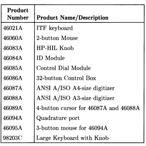
HP-HIL and Video Accessories
Listed below are HP-HIL and video accessories compatible with the Model 350 workstations. For a complete list, consult the lIP 9000 Series 300 Model 350 Hardware Price List, Part Number 5954-7061D.
Table 1-2. HP-HIL Devices
Product
Number Product Name/Description
46021A ITF keyboard
46060A 2-button Mouse
46083A HP-HIL Knob
46084A ID Module
46085A Control Dial Module
46086A 32-button Control Box
46087A ANSI A/ISO A4-size digitizer
46088A ANSI A/ISO A3-size digitizer
46089A 4-button cursor for 46087 A and 46088A
46094A Quadrature port
46095A 3-button mouse for 46094A
98203C Large Keyboard with Knob
Table 1-3. Video Accessories
Product
Bus and Type Number Product Name/Description
DIO Video Card HP 98546A Display Compatibility Interface
DIO-II System Boards HP 98287A HP 98700A Interface
HP 98542A Medium Resolution Monochrome Video Board
HP 98543A Medium Resolution Color Video Board HP 98544B High Resolution Monochrome Video Board
HP 98547A 6-plane High-performance Color Video Board
[image:40.611.186.428.144.385.2]Hewlett-Packard Support
Support services and policies mentioned in this section are subject to change. Please consult your local Hewlett-Paekard Sales and Service Office for the current support policies.
Repair Philosophy
Field Repair Philosophy for the Model 330/350 Computers and the HP 98568A Opt. 132 and H8570A Expander is assembly, or board level. This means that when a failure occurs, the problem is diagnosed to the assembly having the failed part. That assembly is then replaced. Replaeement assemblies are available through local HP Sales and Service Offices.
Some assemblies may be exchanged for rebuilt ones. Other assemblies are only available as new ones. Refer to Chapter 6, or the Serviee Handbook, Chapter 8, for information on replacement parts.
Schematics
In support of the repair philosophy, this manual contains information to the assembly level. Schematics are not available for these products.
Supported Configurations
Only computer systems with Hewlett-Packard approved parts, accessories, peripherals, operat-ing systems and application programs are supported by Hewlett-Packard. Any computer system with other than HP approved hardware or software connected or installed must have the non-HP approved hardware and software removed by the customer before On-Site or Serviee Center repair is accomplished.
Repair Services
Hewlett-Packard provides repair services in three ways: • On-Site Repair.
• Service Center Repair. • Customer Repair.
On-Site Repair
For On-Site Repair, an HP Customer Engineer goes to the customers site, troubleshoots, and repairs the hardware to the assembly level. The defective assembly is replaced with a new or rebuilt assenlbly. This service is available through a service contract or a time-and-materials basis.
Hewlett-Packard Service Center Repair
The custOlner returns the defective product to the nearest HP Repair Center. An HP Customer l8ngineer repairs the product to the assembly level in the same manner as On-Site Repair. Upon being repaired, the product is returned to the customer. Contact your nearest HP Sales and Service Offiee for the location of the HP Repair Center, typical turn-around times, and shipping instructions.
Customer Repair
Customers have the option of repairing their own HP computer products. Contact your nearest
HP Sales and Service Office for information concerning service training, special tools and test equipment, and spare parts.
Hewlett-Packard offers a Customer Cooperative Support Program to assist customers in main-taining their HP computer products. A variety of technical services and information are avail-able. Your local HP Sales and Service can provide you with information about the Cooperative Support Program.
Hardware Support Services
There are many hardware support options available, from utilizing on-site maintenance groups to buying full support from the local sales offi<;e. Please contact your local Hewlett-Packard Sales and Service Office for these services.
Operating Systems Support
Primary Support
There are numerous operating system support options:
• Account Management Support (AMS) provides a local SE, on-site assistance, one Re-sponse Center caller and one alternate for telephone assistance, and a Software Materials Subscription.
• Response Center Support (RCS) provides one Response Center caller and one alternate for telephone assistance, and Software Materials Subscription.
• Software Materials Subscription (SMS) provides software and manual updates, Software Status Bulletins, and HP communicator magazine. Updates to ROM-based systems are not provided.
Support For An Additional System
The following options support an additional system:
• Additional System Coverage extends AMS or RCS coverage on the operating system to one additional system under the same system manager. All support is delivered through the central system.
• Extended Materials Support extends SMS by providing the right to make one copy of all central system materials for use on one additional system.
• Additional Response Center Caller provides one additional caller and one alternate for access to the HP Response Center
• Manual Update Service (MUS) provides one copy of updates to software reference man-uals.
• Software Notification Service (SNS) provides issues of the HP Communicator and Software Status Bulletin.
Assembly Replacement
2
lintroduction
Replacing parts in either the computer and expander require almost identical procedures. With the exception of a few parts unique to each unit, the access and replacement procedures are the same.
VVhen the process is the same for both the computer and expander, they are referred to as the "unit". If different procedures are used for the computer or expander, the name of the unit is used.
Tools Required
CAUTION
The computer and bus expander use metric screws requiring the use of Pozidriv® screwdrivers. Do not use other cross-tip screwdrivers, such as Phillips or Reed-Prince. They will eventually damage the Pozidriv® screw head recess making screws hard to remove.
All field replaceable parts can be accessed with these tools:
• Static-free Workstation, HP Part Number 9300-0794
• #1 Pozidriv® screwdriver, 4-inch (100 mm) blade.
Used for all screws except the power supply ground tab screw and expander to computer attaching screws.
• #2 Pozidriv® screwdriver, 4-inch (100 mm) blade.
Used for the power supply ground tab screw and expander to computer attaching screws.
• Flat-tip screwdriver, 0.125-inch (3 mm) wide tip, 4-inch (100 mm) blade.
• Anti··Static Bags
Access Flow Chart
Figure 2-1 is an Assembly Access Flow Chart showing the access process to replace parts. To use this chart, identify the part to be replaced at the bottom of the chart. Then start at the top of the chart and work through the blocked steps toward the part to replace. This flow chart can also be used as a guide to install assemblies by starting at the bottom and working toward the top.
If you are learning how to replace parts in the computer and bus expander, you may want to start at the left side of the flow chart and remove each part in sequence. Procedures in this chapter are also organized in the same manner. Referencing the Model 330/350 Service Handbook, Chapter 8, Replaceable Parts, as you remove each assembly/part for the first time
will help associate the part numbers with their respective assemblies
~
00
&g