© 2017, IRJET | Impact Factor value: 5.181 | ISO 9001:2008 Certified Journal | Page 3612
Experimental Study using Earthquake Shake Table
A. P. Kulkarni
1, M. K. Sawant
2, M. S. Shindepatil
31,2,3
Assistant professor, D. Y. Patil Institute of Engineering, Management & Research, Akurdi, Pune: 411044
---***---Abstract -
In this paper the stability of a three storeybuilding is studied for various conditions under two different scenarios, with and without the use of base isolation technique in the form of dampers. As shake table are used in many research work as it produces the same effects that earthquake produces. Using horizontal shake table analysis of deflection of building is done for different cases. Designing of shake table is done considering the factors and specifications of earthquake produced. Type of Payload is set according to the building characteristics and frequency is to be set according to the earthquake produced various uses and advantages of shake table are also studied during our analysis work. Also different types of base isolation materials are mentioned. By using springs as a base isolating material analysis is done.
Key Words: Earthquake, Dampers, Shake table, Payload
1.
INTRODUCTION
When tectonic plates are in motion. Plates collide with each other and due to so vibration is developed. The point within the earth where earthquake rupture starts is called focus or hypocenter. The point on the earth’s surface vertically above the focus of the earthquake is called epicenter. Earthquake is more intense at the places of epicenter. The depth of the focus from the epicenter is called focal depth. Smaller size of earthquake takes place before and after a big earthquake. Those occurring before are called foreshocks and those occurring after are called aftershocks.
Earthquakes are part of this environment. Apart from destruction of life and property, they can have serious indirect consequences. The exact simulation of earthquake motion has been a serious challenge to researchers and engineers. Shake table testing is being increasingly used in earthquake engineering research centre worldwide, as it is the only available means of nearly truly reproducing the dynamic effects that earthquakes impose on structures. Large energy released energy released during earthquake travels as seismic waves in all directions through earth layers. Primary waves are the fastest waves and can travel through all the materials like solid, liquid or air. They are longitudinal in character. Secondary waves are transverse waves. They can travel through solids, but not in liquids. These waves are slower than p-waves Rayleigh waves are produced by interaction of P and S waves with earth. These waves are involved in horizontal & vertical motion of earth
Love waves are faster than Rayleigh waves but cannot pass through water. They do not have vertical component of velocity.
1.1 Shake Table
Shake table are an essential tool for assessing the behavior of structural components, the whole system works similar to those induced in real earthquake. Shake table are used to study the dynamic effects on the performance of specimens. There are two shaking tables in the world which are large enough to test the full – scale structures, one jumbo shaking table in JAPAN and the one in USA.
1.1.1 Horizontal Shake Table
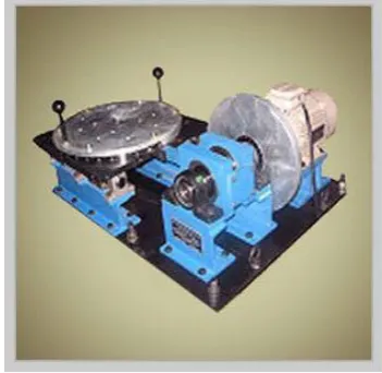
[image:1.595.345.521.523.694.2]In horizontal shake table the cam is connected to a variable speed motor with the help of a shaft and a fly wheel. A circular mounting plate is placed on a vibrating plate so that the test structure can be mounted at any desirable angle. The table is able to generate harmonic motions of different amplitude. Horizontal shake table will produce horizontal base motions. The amplitude of base motion can varied by changing the eccentricity of the cam. By varying the speed of motor, the frequency content of the base motion can be varied.
Fig -1 Horizontal shake table
1.1.2
Vertical Shake Table
© 2017, IRJET | Impact Factor value: 5.181 | ISO 9001:2008 Certified Journal | Page 3613 vibration table and a cam. The cam will be connecting to a
variable speed motor with the help of bearing assembly. The vibration table will be mounted on springs and the roller supports prevent wobbling. Frequency control 5% accuracy . A screw mechanism will be presents to vary the amplitude of base motion. By varying the speed of motor, the frequency content of the base motion can be varied.
1.1.3
Servo Electric Shake Table
[image:2.595.47.273.290.400.2]Servo electric shake table will consist of a Servo Actuator is controlled through computer. Various base motions such a sine, square, random, etc. will be given to Actuator and accordingly the top table will vibrate. A circular mounting plate will be placed on the vibrating plate.
Fig -2 Servo Electric Shake Table
1.1.4
Servo Hydraulic Shake Table
Servo hydraulic shake table is a closer look control based actuation mechanism. Servo based direction control valve is the heart of the entire system.
[image:2.595.337.522.496.753.2]Servo valve basically governs the flow and pressure of the oil to the Actuator. Accordingly the Actuator moves forward and backward and hence the shake table The Actuator has a Position Feedback Sensor (PFS) which sand the signal of the motion controller. Controller verifies the position and if there is any difference with respect to initially fade Valve and corrects it by moving the Actuator front or back.
Fig -3 Servo Hydraulic Shake Table
1.2. Uses Of Shake Table
1. To check the stability of Building models 2. To check the stability of Bridge models
3. Components of building and bridge such as beam and column and foundation.
4. Assessment of dynamic and seismic behavior of civil engineering structures
1.3. Advantages of Shake Table
1. As it tests the resistance of structures in earthquake which becomes helpful from destructions.
2. Dynamic structural behavior can be done which helps to understand the situations of the structures. 3. Various types of ground vibrations and seismic
research can be done by using shake table.
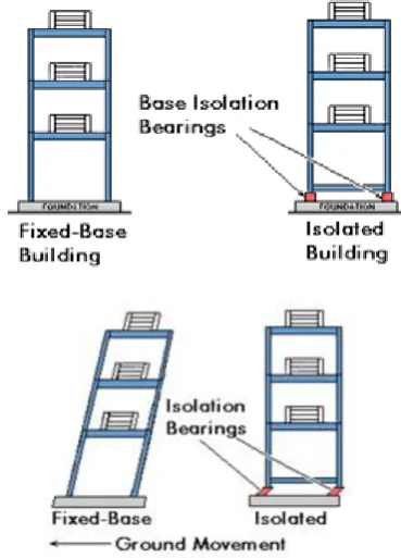
1.4. Base isolation
Base isolation is a technique of controlling structural response in which the building or structure is decoupled from the horizontal components of the earthquake ground motion by interposing a layer with low horizontal stiffness between the structure and its foundation. The concept of base isolation is explained through an example of building resting on frictionless rollers when the ground shakes the rollers freely roll, but the building above does not moves. Thus no forces is transmitted to the building due to shaking of ground, simply the building does not experience the earthquake. Now if the same building is rested on flexible pads that offers resistance against lateral movements then some effect of the ground shaking will be transferred to the building above, if the flexible pads are properly chosen the forces induced by ground shaking can be few times smaller than experienced by the building built directly on ground namely a fixed base building.
[image:2.595.53.266.568.677.2]© 2017, IRJET | Impact Factor value: 5.181 | ISO 9001:2008 Certified Journal | Page 3614
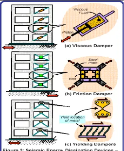
1.4. Seismic Dampers
Another approach for controlling seismic damage in buildings and improving their seismic performance is by installing seismic dampers in place of structural elements such as diagonal braces. These dampers act like the hydraulic shock absorbers in cars-much of the sudden jerks are absorbed in the hydraulic fluids and only little is transmitted above to the chassis of the car. When seismic energy is transmitted through them, Dampers absorb part of it, and thus damp the motion of the building.
[image:3.595.37.293.424.736.2]Energy dissipation by dampers helps in overall reduction in displacement of the structure. This technique is most effective in structures that are relatively flexible and have some inelastic deformation capacity. This approach to, is technically complex, but less costly then base isolation. The energy dissipating devices are dampers which transform earthquake energy into heat which is dissipated into the structure. These may be provided in isolation or coupled which rubber pads in series or parallel. A wide range of energy dissipation device has been developed and is now being installed in real buildings. Energy dissipation device are also often called damping device. the various types of dampers are described below.
Fig -4 Use of different types of dampers
2.
3.
LITERATURE REVIEW
S. J. Patil, G. R. Reddy [1] in 2001 developed state of art review base isolation system for structures. This paper presents an overview of the present state of base isolation techniques with special emphasis and a brief on other techniques developed world over for mitigating earthquake forces on the structures. The dynamic analysis procedure for isolated structures is briefly explained. The provisions of FEMA 450 for base isolated structures are highlighted. The effects of base isolation on structures located on soft soils and near active faults are given in brief. Simple case study on natural base isolation using naturally available soils is presented. Also, the future areas of research are indicated.
© 2017, IRJET | Impact Factor value: 5.181 | ISO 9001:2008 Certified Journal | Page 3615 James M. Kelly [3], Professor Emeritus Civil and
Environmental Engineering, University of California, Berkeley developed origin & development of base isolation techniques. In recent years base isolation has become an increasingly applied structural design technique for buildings and bridges in highly seismic areas. Many types of structures have been built using this approach, and many others are in the design phase or under construction. Most of the completed buildings and those under construction use rubber isolation bearings in some way in the isolation system. The ideas behind the concept of base isolation are quite simple. There are two basic types of isolation systems. The system that has been adopted most widely in recent years is typified by the use of elastomeric bearings, the elastomer made of either natural rubber or neoprene. In this approach, the building or structure is decoupled from the horizontal components of the earthquake ground motion by interposing a layer with low horizontal stiffness between the structure and the foundation. This layer gives the structure a fundamental frequency that is much lower than its fixed-base frequency and also much lower than the predominant frequencies of the ground motion. The first dynamic mode of the isolated structure involves deformation only in the isolation system, the structure above being to all intents and purposes rigid. The higher modes that will produce deformation in the structure are orthogonal to the first mode and consequently also to the ground motion. These higher modes do not participate in the motion, so that if there is high energy in the ground motion at these higher frequencies, this energy cannot be transmitted into the structure. The isolation system does not absorb the earthquake energy, but rather deflects it through the dynamics of the system. This type of isolation works when the system is linear and even when undamped; however, some damping is beneficial to suppress any possible resonance at the isolation frequency. The second basic type of isolation system is typified by the sliding system. This works by limiting the transfer of shear across the isolation interface. Many sliding systems have been proposed and some have been used. In China there are at least three buildings on sliding systems that use specially selected sand at the sliding interface. A type of isolation containing a lead-bronze plate sliding on stainless steel with an elastomeric bearing has been used for a nuclear power plant in South Africa. The friction-pendulum system is a sliding system using a special interfacial material sliding on stainless steel and has been used for several projects in the United States, both new and retrofit construction.
4.
SPECIFICATION, MECHANISM & KINEMATIC
ARRANGEMENT
4.1
Main Components of Shake Table
3.1.1 Motor
It commonly consists of two basic parts, an outside stationary stator having multiphase coils supplied with alternating current to produce a rotating magnetic field, and an inside rotor attached to the output shaft producing a second rotating magnetic field by at least the relative mechanical rotation of the output shaft. Pulling or pushing the poles of the two magnetic fields along, the stator and rotor rotating magnetic fields must maintain synchronism for average torque production. Asynchronously rotating magnetic fields would produce pulsating or non-average torque. The magnetic poles of the rotor magnetic field are produced by permanent magnets, reluctance saliency, or DC or AC electrical windings. AC/DC mechanically commutated machines in which speed is dependent on voltage and winding connection.
3.1.2 Gear Box
A machine consists of a power source and a power transmission system, which provides controlled application of the power. Merriam-Webster defines transmission as an assembly of parts including the speed-changing gears and the propeller shaft by which the power is transmitted from an engine to a live axle. Often transmission refers simply to the gearbox that uses gears and gear trains to provide speed and torque conversions from a rotating power source to another device.
3.1.3 Pulley and Shaft
A belt and pulley system is characterized by two or more pulleys in common to a belt. This allows for mechanical power, torque, and speed to be transmitted across axles. If the pulleys are of differing diameters, a mechanical advantage is realized. A belt drive is analogous to that of a chain drive, however a belt sheave may be smooth, so that the mechanical advantage is approximately given by the ratio of the pitch diameter of the sheaves only, not fixed exactly by the ratio of teeth as with gears.
3.1.4 Nuts And Bolts
Different types of nuts & bolts. Hexagonal bolt-nut pair is being used commonly. They are used for temporary joints.
3.1.5 Circular Plates
© 2017, IRJET | Impact Factor value: 5.181 | ISO 9001:2008 Certified Journal | Page 3616
3.2 Components We Used:-
Motor -
1400 RPM. Motor is used to vibrate the table.
Gear Box -
Gearbox is used to get various types of speeds of shake table.
Pulley
– Pulley is used to connect motor and gearbox and to increase and decrease speed. Shaft -
Shaft is used to connect the pulley. Shake Table -
It is the main part on which theloading rests.
Nut- Bolts -
Nut-Bolts are used to connect plates and rods.
Connecting Rod -
Connecting rod is used to connect circular plate and gearbox.
Circular Plate -
Circular plate is used to connect table and connecting rods.
Rollers-
Rollers are used to provide smoothness to table.
Supporting Table -
Supporting table is used to support whole system.3.2.1 Specifications
Motion :
Simple Harmonic
Type :
Motorized
Number of axis :
Single axis in horizontal
Frequency :
1-10 hertz
Frequency control :
+/- 2%[image:5.595.309.580.268.425.2]
Pay load :
5- 6 kgFig -5 Arrangements made for Analysis
5.
DESIGN OF SHAKE TABLE
4.1.1 Old Mechanism
Motor and gear box is connected with a step pulley of varying diameter with the help of shaft. Varying speeds can be developed with varying diameter of the pulley. Gearbox is connected with circular rods are connected with circular plate at input end and with shacking table at output end Connecting long rod = 300 mm
Connecting short rod = 80 mm
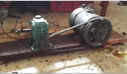
4.1.2 Modification In Old Mechanism
To set the requirement of getting proper functions of shake table various modifications are done. Due to frequency problems in shake table design various changes were done Firstly we used 0.25 HP motor, AC motor. But it was not able to bear the loads of shake table so we used 0.5 HP motor For increasing the frequency of the shake table diameter of the pulley of motor was kept large 190 mm & diameter of pulley of gear box was kept small 50 mm for getting required frequency.
Eccentricity of the circular plate was changed & kept nearer for getting the required deflection. We made these changes in the old mechanism for required functions of shake table.
Fig -6 Modified motor & gearbox arrangement
6.
DESIGN OF BUILDING
5.1. Components & Dimensions Of Building
a)
Column
i. Size of Column :- 25 x 25 mm
ii. Square column is being used. ( No of columns :- 18) iii. Height of column :- 230 mm
b)
Foundation Column
i. Square column ( No of columns :- 6) ii. Size of Column :- 25 x 25 mm iii. Height of column :- 100 mm
iv. Size of foundation block :- 70 x 85 mm v. Thickness of foundation block :-35 mm
c)
Slab
i. Dimension of slab :- 500 x 400 mm ii. Thickness of slab :- 12 mm
d)
Plates
i. Wooden plate connected with shaking table :- 600 x 400 mm
ii. Shaking table plate :- 700 x 600 mm
[image:5.595.42.276.388.605.2]© 2017, IRJET | Impact Factor value: 5.181 | ISO 9001:2008 Certified Journal | Page 3617 iv. Bottom wooden plate placed below the shaking table
:- 870 x 510 mm
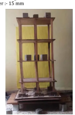
[image:6.595.104.249.138.361.2]v. Thrust bearing :- Outer diameter :- 35 mm , Inner diameter :- 15 mm
Fig -7 Deflections on left side when building is provided with springs acting as dampers & 2nd & 4th floor
(Arrangements)
7.
RESULTS
Table 1: Deflection in Building (In Cm) Time Period = 30 s.ecs.
Loading
Condition X-axis Without Dampers Y-axis X-axis With Dampers Y-axis
Building Not Loaded
2.9 3.8 2. 0.7
Building Equally Loaded On All Floor
2.3 2.7 0.7 0.3
Building Loaded On 1st And 3rd Floor
2.5 2.8 1.2 0.4
Building Loaded On 2nd And 4th Floor
2.7 3.2 1.6 0.6
8.
CONCLUSIONS
Shake tables can be effectively used to check the stability of the structure by producing ground motions similar to that during Earthquakes. The most logical method and effective protection from the overwhelming degree of acceleration induced by an earthquake is through isolation of the life bearing structures from the transmitting medium.
The above experiment has proved the effectiveness of base isolation in reducing the displacement of building during Earthquake vibrations. Thus following can be concluded from the above experiment-
1. The experimental arrangement made for inducing horizontal vibration shows that the deflection of frame in which the base is fixed is more and deflection in the frame is less in which spring has been used as dampers. 2. All the cases like 1) dead loads on first & third floor 2) dead loads on second and fourth floor 3) loaded on all floors 4) no loads shows the same results hence this experimental setup re validate the concept that dampers can be used in foundation to minimize the deflection of frames ( to minimize the stresses)
3. The effectiveness of a base isolated system depends upon the characteristics of the input excitations as well the properties of the isolation devices and superstructure. Hence, there is an essential need to do a comprehensive study to investigate the suitability of a particular base isolation system for a structure. 4. This is notable because the cost of isolation will always
be an important consideration and one of the first concerns of any project by investors. By and large, a new isolated structure costs more than a non isolated one. Also the extra engineering works in order to analyze and detailed design of the structure and its isolation system are vital. On the other hand, the flexibility of the super structure in a base isolated building is generally less than the non isolated building which can cause the reduction of construction cost.
5. However, the most significant advantage of using base isolation system is the better performance of a structure during an earthquake which can save many lives. This could be categorized as an investment for future cost savings.
REFERENCES
[1] S.J.Patil1, G.R.Reddy2 in 2001 developed (state of art review base isolation system for structures) 1 ) heavy water board, Mumbai , India 2) Bhabha atomic research centre Mumbai , India
[2] James M. Kelly , Professor Emeritus Civil and Environmental Engineering, University of California, Berkeley( developed origin & development of base isolation techniques)