© 2017, IRJET | Impact Factor value: 5.181 | ISO 9001:2008 Certified Journal | Page 2546
Seismic Analysis of Multistory Building with and without Floating
Column
Deekshitha.R
1, Dr.H.S.Sureshchandra
21
MTech Scholar, Dept. of Civil Engineering, P.E.S. College of Engineering, Mandya, Karnataka, India
2Professor, Dept. Of Civil Engineering, P.E.S. College of Engineering, Mandya, Karnataka, India
---***---Abstract –
Many buildings in recent times have plannedand constructed for architectural complexities such as building with floating columns at various levels and locations. These floating columns are highly disadvantageous in building which is built in seismically prone areas. The earthquake forces which are developed at different levels in building need to be carried down along the height to ground by shortest path, but due to floating column there is discontinuity in the load transfer path which results in poor performance of building.
In this study the analysis of G+5 storey normal and floating column building is considered and analysis is done using ETABS-2015.
This study is also to find whether the structure is safe or unsafe with building with floating column is built in seismically active areas and to find floating column building is economical or uneconomical.
Key Words: Floating column, Normal building, ETABS
1. INTRODUCTION
A column is supposed to be vertical member starting from foundation level and transferring the load to the ground. The term floating column is a vertical element which at its lower level rests on a beam which is horizontal member. The beam in turn transfers the load to other column below.
There are many buildings in which floating columns are adopted, especially above the ground floor, where transfer girders are employed, so that more open space is available in the ground floor. This open space may be utilized as party hall, assembly hall and for parking purpose. The transfer girder has to be designed and detailed properly, especially in the earthquake zones. The column acts as concentrated load on beam. As far as analysis is concerned, the column is often assumed pinned and therefore taken as point load on the transfer beam.
1.1 OBJECTIVE OF STUDY
The main objective of the proposed work is
To study the behaviour of multistory buildings with floating columns under earthquake excitations.
To find whether the structure is safe or unsafe with floating column when built in seismically active areas and also to find floating column building is economical or uneconomical.
2. MODEL DESCRIPTION
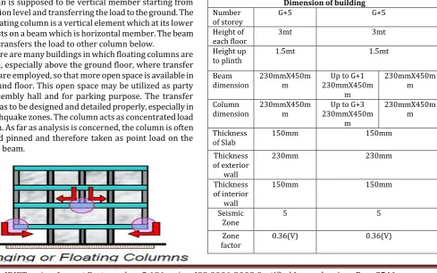
[image:1.595.70.560.480.786.2]The structure considered here is a regular building with plan dimension of 24mX24m, In this case a ground plus five storied (G+5) normal RC building were selected for the study, the buildings are considered to be located in Zone V as per IS 1893-2002. Table 1 shows the details of model and load considered.
Table -1: Geometrical dimension of building Dimension of building Number
of storey G+5 G+5
Height of
each floor 3mt 3mt
Height up
to plinth 1.5mt 1.5mt
Beam
dimension 230mmX450mm 230mmX450mUp to G+1 m
230mmX450m m
Column
dimension 230mmX450mm 230mmX450mUp to G+3 m
230mmX450m m
Thickness
of Slab 150mm 150mm
Thickness of exterior
wall
230mm 230mm
Thickness of interior
wall
150mm 150mm
Seismic
Zone 5 5
Zone
© 2017, IRJET | Impact Factor value: 5.181 | ISO 9001:2008 Certified Journal | Page 2547
Importanc
e factor 1 1
Type of
soil Medium soil Medium soil
Response reduction factor
5 5
Live load 3kN/m2 3kN/m2
Floor
finish 1.5kN/m2 1.5kN/m2
Floor load
on roof 1.5kN/m2 1.5kN/m2
Wall load on exterior
beam
12kN/m 12kN/m
Wall load on interior
beam
6kN/m 6kN/m
Grade of
Concrete 30 30
Grade of
steel Fe500 Fe500
Model-1:
Here a G+5 building with all interior columns which is nothing but a normal building is considered as model 1 with dimension of beams as 230mmX450mm and column as 230mmX450mm. For the overall building the dimension of beams and columns are kept same.
Model-2:
This building is obtained by removing the interior columns at the ground floor of model-1 building without changing in the dimensions of beams and columns. Model-2 building members are failed to withstand for the applied gravity loads and lateral loads.
Model-3:
As model-2 building is failed, so another building is created by changing the dimension of the members to make building to withstand the applied gravity loads and lateral loads. The building with changes in columns and beams is considered as model-3 building. For Mode-3 building, up to G+3 floors all column dimensions are taken as 450mmX450mm, remaining all floors may have column size of 230mmX450mm. Also all the beams will have 230mmX450mm except G+1 beam which are 300mmX450mm.
Fig-1 The Plan of Normal (G+5) storey building (Model-1)
Fig-1.1 Elevation of Normal (G+5) storey building (Model-1)
© 2017, IRJET | Impact Factor value: 5.181 | ISO 9001:2008 Certified Journal | Page 2548 Fig-3 Plan of building with columns removed in interior
frame with changes in dimension (Model-3)
Fig-3.1 Elevation of building with columns removed in interior frames
3. Comparisons
3.1 Storey Displacement
By the application of lateral loads in X and Y directions the structure can be analysed for various load combinations given by clause 6.3.1.2 of IS 1893:2002. For the given load combination maximum displacement at each floor is noted in X and Y direction and are shown in the form of graph.
Table-3.1 Displacement values of 3 Models subjected to Seismic load in X direction.
Storey Number Model 1 Model 2 Model 3
Ground floor 0.9 0.9 0.7
Storey 1 5.8 6.5 5.1
Storey 2 11.2 11.9 9.7
Storey 3 16.1 17.5 14.3
Storey 4 20 20.9 18.8
Storey 5 22.4 24.7 21.6
Fig-3.1 Displacement values of 3 Models subjected to seismic load along X direction.
Table-3.1 Displacement values of 3 models subjected to seismic load in Y direction
Storey
Number Model-1 Model-2 Model-3
Ground floor 1.2 1.1 0.6
Storey 1 8.8 10.1 4.6
Storey 2 16.5 17.6 8.8
Storey 3 23.5 24.3 13.1
Storey 4 29.1 29.7 21.8
© 2017, IRJET | Impact Factor value: 5.181 | ISO 9001:2008 Certified Journal | Page 2549 Fig-3.2 Displacement values of 3 models subjected to
seismic load along Y direction.
From the above graph it is observed that the model-2 building has more displacement when compared to a model-1 building in both X and Y directions. So model-2 is unsafe when compared to a model-1 building.
Also Model-3 building has lesser displacement than model 1 building as the dimension of beams and columns of building is varied. So model-3 building is safe in X and Y direction. 3.2 Comparison of quantity of steel and concrete:
For the three model buildings, a comparison of quantity of steel and concrete are made based on the results obtained by the analysis and design of both the buildings. Here the quantity of steel and concrete are compared only in the model 1 and 3 building because the model-2 building is unsafe and fails during design check.
For the model 1 and 3 building only the quantity of steel and concrete in beams and columns are calculated because as the thickness of slab, brick walls and all other are same and loading is also same then the comparison makes no difference between the two buildings. The sizes of beams and columns are varied in the both buildings so the comparison is based only for beams and columns.
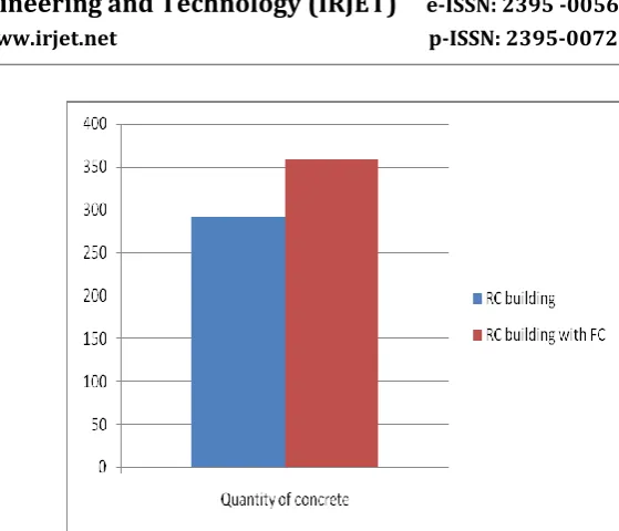
3.2.1 Calculation of Quantity of concrete
Table-3.2.1 Quantity of concrete
Model Quantity of concrete (Tones) Quantity concrete (%) of RC
building 292.3357 1
Building
with FC 358.971 22.79
Fig-3.2.1 Quantity of concrete 3.2.2 Calculation of Quantity of steel
[image:4.595.308.565.368.672.2]
Table 3.2.2: Quantity of Steel
Model Quantity steel (Tones) of Quantity Steel (%) of
RC building 12.66 1
RC building with FC 18.28 44.39
Fig-3.2.2 Quantity of steel
© 2017, IRJET | Impact Factor value: 5.181 | ISO 9001:2008 Certified Journal | Page 2550
4. CONCLUSIONS
The study compares the difference between normal building and a building with floating column. The following conclusions were drawn based on the investigation.
By the application of gravity and lateral loads in X and Y direction at each floor, the displacements of floating column building in X and Y directions are less than the normal building. Thus to improve seismic performance of the multi-storey building with floating column lateral bracings, shear walls may be provided.
After the analysis of buildings, the floating column building has 44% more rebar’s steel and 22% more concrete quantity than a normal building. So the floating column building is uneconomical to that of normal building.
The final conclusion is that do not prefer to construct floating column buildings. Also cost of construction is increased. So avoid constructing floating column buildings.
REFERENCES
1. A Textbook on”Earthquake Resistance Design of Structures” by Pankaj Agarwal and Manish Shrikhande.
2. Isha Rohilla,Gupta S.M, et.al, “ Seismic response of multi-storey irregular building with floating column”,
3. Sreekanth Gandla Nanabala, Pradeep Kumar Ramancharla, Arunakanthi E ”Seismic analysis of normal building and floating column building”IEEE trans, Power System, vol.19, no.1, pp. 356-365,2014. 4. Mundada.A.P and Sawdawar.S.G., “ Comparative seismic analysis of multistory building with and without floating column”, International Journal of current Engineering and technology, Vol-4,No5,pp 3395-3400
5. Nikil Bandwal, Anant Pande et,al. “To study seismic behavior of RC building with floating columns”, International Journal of Scientific Engineering and Technology Research”, Vol.03, issue 08,May 2014, pp 132-138
6. Srikanth M.K, Yogeendra R, Holebagilu, “Seismic response of complex buildings with floating columns for zone II and V“IEEE Trans. Power Syatem, vol.19.No 1,pp.356-365,2014
7. Prerna Nautiyal, Saleem Akhta et.al, “Seismic response evaluation pf RC frame building with floating columns considering different soil conditions”,International Journal of Current Engineering and technology, vol.4, N0.1,Feb-2014 pp 132-138
8. Sabari S, Praveen J.V., “Seismic analysis of multistoey building with floating column” IEEE Trans. Power System,vol.19, No.1, pp 356-365, 2014
9. Kavya.N, Manjunatha.K et.al, “ Seismic evaluation of multi-story RC building with and without floating column”, International Journal of Engineering Research and Technology, Vol.4.,issue 6,sep-2015,pp 361-365.
BIOGRAPHIES