© 2018, IRJET | Impact Factor value: 6.171 | ISO 9001:2008 Certified Journal | Page 1446
ANDROID BASED VOICE CONTROLLED SMART WHEELCHAIR
S. Jaanaa Rubavathy
1, P. Bavithra
2, M. Harsha Priya
3, R. Umamageshwari
41
Assistant Professor, Electrical and Electronics Engineering, Jeppiaar SRR Engineering College, Chennai, TN
2,3,4Student, Electrical and Electronics Engineering, Jeppiaar SRR Engineering College, Chennai, TN
---***---
Abstract -
WSNs have become an attractive field forresearch as well as scientific and technological developments. Wireless Sensor Networks (WSNs) comprise of a large number of tiny devices equipped with one or more sensors, some processing circuits, and a wireless transceiver. Such devices are called sensor nodes or motes. It sense the parameters like temperature, pressure, humidity, light, and chemical activity are constantly reported by these motes which are deployed and left unattended in the field. The recent development in WSNs is the concept of Smart Homes. Smart homes integrate many devices that can sense the required parameters and control the characteristics of the home. The great progress in the industry standards and installation of lightweight wireless networking hardware over a period of time has proved mobile voice input to be well suited for Smart homes and automation systems. Android application is a low cost, low power, less complex wireless standard. In this paper, sensors like temperature sensor, LPG sensor, Contact sensor are proposed to be deployed for fire detection, and determination of whether any door is closed or open, respectively.
Key Words: wireless sensor network, sensornodes ,motes Smart homes, android, contact sensors
1. INTRODUCTION
The main objective is to design a system which provides solution for the physically handicapped (challenged) people those who can’t move by themselves, using speech commands by interfacing the Speech Recognition kit with microcontroller and wheel chair.
The voice commands are given through Bluetooth with the help of mobile and the wheel chair moves according to the given directions. The movement of the wheelchair is controlled by the motors and motor drivers connected to the wheels of the chair. The interfacing between android mobile and motors is done by Microcontroller. This concept was taken in this paper to reduce the human efforts in driving a wheelchair.
2. METHODOLOGY
Our project mainly aims at alleviating the problem for the physically disabled people and helps them monitor themselves without depending on others for their life style. Present world actually aims at blending the digital world with the physical world and help people make their life easy. The present idea of our project is germane in that aspect
where we try to interface human with the machine and help him communicate with the machine.
Here input is given as a voice message. Bluetooth is used to transfer the voice message from the android to UART. Voice is recognized by voice recognition application which was installed in the android mobile. This application is only developed for controlling the wheelchair. Voice recognition application receives the voice message as input and send to the microcontroller through UART. In existing project ZIGBEE concept is used which has high cost and high power dissipation. The smart home concept is implement in the wheelchair itself which control both the action of home appliances and direction of wheel of wheelchair.
Generally patients with loss of motion and fit can't proceed onward their own particular and need extra backing, with this new approach its workable for those to screen themselves and lead a self ward life.The very caption of the IEEE states “Advancing technology with humanity” which fosters the idea of ameliorating human life with the help of technology, throwing some light on the same context it’s very necessary to involve technology in to human life and help them solve those problems. This paper also focuses on the same line to mitigate the problems faced by physically challenged people in daily life.
4.
SYSTEM DESIGN
Here we can understand the construction and working of the model. System uses an Android phone to communicate with the wheelchair and a desktop computer is used to observe the position of the wheelchair.
4.1 HARDWARE DISCRIPTION
© 2018, IRJET | Impact Factor value: 6.171 | ISO 9001:2008 Certified Journal | Page 1447
1.PIC16F874A
Pin diagram of PIC16F874A
The pins RB0-RB7, RC0-RC7, and RD0-RD7 are digital I/O pins. The pins CCP1 and CCP2, which share locations with RC1 and RC2, can be used for a PWM signal (see DC Motor tutorial). The pins AN0-AN7 are for analog I/O (see Photo resistor tutorial). TX and RX are for debugging I/O (see Output Messages to Computer tutorial). The remaining pins deal with power/ground, the clock signal, and programmer I/O. A PIC is made of several “ports.” Each port is designated with a letter, RB0-RB7 are a port. RC0-RC7 and RD0-RD7 are a port as well. RA0-RA5 and RE0-RE2 are also ports.
ULN2803
pin diagram of driver circuit
The ULN2003 is a monolithic high voltage and high current Darlington transistor arrays. It consists of seven NPN Darlington pairs that feature high-voltage outputs with
common-cathode clamp diode for switching inductive loads. The collector-current rating of a single Darlington pair is 500mA. The Darlington pairs may be paralleled for higher current capability.
RS232
UART-RS232
Serial transmission involves the sending of data one bit at a time, over a single communications line. Serial transmission is beneficial for long distance communications, where as parallel is designed for short distances or when very high transmission rates are required.
DC MOTOR
DC motor
A DC motor is designed to run on DC electric power. Two examples of pure DC designs are Michael Faraday's homoploid motor (which is uncommon), and the ball bearing motor, which is (so far) a novelty. We in our project are using brushed DC Motor, which will operate in the ratings of 12v DC 0.6A which will drive the flywheels in order to make the robot move.
POWER SUPPLY
© 2018, IRJET | Impact Factor value: 6.171 | ISO 9001:2008 Certified Journal | Page 1448
circuits that use both analog and digital signals in various ways. More importantly for our purposes, the +5 volt supply will be used as the primary reference for regulating all of the other power supplies we will build.
Schematic Diagram- Power Supply 5V The +5 volt power supply is based on the commercial7805 voltage regulator IC.
This IC contains all the circuitry needed to accept any input voltage from 8 to 18 volts and produce a steady +5 volt output, accurate to within 5% (0.25 volt). It also contains current-limiting circuitry and thermal overload protection, so that the IC won't be damaged in case of excessive load current; it will reduce its output voltage instead.
Circuit diagram of power supply
RELAY
Circuit diagram of relay
Picture of relay
A relay is an electrically operated switch. Electric through the coil of the relay creates a magnetic field which attracts a lever and changes the switch contacts. The coil current can be on or off so relays have two switch positions and there are double-throw (changeover) switches. . The P0_0, P0_1, P0_2 and P0_3 pin of controller is assumed as data transmit pins to the relay through relay driver ULN 2003. ULN 2003 is just like a current driver.
5. CIRCUIT DIAGRAM
We have already discussed the working of the components which can be seen in the circuit diagram. This is all about the hardware part of the wheelchair model.
Circuit diagram
© 2018, IRJET | Impact Factor value: 6.171 | ISO 9001:2008 Certified Journal | Page 1449
capacitor across the output terminal of the rectifier. The dc voltage is regulated by using voltage regulator. The PIC16C77A (microcontroller) is used in this project which consist of 40 pins and four ports . it control the activities of light, Fan and dc motor(16v).from four ports of PIC controller,
Port D is connected to LCD which display the status of the operation. Port C is connected to the android through UART(IC MAX232) for serial .Port B is connected to the drive circuit which consists of Darlington pair transistor to amplify the voltage which is enough to drive the load. For protection purpose relay are used between drive circuit and load.
PROPOSED HARDWARE MODULE
FIG (a)
FIG(b)
Proposed hardware
Here the proposed module consist of hardware that was described above in system design hardware description.
6. SIMULATION OUTPUT
Embedded system combines hardware and software to perform special and predefined tasks. The source code for PIC microcontroller is written in embedded C and simulated
using Proteus. According to the given voice command the motor rotates in Forward, Backward, Left and Right directions. The direction of movement of wheelchair is displayed by the LCD interfaced with PIC microcontroller
6.1 FORWARD DIRECTION
Fig6.1 Simulation for forward direction
Initially the voice message (Forward Direction) is given as an input. This input is send to the microcontroller through UART. After microcontroller receives the input, it starts its operation. Based on the voice command the microcontroller drives the dc motor. For Forward direction, Driver circuit Q1 and Q3 gets excited and rotate the motor in forward direction. Relay helps both the dc motor to run simultaneously in forward direction.
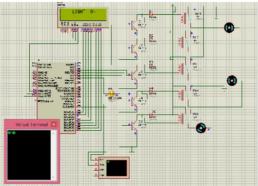
6.2 LIGHT ON
Fig6.2 Simulation for light ON
[image:4.595.308.560.518.700.2]© 2018, IRJET | Impact Factor value: 6.171 | ISO 9001:2008 Certified Journal | Page 1450
operation. Based on the voice command given to the microcontroller for LIGHT ON condition, Diode D6 gets conducted and LED glows.
6.3 FAN ON
Fig6.3 Simulation for fan ON
Initially the voice message (Fan ON) is given as an input. This input is send to the microcontroller through UART. After microcontroller receives the input, it starts its operation. Based on the voice command the microcontroller drives the dc motor. For Fan ON, Driver circuit Q5 gets excited and motor rotates. Relay helps the dc motor to run simultaneously.
7. CONCLUSIONS
The voice controlled wheel chair system is implemented as an example of companionship of human and machine. Independent movement is achieved with the help of the voice controller. It is designed to be characterized by low price and higher reliability. It is concluded that smart living will gradually turn into reality that consumer can control their home remotely and wirelessly
REFERENCES
1. W.C.Lee,Joseph Ng,L.F.Yeung,”Sensitivity Improved Zigbee RF receiver for a medical sensor”,Industrial electronics society,iecon 2013-39th annual
conference of the IEEE
2. Basma M.Mohammed El-Basioni,Sherine
Mohammed Abd El-Kader,and Hussein
S.Eissa,”Independent Living For Persons With Disablities And Elderly People using Smart Home Technology”,IEEE International conference on Application and Volume3,Issue4,April2014
3. V.Kumar,Vignesh S.N and Barathi Kannan K, “Head
Motion Controlled Robotic Wheel
Chair”,International Journal of Emerging
Technology and innovative
Engineering,vol.1,issue.3,March 2015,pp.176-17
4. V.Kumar,Vignesh S.N and Barathi Kannan K, “Head
Motion Controlled Robotic Wheel
Chair”,International Journal of Emerging
Technology and innovative
Engineering,vol.1,issue.3,March 2015,pp.176-179.
5. Vasundhara G. Posugade, Komal K. Shedge, Chaitali S. Tikhe, “Touch-Screen Based Wheelchair System”, ISSN: 2248-9622 Vol. 2, Issue 2, pp.1245-1248, Mar-Apr 2012.
6. Design of wheelchair using finger detection with image processing algorithms, Chhaya.G.Patil, Sayali.K.Gharge, Sonal.V.Modhave, Y.S.Angal, International Journal of Research in Engineering and Technology ,Feb 2014.
7. Sakshi Goyal, Ishita Sharma, Shanu Sharma, “Sign Language Recognition System For Deaf And Dumb People”, IJERT, Vol. 2 Issue 4, April – 2013.
8. Prateek Gupta “Human Voice Controlled Home Appliances” International Journal of Advanced Research in Computer and Communication Engineering,ISSN (Online) 2278-1021, Vol. 4, Issue 5, May 2015.
9. ForamKamdar, Anubbhav Malhotra and
PritishMahadik “Display Message on Notice Board using GSM” Advance in Electronic and Electric Engineering. ISSN 2231-1297, Vol. 3,pp. 827-832, Number 7 (2013.
BIOGRAPHIES
MRS.S.JAANAA RUBAVATHY
She is an Assistant Professor in Jeppiaar SRR Engineering, Chennai, Tamil Nadu. She got her Master Degree in Power Electronics and Drives in Sastha Engineering College, Thanjavur, Tamil Nadu.
P.BAVITHRA
© 2018, IRJET | Impact Factor value: 6.171 | ISO 9001:2008 Certified Journal | Page 1451 M.HARSHA PRIYA
Pursuring Degree in Electricals and Electronics Engineering in Jeppiaar SRR Engineering College, Chennai, Tamil Nadu.
R. UMAMAGESHWARI