Autonomous Mobile Robot Navigation by
Combining Local and Global Techniques
Shahida Khatoon and Ibraheem
Department of Electrical Engineering Faculty of Engineering and TechnologyJMI, New Delhi-25, INDIA
ABSTRACT
The present article is devoted to develop an algorithm for obstacle avoidance of an autonomous mobile robot based on fuzzy logic/ The method of navigation proposed provides a way of blending the intelligence and optimality of global methods with the reactive dynamic behavior of local ones. This is achieved by using hybrid navigation system composed of two modules, one of which uses the a-priori information and determines roughly the optimal route towards the goal, whereas the other carries out effective navigation decisions using the potential function based local approach. The fuzzy rules are constructed from intuitive and subjective human ways of collision avoidance. The results of the present study are compares favorably with those of well-established algorithms.
Keywords:
Autonomous robot system, reactive navigation, goal seeking, open area seeking, obstacle avoidance, fuzzy subset1. INTRODUCTION
Mobile robot autonomous navigation is a currently active area of robot research. Many navigation approaches have been developed by robotic researchers with the aim of controlling robots to successfully navigate in unknown, unstructured environment. One of the most important functions of mobile robots operating in such environments is its ability to avoid collision. For this it uses one of the two well-established approaches namely global approach and local approach. A navigation method is said to be global if it calculates the whole trajectory at the beginning of the navigation task, and whenever a new situation arises. A global algorithm has the ability to take into consideration every detail of the navigation map therefore yields a more intelligent result than local ones. However, a global algorithm has the following drawbacks:
(i) Robots with a global navigation algorithm can only reach goal positions that are located on it‟s a-priori known map.
(ii) It requires a detailed knowledge of the environment. Perceiving an obstacle that has been moved into a previously free area can cause the
(iv) This may result in a large quantity of resources being used up needlessly
There are global trajectory planning methods, generally based on previously existing optimization algorithms – that are able to find optimal trajectories according to various optimality criteria [83, 86]. The method described in [86] considers two objectives: that the robot should pass as far from the obstacles as possible, and that the trajectory should be as short as possible – the weighting of these two is determined by a constant.
Most previous dealings with global navigation method suggest the avoidance of such dynamic situations instead of away of resolving them. Local algorithms respond well to the challenges posed by the global methods, as they decide the navigation course using current sensor information [10,84,85]. Most local navigation algorithms have the principal aim to navigate in a safe way, to avoid all the obstacles that appear during the navigation, while they usually continue to approach goal. Still they have the following demerits:
(i) A local algorithm never calculates parts of the trajectory in advance.
(ii) A local navigation algorithm does not guarantee an optimal trajectory.
(iii) There may always be situations – local minima – where a local algorithm will even fail to find the target position.
In spite of these, if obstacles are reasonably rare, a local navigation algorithm may prove to be the best solution. This is also the case when we have no a priori information on the navigation environment.
also dynamic, thus unknown at times, impose the contradicting requirements of using both the a priori data and the momentary sensor data on the robot‟s navigation system. The solution proposed in this thesis resolves this contradiction by using a hybrid method, which can blend the reactivity of local methods with the intelligence and optimality of global ones. The idea is to use global planning to determine only certain points- temporary goals- where the robot need to pass to reach the goal without getting stuck, and then do the actual navigation by a local algorithm. As shown in Fig. 5.1, under the normal circumstances, the supervised block (below, dashed lines) is not present, but it can be used in a possible teaching phase. As a local algorithm is used, the risk of local minimum situations remains, but it is greatly reduced by providing specific target positions that are always in the same region as the robot itself.
Global Planner
Local Navigator
Supervisor
Movement Map
Sensors
Required movement Obstacle
Data
Success/failure Intermediary
goal
Goal position Map data
Fig. 1 Main parts of the navigation system
In addition, global information is also used to supervise the navigation – re-plan temporary goals if an unexpected situation occurs, a door is blocked etc. – and thus local minimum situation can be resolved.
1.2
Related Work
Besides the research articles based on the conventional techniques in the early stages of researches last twenty uears have witnessed a tremendous interest of application of fuzzy logic in the area of autonomous mobile robot navigation [1-27]. Perhaps Takagi [] and Sugeno [] were the first to introduce the idea of deriving fuzzy control rules by modeling an expert‟s deriving action way back in 1983. Later, Sugeno and Nishida [66] demonstrated a first fuzzy logic controlled car based on this concept in 1985, which can move smoothly along a crack-shaped path. The improved version of this car was reported in [71,104]. The version was having ultrasonic sensors to measure the distances to walls and objects in front, and fuzzy control rules were designed by referring to an operator's experience and knowledge. The car is controlled by the
oral instructions such as "go straight", "turn right:, "enter garage", and so on. In 1988, a new obstacle avoidance control system was proposed by Takeuchi et al [101] for a mobile robot. The charged coupled device (CCD) camera was used to process the floor image as inputs to the fuzzy controller.
The mobile robot presented in [5] is capable to move from a start position to a goal position, avoiding local collisions. The open area seeking approach has been used for the navigation system. However, there was no mention of goal seeking approach in the work. In [24], a fuzzy VLSI-chip on-board to control an omni directional mobile robot is used using goal seeking approach where as in [41], a fuzzy control algorithm for obstacles avoidance based on sub-goal-seeking approach is presented.
Seraji [] presented the behavior-based architecture for mobile robot navigation
2. SYSTEM CONFIGURATION
The proposed fuzzy logic based control scheme of a non-holonomic mobile robot has been simulated with sensory system consisting of a set of distances measuring IR sensors based on following assumptions;
(i) The parameters relating to models of robot kinematics and dynamic constraints are measurable and observable.
(ii) The sensory system is capable to provide all input data that are required for the implementation of proposed control strategy
2.1 The sensory system
The sensory system is of rangefinder type. The measurement of distances to the target position and direction in which the target is located is based on the output of the IR rangefinder. The output of rangefinder is a set of angle (φ) and distance (d) to the target around the robot. The task of the data processing unit is to convert the set of (φ, d) into data that can be used for obstacle avoidance. It judges the directions in which the main goal, the obstacles, and the favored open area exist. Therefore, outputs of the sensor system are ;
(i) The goal direction with respect to the mobile robot (ii) The open area (gate) direction with respect to the
robot
(iii) The distances between the robot and the obstacles
2.2 The Mathematical Model
L
y
Fw
R
F
O
w
Figure2: Mathematical model of the car like robot
However, it can not move sidewise and its turns are usually limited by mechanical stops in the steering gear. Nevertheless, it can take any position and orientation in plane. Usually, modeling is done for a car-like robot as rectangular object moving in two-dimensional space (Refer to Fig. 2). Experience has proved that in an empty space the robot can be driven to any position with any orientation. Hence the robot‟s configuration space has three dimensions, two of translation and one for rotation. Let us represent a configuration of A by (x, y,), where x and y are the coordinates, in the frame Fw, of midpoint R between the two rear wheels and [0, 2] is the angle between the x-axis of Fw, and the main axis of A.
At any point during a motion, assuming no slipping, the velocity of „R’ has two points along the main axis of A. Therefore, the motion is constraint by the relation: - sin dx + cos dy = 0 (1)
It can be shown that this equation is non-integrable, hence is a nonholonomic equality constraint. Due to this constraint, the space of differential motion ( dx, dy, d ) of the robot at any configuration (x, y, ) is a two-dimensional space. If the robot were a free-flying object, this space would be three-dimensional. The instantaneous motion of a car-like robot is determined by two parameters: the linear velocity along its main axis and thew steering angle. However, when the steering angle is non-zero, the robot changes its orientation, and its linear velocity with it, allowing the robot‟s configuration to span a three
Simple kinematics equations that represent the robot motion are used. If the mobile robot moved forward form (x, y) position to (x', y') position at iteration, then the following kinematics will represent the mobile robot motion:
' = + (2)
y' = y + speed * sin (' ) (3)
x' = x + speed * cos (' ) (4) where is the robot direction, and is the steering angle. The following interval values are assumed for each variable to use in simulations:
x (0,50) y (0,100) [ -900, 2700 ]
At each control cycle the outputs of the controller are the steering angle , and the speed of the robot. We suppose that the speed will range from 0 to 2 meter per second. Where [ -40, 40 ] .
3.
FUZZY
ALGORITHM
FOR
OBSTACLE AVOIDANCE
If the robot intends to move from a start position to a target position in a-priori unknown and unpredictable environment, initially, it will move towards the target position. For this, a global approach is used. While moving, if the rangefinder sensor detects any obstacle (blocked area) ahead on, then it will try to avoid this obstacle by changing it's direction and by turning the robot's motion away from the obstacle and towards, i.e. the widest, open area. Here, the local approach based navigation technique will be used. The direction at this stage will be parallel along the obstacle and towards the open area until the robot reaches the end of the obstacles‟ edge. Now the robot will try to seek the target position again, and so on.
Min-r Min-l
Robot
Obst acle2 Obst acle1
T gt -dir Gat e-dir
dist ance
T arget
Fig. 3: Autonomous robot simulated environment
3.2
Fuzzy
Logic
Based
Control
Scheme
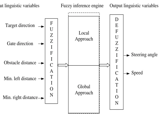
A fuzzy logic based control scheme developed in the present work is shown in Fig. 3. The scheme consists of four components namely;
(i) fuzzification module (ii) inference machine (iii) rule/data base (iv) defuzzification module
3.3
The Linguistic Variables
The input and output variables are considered as linguistic variables. The following variables are identified as input variables for the system under study (Table 1). The controller produces two output variables considered as linguistic variables (Table 2)
Table 1 Input variables
Symbols for input variables
Description
Tgt-dir The direction of the target with respect to the mobile robot.
Gate-dir The direction of the open area with respect to the mobile robot.
Obst-dist The distance between the mobile robot and the nearest obstacle.
Min-l The distance between the mobile robot and the obstacle which is on the left side of the robot.
Min-r The distance between the mobile robot
and the obstacle which is on the right side of the robot.
Table 2 Output variables
Symbols for Output Variables
Description
The steering angle of the mobile robot
v The mobile robot speed.
F
U
Z
Z
I
F
I
C
A
T
I
O
N
Target direction
Gate direction
Obstacle distance
Min. left distance
Min. right distance
Local
Approach
Global
Approach
D
E
F
U
Z
Z
I
F
I
C
A
T
I
O
N
Steering angle
Speed
Fuzzy inference engine
[image:4.595.89.267.242.397.2]Input linguistic variables
Output linguistic variables
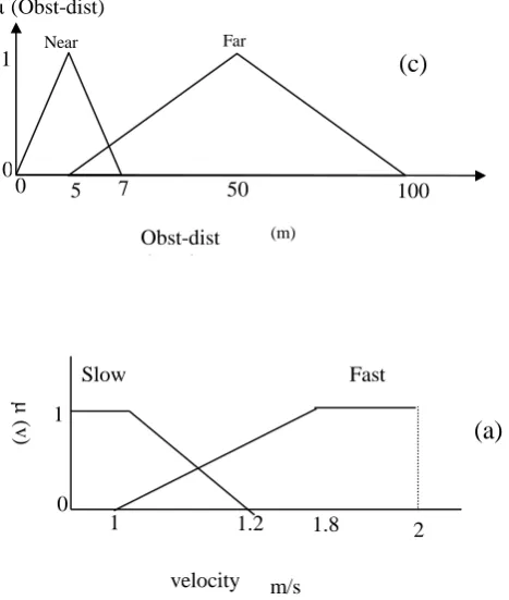
[image:4.595.106.501.269.733.2] [image:4.595.301.530.274.475.2] [image:4.595.131.466.497.734.2]Each of the above input variables is converted into its corresponding linguistic fuzzy set as shown in Table 2, the corresponding membership functions are graphically depicted in Fig. 4
Table 3 Input linguistic fuzzy sets
Table 4 Output linguistic fuzzy sets
Symbols for input variables
Linguistic fuzzy set Ranges in m/s,
radians
(Triangular fuzzy membership func) Velocity of robot Slow, Fast (0,1,1.2) , (1,1.8,2) Steering angle Extreme right (R
Right), Right, Straight, Left, Extreme left (L Left)
(-40,-20) , (-40,-20,0) , (-5.0.5), (0,20,40), (20,40)
Each of the above output variables is converted into its correspondinglinguistic fuzzy set as shown in Table 4, the corresponding membership functions are graphically depicted in Fig. 5
3.4
Pictorial Representation of Fuzzy
Membership Functions
The input linguistic fuzzy variables (Table 5.3) have following membership variations
Short
1
(min_l)
0
0 7
(m)
Min-Left Distance 4
(a)
Short
1
(min_r)
0
0 7
(m)
Min-Right Distance 4
(b)
Near
1
(Obst-dist)
0
0 7 50 100
Far
(m)
Obst-dist (Steering) 5
(c)
Slow Fast 1
(v
)
(a)
Symbols for input variables
Linguistic fuzzy set Ranges in meters (Triangular fuzzy membership func)
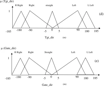
Tgt-dir Extreme right (R Right), Right, Straight, Left, Extreme left (L Left)
(-185,-180,-90) , (-180,-90,0) ,(-5.0.5), (0,90,180), (90,180,185) Gate-dir Extreme right (R Right),
Right, Straight, Left, Extreme left (L Left)
(-185,-180,-90) , (-180,-90,0) ,(-5.0.5), (0,90,180), (90,180,185)
Obst-dist Near, Far (0,5,7) , (5,50,100)
Min-l Short (0,4,7)
[image:5.595.62.302.134.387.2] [image:5.595.185.419.460.736.2]R Right
1
(Tgt_dir)
0
-180 -90 -5 0 5 90 185
Right straight Left L Left
(m)
Tgt_dir (Steering)
180 -185
(d)
R Right
1
(Gate_dir)
0
-180 -90 -5 0 5 90 185
Right Straight Left L Left
(m)
Gate_dir
180 -185
(e)
Fig. 5(a-e) Membership functions of the input variables
The output linguistic fuzzy variables (Table 5.4) have following membership variations
R Right
1
()
0
-40 -20 -5 0 5 20 40
Right Zero Left
L Left
deg.
(Steering)
(b)
Fig. 6(a, b) Membership functions of the output variables
3.5
Fuzzy Rule Base
The fuzzy if-then rules are constructed to represent the model of the present control problem of autonomous mobile robot navigation. These fuzzy if-then rules are listed in Table 5
Fuzzy-Rule Description of Rule set
Rule #1 If Gate-dir is R Right and Obst-Dist is Near then is R Right
Rule #2 If Gate-dir is Right and Obs-dist is Near then is Right
Rule #3 If Gate-dir is Straight and Obst-dist is Near then is Zero
Rule #4 If Gate-dir is Left and Obst-dist is Near then is Left
Rule #5 If Gate-dir is L Left and Obst-dist is Near then is L Left
Rule #6 If Tgt-dir is R Right and Obst-dist is Far then is R Right
Rule #7 If Tgt-dir is Right and Obst-dist is Far then is right
Rule #8 If Tgt-dir is Straight and Obst-dist is Far then is Zero
Rule #9 If Tgt-dir is left and Obst-dist is Far then is Left Rule #10 If Tgt-dir is L Left and Obst-dist is Far then is L
Left
Rule #11 If Min-l is Short then is Right Rule #12 If Min-r is Short then is Left Rule #13 If Obst-dist is Near then v is Fast Rule #14 If Obst-dist is Far then v is Slow
Table 5 Fuzzy if-then rules
[image:6.595.127.472.78.365.2] [image:6.595.66.292.618.764.2]4.
SIMULATION
RESULTS
AND
COMPARISON
WITH
PREVIOUS
WORK
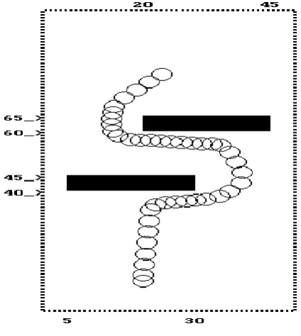
The proposed novel algorithm for obstacle avoidance has been implemented on PC-Pentium IV. The simulation programs were written in C-language. We have made several simulation runs to test the algorithm. Fig.s 5.6 to 5.9 show different environments simulated for mobile robot to prove its navigation ability. Robot behavior against four different obstacle patterns was examined namely,
1. Two Obstacles Pattern 2. Narrow Corridor Pattern 3. Many Obstacles Pattern 4. Blocked Corridor Pattern
The first environment consists of two obstacles being laid in the robot‟s path. Secondly it is made slightly complex by placing a narrow corridor in robot‟s trajectory. Thirdly the robot is required to sway through a bunch of obstacles. Lastly a blocked corridor is provided to the robot to examine its ability to recognize a blocked area ahead. This pattern may create a "dead-lock" problem through the blocked corridor, where the mobile robot cannot avoid this problem before getting into the blocked corridor. The reason is that the robot does not have the high-level map reading ability like a human being thus moves in a very "short-sighted" manner.
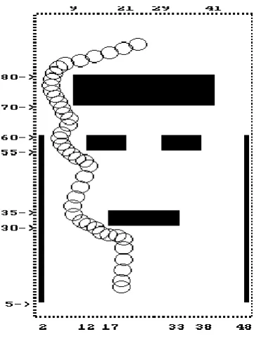
Fig. 7.1 Two obstacle pattern with target
Fig. 7.2 Two obstacle pattern with target point at left
[image:7.595.315.525.70.275.2] [image:7.595.310.533.314.518.2] [image:7.595.77.289.415.652.2]Fig. 7.4 Narrow corridor pattern with target point at right
Fig. 7.5 Many obstacle pattern with target point at right
Fig. 7.6 Many obstacle pattern with target point at center
Fig. 7.7 Blocked corridor pattern with target point up
[image:8.595.74.290.70.317.2] [image:8.595.321.524.71.320.2] [image:8.595.94.280.371.612.2] [image:8.595.313.544.375.630.2]represent higher speed. The second pattern (Fig. 7.2) is a narrow corridor. The results show that the same algorithm is applicable to this situation. The third environment is a more complex environment. The robot is required to sway through a bunch of obstacles, as illustrated in Fig. 7.3. As can be seen, the trajectory that the robot drew is not the optimum path because of obstacles. The fourth environment consists of obstacles with blocked corridor. The simulation result for this environment is shown in Fig. 5.12. This pattern may create a "dead-lock" problem through the blocked corridor, where the mobile robot cannot avoid this problem before getting into the blocked corridor. The reason is that the robot does not have the high-level map reading ability like a human being thus moves in a very "short-sighted" manner.
5. COMPARISON WITH EARLIER
WORK
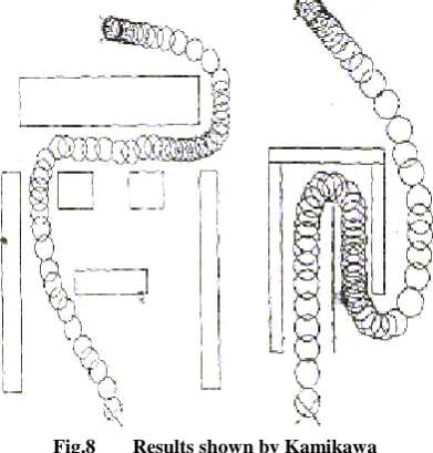
A comparison between our results and the results obtained by other authors is now presented. The results obtained by Kato and Kamikawa [5] algorithm for obstacle avoidance problem is based purely on open-area seeking idea (Fig. 7).
Fig.8 Results shown by Kamikawa
Comparing their results with Fig. 7.1 to 8, we note that the path selected by the robot in [5] is fixed because it always seeks the same open area, where as our method is more flexible to select the path that is used by the robot because the movement trajectory is based on the position of the mobile robot with respect to the nearest favorable open area and the main goal. However, the trajectory chosen in the method of Kato and Kamikawa is smooth and the path that is chosen is sometimes shorter than in our method, because the robot seeks the area directly before it becomes close to any obstacle.
model is capable of approximating nonlinear continuous function on a set of rules An algorithm based on fuzzy logic control concept is proposed. The algorithm incorporates the goal-seeking scheme as well as open area seeking technique. Four different types of obstacle patterns are considered for the implementation of the proposed algorithm. The patterns are having many possible types of obstacles and arranged in different combinations. The algorithm is tested successfully for several structures of the obstacle environment for mobile robot navigation.
7. REFERENCES
[1] T. Takeuchi, Y. Nagai, and N. Enmoto, “Fuzzy Control of Mobile Robot for Obstacle Avoidance”, Information Sciences 45, 1988, pp 231-248.
[2] M. Maeda, Y. Maeda and S. Murakami, “Fuzzy Drive Control of Autonomous Mobile Robot”, Int. J. Fuzzy Sets and Systems 39, North-Holland, 1991, 195-204. [3] A. Kato and K. Kamikawa, “Obstacle Avoidance
Based on Approximate Reasoning for Mobile Robots”, IEEE Workshop on Intelligent Robots and Systems, 1989, Tasukuba, Japan, pp 115-121. [4] F. G. Pin, H. Watanabe, J. Symon and R. S. Pattay,
“Autonomous Navigation of a Mobile Robot Using Custom-Design Qualitative Reasoning VLSI Chips and Boards”, Proc. IEEE Int. Conf. On Robotics and Automation, Nice, France, 1992, pp 123-128. [5] J. Zhang, and P. Bohner, “A fuzzy Control Approach
for Executing Sub goal Guided Motion of a Mobile Robot in a partially-Known Environment” Proc. IEEE Int. Conf. On Robotics and Automation, Atlanta, Georgia, USA, Vol. 2, 1993, pp 545-550.
[6] M. Sugeno and M. Nishida, “Fuzzy Control of Model Car”, Int. J. Fuzzy Sets and Systems 10, North-Holland, 1985, 103-113.
[7] M. Sugeno, T. Murofushi, T. Mori, T. Tatematsu, and J. Tanaka, “Fuzzy Algorithmic Control of a Model Car by Oral Instructions”, Int. J. Fuzzy Sets and Systems 10, North-Holland, 1989, 207-219.
[8] B. Kosko, “Neural Networks and Fuzzy Systems”, Prentice-Hall, 1992.
[9] Takagi and M. Sugeno, “Fuzzy Identification of Systems and its Applications to Modeling and Control”, Trans. On Systems, Man, Cybernetics, Vol. SMC-15, No. 1, Jan/Feb. 1985, pp 116-32.
[10] T.Takagi and M. Sugeno, “Derivation of Fuzzy Control Rules from Human Operator‟s Control Actions”, IFAC Fuzzy Information, Marseill, France, 1983, pp 55-65.
[image:9.595.82.278.320.525.2][13] Pertu Rusu, Emil M. Petriu, Thomas E Whalen, Aurel Cornell and Hans J. W. Spoelder “ Behavior-Based Neuro-Fuzzy Controller for Mobile Robot Navigation ”, IEEE Transactions on Instrumentation and Measurements, Vol. 52, No. 4, August 2003, pp 1335-1340.
[14] H. Seraji and A. Howard, “Behavior Based Robot navigation on Challenging Terrain: A fuzzy Logic Approach”, IEEE Transactions on Robotics and Automation, Vol. 18, No. 3, pp.308-321, June 2002 [15] M. F. Azeem, M. Hanumandlu, N Ahmed, “
Generalization of adaptive neuro-fuzzy inference systems”, IEEE Transactions on Neural Networks, Vol. 11, No. 6, pp. 1332-1346, Nov, 2000.
[16] M. F. Azeem, M. Hanumandlu, N Ahmed, “ Structure identification of generalized adaptive neuro-fuzzy
inference systems”, IEEE Transactions on Fuzzy Systems, Vol. 11, No. 5, pp. 666-681, October, 2003. [17] Michael Seelinger, John-David Yoder, T. Baumgrtner,
and Steven B. Skaar, “ High-Precision Visual Control of Mobile Manipulators”, IEEE Transactions on Robotics and Automation, Vol. 18, No. 6, pp. 957-965, Dec. 2002.
[18] S. B. Goldberg, M. W. Maimone and l. H. Mattheis, “ Stereo vision and rover navigation software for planetary explorations ”, Proc. IEEE Aerospace Conference, Big Sky, MT 2002.