http://dx.doi.org/10.4236/wjm.2015.57014
How to cite this paper: Kubota, Y. and Mochizuki, O. (2015) Splash Formation Due to a Frog Diving into Water. World Jour-nal of Mechanics, 5, 129-137. http://dx.doi.org/10.4236/wjm.2015.57014
Splash Formation Due to a Frog Diving
into Water
Yoshihiro Kubota1*, Osamu Mochizuki2
1Faculty of Science and Engineering, Toyo University, Saitama, Japan 2Department of Biomedical Engineering, Toyo University, Saitama, Japan
Email: *[email protected]
Received 24 May 2015; accepted 20 July 2015; published 23 July 2015
Copyright © 2015 by authors and Scientific Research Publishing Inc.
This work is licensed under the Creative Commons Attribution International License (CC BY).
http://creativecommons.org/licenses/by/4.0/
Abstract
Herein, we present the results of our experimental investigation of splashes formed by a frog di-ving into water from the ground or from a leaf and the accompanying sound generated by the im-pact of the frog on the water. The experiments are performed by visualizing the flow with a high- speed camera. In addition, we used physical models comprising hydrophilic bodies made from hydrogel or acrylic resin to experimentally study how hydrophilicity affects the splash. In these experiments, we use the degree of swelling to define the hydrophilicity degree. The results show that different splashes are caused by the increase in water-film velocity upon an increase in hy-drophilicity. For a body with strong hydrophilicity, at a relatively high film velocity, the water film forms when the body impacts the water surface separates from the body surface. In addition, an aircavity forms when the film separates from the body. We empirically examine the relation be-tween the hydrophilicity degree and film velocity. The results indicate that increased hydrophilic-ity does not reduce the splash. Therefore, we conclude that reducing of the formation of water from the biomimetic point of view is related to the shape of body.
Keywords
Frog Dive, Splash Formation, Flow Visualization
1. Introduction
the slip of flow.
A water droplet impinging on a solid surface also generates a splash. Yoon et al. studied the film-like struc-ture of such splashes and its instability [6]. In a related work, Bejan et al.[7] and Bussmann et al.[8] used expe-rimental and numerical means respectively to study the deformation of a droplet impinging on a solid surface. Bussmann et al. used the Rayleigh-Taylor instability theory to discuss the number of fingers that appeared at the edge of a spreading film. In our previous work [4], we show that instability is related to the number of droplets generated at the edge of the film flow. For a sphere plunging through a water surface, such droplets are generat-ed by the primary splash that appears during the first stage of the splash. This work was relatgenerat-ed to that of Wor-thington [9], who investigated the milk crown caused by a droplet-liquid collision and the splash caused by a solid body falling into liquid milk [9]. Akers et al. [10] studied the splash of a non-Newtonian fluid [10] and showed how air cavities deform as a function of fluid properties. Ahn et al. investigated the influence of surface condition as the strength of hydrophobicity for splash erosion of soil model [11]. Finally, Truscott et al.[12] in-vestigated the splash formed when a spinning spherical body plungeed into water, focusing particularly on the formation of underwater air cavities. Eddington et al. (2003) reported using the hydrogel as a valve for flow control on micro channels [13].
Thus, although the splash phenomenon is familiar, the detailed mechanisms behind it are not yet well unders-tood. Because frogs dive into water often to escape predators and ensure their own survival, evolutionary rea-soning suggests that their splash should be minimized. Thus, we used a high-speed camera to observe the vari-ous splashes formed by the diving of two frog species as a function of their habitat. We also recorded the sound generated by the splashes to investigate the relation between splash formation and the dive. In addition, to better understand how the hydrophilicity of a body with a hydrophilic surface (e.g., the body of a frog) affects the splash, we experimented with two homogeneous inanimate physical objects made of materials with different hydrophilicities. On the basis of these experimental results, we explain how the surface of an object affects its splash by modifying the process by which water films form. We also discuss splash formation as a function of the frog-dive technique and how hydrophilicity affects the splash and the film-flow velocity as a frog dives into water. Splashes were visualized using a high-speed CMOS camera. The tested materials are acrylic resin and a hydrogel as the hydrophilic body. These materials result in a distinctive affinity of body and water.
2. Splash Patterns
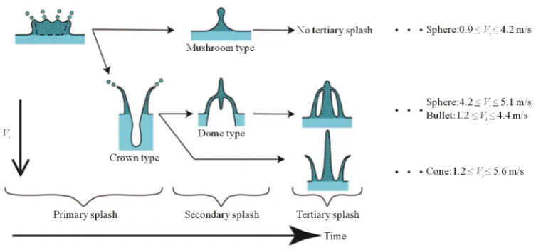
Figure 1. Tree diagram of splash formation for different impact velocities and object shapes.
above the object, the secondary splash takes the form of a dome. If the film does not recombine behind the ob-ject, no secondary splash appears. Finally, the tertiary splash appears because of the air cavity that forms when the object enters the water with sufficient speed. If no air cavity forms, no tertiary splash appears. The air cavity is related to the detachment of the film from the surface of the object. Thus, the primary splash strongly affects all subsequent splash processes.
In a previous work [14], we showed how the tail shape of the primary splash affects the secondary splash. More specifically, we reported how the shape of an object and film recombination are related to second-ary-splash formation. The tail shape affects the volume of the secondary splash and the time delay between the primary and the secondary splash. We also investigated [15] how the head shape affects the formation of subse-quent splash events by studying film formation as a function of the head shape. In that work, we examined the film thickness as a function of the momentum of the body and the film.
3. Experimental Setup
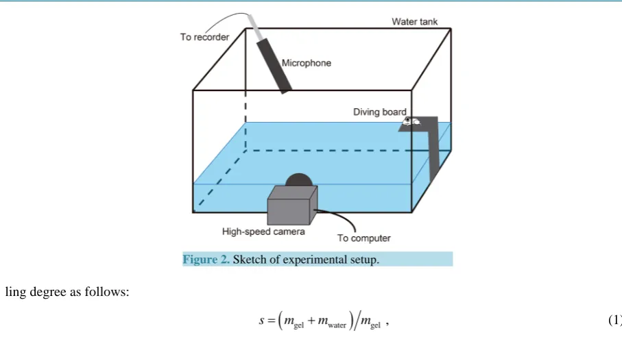
3.1. Splash from Frog DiveFigure 2 shows that the sketch of experimental setup. The experiments with live frogs were performed in a wa-ter tank measuring 240 × 200 × 450 mm3 and filled with tap water to a depth of 100 mm. Side-view sequential images were acquired by a high-speed CMOS camera(Vision Research Inc., Miro ex4).This camera allows 1200 images to be captured per second (1200 frames per second, or fps). A 500-W halogen lamp was used to illumi-nate the flow field. The sound due to the frog dives into water was recorded.
Two species of frogs, Rana porosa and Hyla japonica, were used in this experiment. R. porosa lives near flooded paddies, and H. japonica lives in trees. The different body shapes and surfaces are useful for under-standing frog dives. For both frog species, the body length L (i.e., from nose tip to rear of body) was 50 mm, and the body width W was 20 mm. The initial height of the diving board was 0 W, 2.5 W, and 5 W, where 0 W means that the diving board was at the level of the water surface. The frogs’ impact velocity Vi was determined by im-age analysis and varied from 1.7 to 2.2 m/s. The frog motion is not restricted during the experiments.
3.2. Splash from Inanimate Objects
To observe splashes from a solid inanimate object plunging into water, we used a water tank measuring 300 × 300 × 400 mm3 and filled it with tap water to a depth of 340 mm. In a previous work [4], we confirmed that contaminants common to tap water do not affect splash formation. To acquire sequential side-view images of splash formation, we used a high-speed CMOS camera (Vision Research Inc., Phantom v7.1) set at 4000 fps. The each frame was exposed for 0.25 ms. A 500-W halogen lamp was used to illuminate the scene.
Figure 2. Sketch of experimental setup.
ling degree as follows:
(
gel water)
gels= m +m m , (1)
where mgel(mwater) is the mass of gel(water). We consider swelling degrees s = 1, 50, and 100 (s = 1 means no water is contained in the object (e.g., an acrylic object)).
Before each experiment, we carefully wiped the surface of each object with paper towels to remove contami-nants such as oil and to ensure similar surface conditions for each experiment. The impact velocity Vi of the ob-ject, which is the velocity of the object just before it enters the water, was varied by changing the height h from which it was dropped. Here h is defined as the distance from the water surface to the bottom of the object. The initial height h was varied from 1D to 45D, which resulted in Vi ranging from 0.63 to 4.2 m/s. The value of Vi was calculated using Vi = (2gh)1/2, which is based on the conservation of energy. Air drag was neglected in this calculation because of the low air speed involved. A launcher system using suction held the object at the initial height before release, and all objects fell into water without rotating and with no horizontal displacement. Thus, the experiments are all repeatable.
4. Experimental Results
We used three dimensionless parameters to understand splash formation: dimensionless time, Reynolds number, and Weber number. The dimensionless time T is defined as T =tV Di , where t is the measured time. This
ap-proach is useful for comparing how splashes form as a function of Vi. Even if Vi varies, the dimensionless time T = 1 indicates the same dimensionless time interval during which the object moves a distance of one diameter D. The dimensionless time T = 0 indicates the moment when the head of the objects touches the water surface. Further, Reynolds number Re and Weber number We are useful for understanding the relation between the ki-netics of the object and the fluid characteristics. The former is defined as Re=V Di νi, where ν is the kinematic
viscosity of water at 25˚C, and the latter is given by 2 i
We=ρV D σ , where ρ is the density and σ is the surface tension of water at 25˚C.
4.1. Splash from Frog Dive
Figure 3 shows consecutive images of the dive of an R. porosa frog into the water with an impact velocity of Vi = 1.7 m/s (h/W = 0) and the accompanying audio waveform. Figure 3(a) shows that the frog dives into the water head first. Figure 3(f) shows the final phase of the dive. The significant event in the dive is the air bubbles se-parating from the body. The audio waveform accompanying the dive is shown in the bottom part of Figure 3
[image:4.595.215.415.84.257.2][sec.]
Figure 3. Images showingthe diving sequence of R. porosa. Shown at the bottom of the figure is the associated audio waveform.
Figure 4 shows the sequential images of the splash from the dive of an H. japonica frog. H. japonica enters the water first with its abdomen. Diving abdomen first produces a larger air cavity under the water, and the se-paration from the body of the cavity generates more small air bubbles than in the case of R. porosa. The audio wave form shown at the bottom of the figure again reveals two significant signal bursts, as in the case of the R. porosa dive. The initial audio burst occurs when with the body impacts the water and the second audio burst occur when the air bubbles form.
A stronger audio signal occurs at point (c) for H. japonica than at the corresponding point in the dive of R. porosa. This point corresponds to the formation of air bubbles, as seen clearly in the corresponding image. The different bubble formation for the two dives is due to the diving posture of each frog. Our previous works [12] [13] show that the shape of an object is related to the form of the air cavity created and the splash. Note that R. porosa lives near flooded paddies and that H. japonica lives in trees. This difference determines in large part how each frog escapes from its predators: R. porosa must escape as quietly as possible. Thus, the body posture during the dive influences the formation of air bubbles by determining at which point the air cavity separates from the body. In the next section, we use experiments with inanimate physical objects to discuss how the hy-drophilicity of an object’s surface affects the splash created when it plunges into water.
4.2. Effect of Splash Formation with a Surface Condition
The hydrophilicity degree of a body is quantified in terms of the swelling s, which is defined in Equation (1).
Figure 5 compares the splash formed by objects having the same shape (spherical) but differing in their degree of swelling. These images correspond to the dimensionless time T = 2.0. The acrylic body (Figure 5(a)) has s = 0 because it contains no water in its body. Figure 5(b) and Figure 5(c) show the results for the hydrogel objects with s = 50 and 100, respectively. For all three objects, a film forms when the object hits the water surface and the droplets are generated at the edge of the film. The splash for s = 0 is of the mushroom type, where the film recombines behind the object. A mushroom-type splash forms when no underwater air cavity forms. The splash for the hydrogel for s = 50 and 100 is of the dome type. The dome-type splash forms when the body completely penetrates the water surface before the film covers the body. Note that the depth of the air cavity differs for s = 50 and s = 100. This depth is greater for greater hydrophilicity (i.e., for s = 100), which means that the hydro-philicity degree of an object’s surface affects the velocity of film flow. To better understand the relation between film velocity and swelling, we measured the film velocity as a function of swelling.
[sec.]
Figure 4. Images showingthe diving sequence of H. japonica. Shown at the bottom of the figure is the
[image:6.595.115.514.81.291.2]associated audio wave form.
Figure 5. Comparison of splash formation at Vi = 3.1 m/s. (a) s = 0 (acrylic resin); (b) s = 50; and (c) s = 100.
film separating from the surface of the object [4]. The film separates when the centrifugal force acting on the film becomes greater than the surface tension of the film [4] [15]. The film velocity increases with swelling, which indicates that hydrophilicity is related to splash formation. Thus, we need to understand the relation be-tween the hydrophilicity degree and splash formation.
Figure 6(b) shows the relation between film velocity and swelling. The red circles show the results of expe-riments, and the blue line shows the empirical function Vfmax = 0.98 ln(s). The empirical function is obtained on the basis of the evidence shown in Figure 5 that film velocity increases with hydrophilicity. Figure 5 also re-veals that the depth of the air cavity increases with an increase in swelling, which means that amore hydrophilic surface leads to a deeper air cavity. Thus, the air cavity must be considered in addition to the impact velocity to determine the potential energy of the system and the film velocity. Therefore, a combination of impact velocity and film velocity affects the tertiary splash, because the tertiary splash forms from the air cavity. In addition, the empirical curve is consistent with the experimental data. Thus, the film velocity of a hydrophilic object can be expressed as a logarithmic function of the swelling of the object.
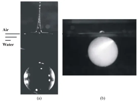
If the impact velocity is less than 0.9 m/s, then a spire-type splash forms because of the concavity of the water surface [4]. From the relation between film velocity and impact velocity, we infer that the film velocity at a low impact velocity increases. This means that the impact-velocity threshold between spire- and mushroom-type splashes (Vi < 0.9 m/s at s = 0) changes as a function of the hydrophilicity of an object’s surface. To confirm the increase in film velocity, we visualize the splash. Figure 7(a) shows that aspire-type splash forms for s = 0, and
[image:6.595.116.512.329.450.2]Figure 6. Effect of hydrophilicity on film velocity.
Figure 7. Splash for Vi = 0.63 m/s and (a) s = 0 (acrylic object), and (b) s = 50 (hydrophilic object).
object before the concavity forms. This result indicates the importance of understanding the relation between film velocity and impact velocity.
5. Concluding Remarks
[image:7.595.178.454.417.620.2]The film separated because of excessive film velocity. We obtained an empirical logarithmic expression for film velocity as a function of swelling. Thus, hydrophilicity affected film velocity, which in turn determined whether the film separated from the object’s surface. Film separation led to a tertiary splash.
By comparing the results of the frog dive with those of the experiment, we found that the significant bubble entrainment was caused by H. japonica, which revealed the importance of shape for experiments on splash for-mation. In other words, the hydrophilic characteristic of the surface of an object affected splash forfor-mation. The splash caused by H. japonica would thus be reduced when it adopted an appropriate body position.
References
[1] von Karman, T. (1929) The Impact on Seaplane Floats during Landing. National Advisory Committee for Aeronautics Technical, Note 321.
[2] Minh, D.-Q. and Amberg, G. (2009) The Splash of a Solid Sphere Impacting on a Liquid Surface: Numerical Simula-tion of the Influence of Wetting. Physics of Fluid, 21, Article ID: 022102. http://dx.doi.org/10.1063/1.3073968
[3] Duez, C.Y., Clanet, C. and Bocquet, L. (2007) Making a Splash with Water Repellency. Nature Physics, 3, 180-183.
http://dx.doi.org/10.1038/nphys545
[4] Kubota, Y. and Mochizuki, O. (2009) Splash Formation by a Spherical Body Plunging into Water. Journal of Visuali-zation, 12, 339-345. http://dx.doi.org/10.1007/BF03181877
[5] Yokoyama, M., Kubota, Y., Kikuchi, K., Yagawa, G. and Mochizuki, O. (2014) Some Remarks on Surface Conditions of Solid Body Plunging into Water with Particle Method. Advanced Modeling and Simulation in Engineering Sciences,
1, 1-14. http://dx.doi.org/10.1186/2213-7467-1-9
[6] Yoon, S.S., Jepsen, R.A., Nissen, M.R. and O’Hern, T.J. (2007) Experimental Investigation on Splashing and Nonli-near Fingerlike Instability of Large Water Drops. Journal of Fluids and Structure, 23, 101-115.
http://dx.doi.org/10.1016/j.jfluidstructs.2006.08.009
[7] Bejan, A. and Gobin, D. (2006) Constructal Theory of Droplet Impact Theory. International Journal of Heat and Mass Transfer, 49, 2412-2419. http://dx.doi.org/10.1016/j.ijheatmasstransfer.2006.02.001
[8] Bussmann, M., Chandra, S. and Mostaghimi, J. (2000) Modeling the Splash of a Droplet Impacting a Solid Surface. Physics of Fluids, 12, 3121-3132. http://dx.doi.org/10.1063/1.1321258
[9] Worthington, A.M. (1882) On Impact with a Liquid Surface. Proceedings of the Royal Society of London, 34, 217-230.
http://dx.doi.org/10.1098/rspl.1882.0035
[10] Akers, B. and Belmote, A. (2006) Impact Dynamics of a Solid Sphere Falling into a Viscoelastic Micellar Fluid. Jour-nal of Non-Newtonian Fluid Mechanics, 135, 97-108. http://dx.doi.org/10.1016/j.jnnfm.2006.01.004
[11] Ahn, S., Doer, S.H., Douglas, P., Bryant, R., Hamlett, C.A.E., McHale, G., Newton, M.I. and Shircliffe, N.J. (2013) Effects of Hydrophobicity on Splash Erosion of Model Soil Particles by a Single Water Drop Impact. Earth Surface Processes and Landforms, 38, 1225-1233. http://dx.doi.org/10.1002/esp.3364
[12] Truscott, T.T. and Techt, A.H. (2006) Cavity Formation in the Wake of Spinning of Sphere Impacting the Free Surface. Physic of Fluids, 18, Article ID: 091113. http://dx.doi.org/10.1063/1.2335903
[13] Eddington, D.T. and Beebe, D.J. (2004) Flow Control with Hydrogels. Advanced Drug Delivery Reviews, 56, 199-210.
[14] Kubota, Y. and Mochizuki, O. (2010) Elemental Structure of Splash Generated by a Plunging Solid Body. Journal of Flow Visualization and Image Processing, 17, 359-369. http://dx.doi.org/10.1615/JFlowVisImageProc.v17.i4.70