p
Iterative MMSE-PIC Detection Algorithm for
MIMO OFDM Systems
Gorantla Rohini Devi1, K.V.S.N.Raju2, Buddaraju Revathi3
1
Department of ECE, 2Head of ECE Department, 3Asst. Professor, Department of ECE, SRKR Engineering College
Bhimavaram, AP, India
Abstract- Wireless communication systems are required to provide high data rates, which is essential for many services such as video, high quality audio and mobile integrated services. When data transmission is affected by fading and interference effects the information will be altered. Multiple Input Multiple Output (MIMO) technique is used to reduce the multipath fading. Orthogonal Frequency Division Multiplexing (OFDM) is one of the promising technologies to mitigate the ISI. The combination of MIMO-OFDM systems offers high spectrum efficiency and diversity gain against multipath fading channels. Different types of detectors such as ZF, MMSE and PIC, Iterative PIC. These detectors improved the quality of received signal in high interference environment. Implementations of these detectors verified the improvement of the BER v/s SNR performance. Iterative PIC technique give best performance in noise environment compared to ZF, MMSE and PIC.
Keywords: Orthogonal Frequency Division Multiplexing (OFDM), Multiple Input Multiple Output (MIMO), Zero Forcing (ZF), Minimum Mean Square Error (MMSE), Parallel Interference Cancellation (PIC), Bit Error Rate (BER), Signal to Noise Ratio (SNR), Inter Symbol Interference (ISI), Binary Phase Shift Keying (BPSK).
I. INTRODUCTION
In wireless communication the signal from a transmitter will be transmitted to a receiver along with a number of different paths, collectively referred as multipath. These paths may causes interference from one another and result in
the original data being altered. This is known as “Multipath
fading”. Furthermore wireless channel suffer from co-channel interference (CCI) from other cells that share the same frequency channel, leading to distortion of the desired signal and also low system performance. Therefore, wireless system must be designed to mitigate fading and interference to guarantee a reliable communication.
High data rate wireless systems with very small symbol periods usually face unacceptable Inter Symbol Interference (ISI) originated from multi-path propagation and their inherent delay spread. Orthogonal Frequency Division Multiplexing (OFDM) has emerged as one of the most practical techniques for data communication over frequency-selective fading channels into flat frequency-selective channels. OFDM is one of the promising technologies to mitigate the ISI. On the other hand, to increase the spectral efficiency of wireless link, Multiple-Input Multiple-Output (MIMO) systems [1]. It is an antenna technology that is used both in transmitter and receiver equipment for wireless radio communication. MIMO exploit the space dimension to improve wireless system capacity, range, and reliability. MIMO system can be employed to transmit several data streams in parallel at the
same time and on the same frequency but different transmit antennas.
MIMO systems arise in many modern communication channels such as multiple user communication and multiple antenna channels. It is well known that the use of multiple transmit and receive antennas promises sub performance gains when compared to single antenna system. The combination MIMO-OFDM system is very natural and beneficial since OFDM enables support of more antennas and large bandwidth since it simplifies equalization in MIMO systems. In MIMO-OFDM system offers high spectral efficiency and good diversity gain against multipath fading channels [2][3].
In MIMO system depends on the different detection techniques used at the MIMO receiver. The better detector that minimizes the bit error rate (BER) is the maximum likelihood (ML) detector. But the ML detector is practically difficult as it has computational complexity is exponential. On the other hand, linear detectors, such as zero-forcing (ZF) and minimum mean square error (MMSE) receivers, have low decoding complexity, but detection performance decrease in portion to the number of transmit antennas.
to improve the detection performance by using iteration process. Iterative MMSE-PIC detection algorithm [5][6] best
detection technique compared all nonlinear receivers. For
improving the performance of overall system, the output of detector is regarded as input of the PIC detection to do again. By exchanging information between the MIMO detection and decoder, the performance of receiver may greatly be enhanced.
Where number of iteration increases to improve the bit error rate (BER) performance.
PIC introduces parallely, which enables to reduce the interference and therefore increases the reliability of the decision process. The channel as a flat fading Rayleigh multipath channel and the modulation as BPSK has been taken. MIMO-OFDM technology has been investigated as the infrastructure for next generation wireless networks.
II. SYSTEM MODEL
Consider a MIMO OFDM system with transmitting and receiving antennas. When the MIMO technique of spatial multiplexing is applied encoding can be done either jointly over the multiple transmitter branches.
X1
X2
XL
Y1Y2 YL
Fig1.Schematic of PIC detection for MIMO OFDM system
According to the block diagram in Figure1 consists of two users, one user source while the other user as destination. The two users interchange their information as source to different instant of time. In MIMO channel model, L simultaneous antennas having same data for transmission, while receiver has P antennas.
The binary data are converted into digitally modulated signal by using BPSK modulation technique and after that converted
from serial to parallel through convertor. The digitally modulated symbols are applied to IFFT block. After the transformation, the time domain OFDM signal at the output of the IFFT. After that, Cyclic Prefix (CP) is added to mitigate the ISI effect. This information is sent to parallel to serial
convertor and again, the information symbols are
simultaneously transmitted over the MIMO channel and later AWGN noise added at receiver side.
At the receiver side, firstly serial to parallel conversion occurs and cyclic prefix removed. The received signals samples are sent to a fast Fourier transform (FFT) block to demultiplex the multi-carrier signals and ZF / MMSE / PIC / Iterative-PIC detectors is used for separating the user signals at each element of the receiver antenna array. Finally demodulated outputs and the resulting data combined to obtain the binary output data.
MIMO Techniques:
Current MIMO system includes MISO and SIMO system that uses MIMO technique to improve the performance of wireless system can be divided into two kinds. One is spatial multiplexing which provides a linear capacity gain in relation to the number of transmitting antenna and the other is spatial diversity schemes which can reduce the BER and improve the reliability of wireless link.
A. Spatial Multiplexing
The transmission of multiple data stream over more than one antenna is called spatial multiplexing. It yields linear (In the minimum number of transmit and receive antenna) capacity increases, compared to systems with a single antenna at one or both sides of the wireless link, at no additional power or bandwidth expenditure. The corresponding gain is available if the propagation channel exhibits rich scattering and can be realized by the simultaneous transmission of independent data stream in the same frequency band. The receiver exploits difference in the spatial signature induced by the MIMO channel onto the multiplexed data stream to separate the different signals, there by realizing a capacity gain.
B. Diversity Schemes
In which two or more number of signals sent over different paths by using multiple antennas at the transmitting and receiving side. The space is chosen, in such a way the interference between the signals can be avoided. To improve the link reliability we are using diversity schemes. Spatial diversity improves the signal quality and achieves higher signal to noise ratio at the receiver side. Diversity gain is obtained by transmitting the data signal over multiple independently fading dimensions in time, frequency, and U
s e r
IFFT ChannelMIMO
P-element
Receiver antenna array F
F T ZF/MMSE/
PIC/ Iterative
PIC U
s e r
Modulation
space and by performing proper combing in the receiver. Spatial diversity is particularly attractive when compared to time or frequency diversity, as it does not incur expenditure in transmission time or bandwidth. Diversity provides the receiver with several (ideally independent) replicas of the transmitted signal and is therefore a powerful means to combat fading and interference and there by improve link reliability.
Two kinds of spatial diversities are considered, Transmitter diversity and Receiver diversity. There are two famous space time coding schemes. Space time block code (STBC) and Space time trellis code (STTC).
III. PROPOSED DETECTION ALGORITHM FOR MIMO-OFDM SYSTEMS
The co-channel interference is one of the major limitations in cellular telephone network. In the case of cellular network such as 3G or beyond 3G (4G), the co-channel interference is caused by the frequency reuse. Our main idea is to reject the co- channel interference in MIMO-OFDM cellular systems. To eliminate the inter symbol interference (ISI) different types of highly interference channel equalization techniques are used. MIMO-OFDM detection method consists of linear and nonlinear detection methods. Linear equalizers are ZF [7] and MMSE [8] and nonlinear equalizers are PIC and Iterative PIC.
1. Zero Forcing (ZF) equalizer:
Zero forcing Equalizer is a linear equalization algorithm used in communication systems, it inverse the frequency response of the channel. The output of the equalizer has an overall response function equal to one of the symbol that is being detected and an overall zero response for the other symbols. If possible, this results in the removal of the interference from all other symbols in the absence of the noise.
Zero Forcing is a linear method that does not consider the effects of noise. In fact, the noise may be enhanced in the process of eliminating the interference.
Consider a 2x2 MIMO system. The received signal on the first antenna is given by:
1
1 1,1 1 1,2 2 1 1,1 1,2 1
2
x
y
h x
h x
n
h
h
n
x
(1)The received signal on the second antenna is given by:
1
2 2,1 1 2,2 2 2 2,1 2,2 2
2
x
y
h x
h x
n
h
h
n
x
(2) Where,y1 and y2 are the received symbol on the first and second
antenna, h1,1 is the channel from 1
st
transmit antenna to 1st
receive antenna, h1,2is the channel from 1st transmit antenna to
2nd receive antenna, h2,1 is the channel from 2
nd
transmit
antenna to 1st receive antenna, h2,2 is the channel from 2nd
transmit antenna to 2nd receive antenna, x1, and x2 are the
transmitted symbols and n1and n2 are the noise on 1stand 2nd
receive antennas respectively.
The sampled baseband representation of signal is given by:
y= Hx+n
(3) Where,
y = Received symbol matrix, H = Channel matrix,
x = Transmitted symbol matrix, n = Noise matrix.
For a system with NT transmit antennas and NR receiver
antennas, the MIMO channel at a given time instant may be
represented as NTx NRmatrix:
,
1,1 1, 2 1,
2 ,1 2 , 2 2 ,
,1 , 2
T
T
R R R T
N N
N N N N
H H H
H H H
H
H H H
(4)
To solve for x, we find a matrix W which satisfies WH = I. The Zero Forcing (ZF) detector for meeting this constraint is given by,
W = (HHH)-1HH (5)
Where,
W= Equalization matrix H= Channel matrix
This matrix is known as the pseudo inverse for a general m x n matrix where
(6)
It is clear from the above equation that noise power may
increase because of the factor (HHH)-1. Using the ZF
equalization approach, the receiver can obtain an estimate of
the two transmitted symbols and x1and x2i.e.
2 1 ˆ ˆ x x
= (HHH)-1 HH
2 1 y y (7) * *
1,1 1, 2
1 ,1 2 ,1
* *
2 ,1 2 , 2 1, 2 2 , 2
H h h h h
2.Minimum Mean Square Error (MMSE) Equalizer:
A MMSE estimator is a method in which it minimizes the mean square error (MSE), which is a universal measure of estimator quality. The most important characteristic of MMSE equalizer is that it does not usually eliminate ISI totally but instead of minimizes the total power of the noise and ISI components in the output. If the mean square error between the transmitted symbols and the outputs of the detected symbols, or equivalently, the received SNR is taken as the performance criteria, the MMSE detector [9] is the optimal detection that seeks to balance between cancelation of the interference and reduction of noise enhancement.
The received signal on the first receive antenna is,
1
1 1,1 1 1,2 2 1 1,1 1,2 1
2
x
y
h x
h x
n
h
h
n
x
(8)The received signal on the second antenna is,
1
2 2,1 1 2,2 2 2 2,1 2,2 2
2
x
y
h x
h x
n
h
h
n
x
(9)Where,
y1, y2 are the received symbol on the 1st and 2nd antenna
respectively, h1,1is the channel from 1sttransmit antenna to 1st
receive antenna, h1,2is the channel from 1
st
transmit antenna to
2nd receive antenna, h2,1 is the channel from 2nd transmit
antenna to 1st receive antenna, h2,2 is the channel from 2
nd
transmit antenna to 2nd receive antenna, x1, x2 are the
transmitted symbols and n1, n2is the noise on 1
st
, 2nd receiver
antennas.
The above equation can be represented in matrix notation as follows:
1,1 1,2
1 1 1
2,1 2,2
2 2 2
h
h
y
x
n
h
h
y
x
n
(10)Equivalently, y = Hx+n
To solve for x, we know that we need to find a matrix W which satisfies WH=I. The Minimum Mean Square Error (MMSE) linear detector for meeting this constraint is given by,
W=[HHH+NoI]-1HH
(11)
Using MMSE equalization, the receiver can obtain an estimate
of the two transmitted symbols x1, x2, i.e.
2 1 ˆ ˆ x x
= (HHH+N0I)-1HH
2 1 y y (12)
3. Parallel Interference Cancellation (PIC):
Here the user’s symbols are estimated in a parallel manner.
This detects all layers simultaneously by subtracting interference from other layers regenerated by the estimation from ZF or MMSE criteria.
PIC detection is used to reduce the complexity and prevents error propagation. The parallel MMSE detector consists of two or more stages. The first stage gives a rough estimation of substreams and the second stage refines the estimation. The output can also be further iterated to improve the performance. The first stage will be implemented by using either ZF or MMSE detection algorithm. The MMSE detector minimizes the mean square error between the actually transmitted symbols and the output of the linear detector is
W=[HHH+NoI]-1HH
(13)
By using MMSE detector the output of the first stage is
d = Dec(W.y) (14)
Where, W is the parameter of Equalization matrix which is assumed to be known and Dec(.) is the decision operation. In each a vector symbol is nulled.
This can be written as
S=I.d (15)
Where, I is identity matrix and d is rough Estimated symbols of MMSE.
The PIC detection algorithm can be expressed as
R=y-H.S (16)
Hence S is the estimated symbols of MMSE Equalizer. The estimated symbol using the detection scheme of the appropriate column of the channel matrix
Z= Dec(W.R) (17)
Where,
R is the output of PIC Equalizer
W is the parameter of MMSE Equalization matrix Z is the estimated symbols of PIC Equalizer
In which, the estimated signal by decoder is used to reconstruct the transmitted code signal. The PIC detection uses the reconstructed signal to improve the detection performance by using iterative process.
PIC cancellation estimates and subtract out all the interference for each user in parallel in order to reduce the time delay. At iteration process the output of PIC detector is given it as input. Combing MMSE detection with the PIC cancellation directly impacts on the global performance of the systems and also on the associated complexity. The complexity directly linked with the number of iterations for the detection.
The Iterative PIC detection scheme based on MIMO system algorithm is given by:
For i = 1: nT
nT - 1
c = y-∑H (: , J). Z
j=1
E = Dec (W. c)
(18)
Where,
E is the estimation of transmitted symbols of iterative PIC detector,
W is the MMSE equalization matrix, c is the output of iterative PIC detector,
nT is the number of transmitting antennas.
IV. SIMULATION RESULTS
In all simulation results shown by using four equalizers (ZF, MMSE, PIC and Iterative PIC) in MIMO OFDM system. Rayleigh fading channel is taken and BPSK modulation
scheme was used. Channel estimation as well as
synchronization is assumed to be ideal. We analyze the BER performance of data transmission in Matlab software.
Fig. 2. BER for BPSK modulation with ZF and MMSE equalizers in 2x2 MIMO-OFDM system.
From the plot it is clear that 2x2 MIMO-OFDM system with MMSE equalizer for case of pure equalization compared to ZF equalizer. Modulation scheme employed here is BPSK.
Fig. 3. Performance comparison of PIC and Iterative PIC equalizers in 2x2 MIMO-OFDM system.
[image:6.612.32.552.106.642.2]From the plot it is clear that 2x2 MIMO-OFDM system with Iterative PIC equalizer for case of pure equalization compared to PIC equalizer. The code BER of proposed scheme is produced after iteration. when iteration increases the BER is significantly improved. From simulation results the proposed scheme Iterative PIC is quite effective compared to PIC. Modulation scheme employed here is BPSK.
[image:6.612.312.544.431.626.2] [image:6.612.31.278.520.645.2]From the plot it is clear that 2x2 MIMO-OFDM system with Iterative PIC equalizers for case of pure equalization compared to ZF, MMSE, and PIC equalizer. The code BER of proposed scheme is produced after iteration. when iteration increases the BER is significantly improved. The Zero Forcing equalizer removes all ISI and is ideal only when the channel is noiseless. From simulation results the proposed scheme Iterative PIC is quite effective compared to ZF and PIC. Modulation scheme employed here is BPSK.
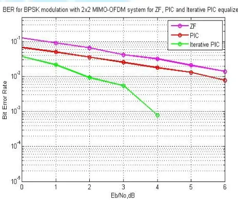
Fig .5. Performance comparison of ZF, MMSE, PIC and Iterative PIC equalizers in 2x2 MIMO-OFDM system .
From the plot it is clear that 2x2 MIMO-OFDM system with Iterative PIC equalizers for case of pure equalization compared ZF, MMSE, and PIC equalizer. The code BER of proposed scheme Iterative PIC is produced after iteration. when iteration increases the BER is significantly improved. From simulation results the proposed scheme is quite effective in all simulation configurations. However, Iterative PIC detection scheme is better in the diversity gain and when the intefrence comes from the other layers is completely cancelled. Modulation scheme employed here is BPSK.
V. CONCLUSION
The combination of MIMO-OFDM systems are used to improve the spectrum efficiency of wireless link reliability in wireless communication systems. Iterative PIC scheme for MIMO OFDM systems transmission including the feasibility of using the priori information of the transmit sequence of MMSE compensation. Performance of Iterative PIC detection technique is better compared to ZF, MMSE, PIC using BPSK
modulation scheme in high interference environment. The simulation result shows that the performance of proposed scheme is greatly improved compared to other detection receivers for MIMO-OFDM systems.
VI. FUTURE SCOPE
Any type of modulation techniques such as QPSK or QAM will integrate the channel encoding part.
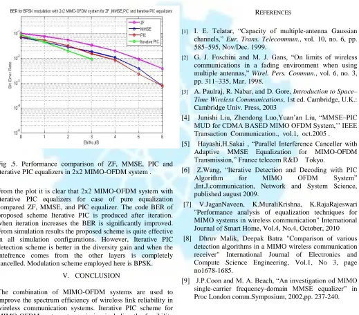
REFERENCES
[1] I. E. Telatar, “Capacity of multiple-antenna Gaussian
channels,” Eur. Trans. Telecommun., vol. 10, no. 6, pp.
585–595, Nov/Dec. 1999.
[2] G. J. Foschini and M. J. Gans, “On limits of wireless
communications in a fading environment when using
multiple antennas,” Wirel. Pers. Commun., vol. 6, no. 3,
pp. 311–335, Mar. 1998.
[3] A. Paulraj, R. Nabar, and D. Gore, Introduction to Space–
Time Wireless Communications, 1st ed. Cambridge, U.K.: Cambridge Univ. Press, 2003
[4] Junishi Liu, Zhendong Luo,Yuan’an Liu, “MMSE–PIC
MUD for CDMA BASED MIMO OFDM System,’’ IEEE
Transaction Communication., vol.1, oct.2005 .
[5] Hayashi,H.Sakai , “Parallel Interference Canceller with Adaptive MMSE Equalization for MIMO-OFDM
Transmission,” France telecom R&D Tokyo.
[6] Z.Wang, “Iterative Detection and Decoding with PIC
Algorithm for MIMO OFDM System”
,Int.J.communication, Network and System Science, published august 2009.
[7] V.JaganNaveen, K.MuraliKrishna, K.RajaRajeswari "Performance analysis of equalization techniques for MIMO systems in wireless communication" International Journal of Smart Home, Vol.4, No.4, October, 2010 [8] Dhruv Malik, Deepak Batra "Comparison of various
detection algorithms in a MIMO wireless communication receiver" International Journal of Electronics and Compute Science Engineering, Vol.1, No 3, page no1678-1685.
[9] J.P.Coon and M. A. Beach, “An investigation od MIMO
single-carrier frequency-domain MMSE equalizer” in
[image:7.612.38.557.187.643.2]