Soil Structure Interaction of Multi-Storied Building
With and Without Infill Wall
P.V.Manekar1, L. R. Wankhade2
1, 2
Applied Mechanics, Govt. College of Engg., Amravati (India)
Abstract: Masonry infill’s are normally considered as non-structural elements and their stiffness contributions are generally ignored in practice, such an approach can lead to an unsafe design. The masonry infill walls though constructed as secondary elements behaves as a constituent part of the structural system and determine the overall behavior of the structure especially when it is subjected to seismic loads. In this paper seismic analysis has been performed using equivalent lateral force method for different reinforced concrete (rc) frame building models that include bare frame, in filled frame and open first storey frame. The results of bare frame, in filled frame and open first storey frame are discussed and conclusions are made. In modeling the masonry infill panels the equivalent diagonal strut method is used and the software etabs is used for the analysis of all the frame models.
Keywords: soil structure interaction, infill wall, bare frame, etabs, th
I. INTRODUCTION
There is growing responsiveness of multi-storey reinforced concrete structures, to accommodate growing population. Generally such structures have prismatic sections which are common in developing countries. Reinforced concrete frame buildings with masonry infill walls have been widely constructed for commercial, industrial and multi storey residential uses in seismic regions. Masonry infill typically consists of bricks or concrete blocks constructed between beams and columns of a reinforced concrete frame. The masonry infill panels are generally not considered in the design process and treated as architectural (non-structural) components. Nevertheless, the presence of masonry infill walls has a significant impact on the seismic response of a reinforced concrete frame building, increasing structural strength and stiffness. Infill wall alters the stiffness, strength and ductility of the RC moment resisting frame. Due to this, it becomes necessary to understand the behavior of the infill wall in terms of these three parameters. The effect of infill walls on the RC frames is well noted in many earthquake scenarios from the past. Comparatively, less damage was observed for RC frames with masonry infill walls when subjected to earthquakes.
A. Infill Wall
Reinforced concrete frame buildings with masonry infill walls have been widely constructed for commercial, industrial and multi storey residential uses in seismic regions. Masonry infill typically consists of bricks or concrete blocks constructed between beams and columns of a reinforced concrete frame. The masonry infill panels are generally not considered in the design process and treated as architectural (non-structural) components. Nevertheless, the presence of masonry infill walls has a significant impact on the seismic response of a reinforced concrete frame building, increasing structural strength and stiffness. Properly designed infills can increase the overall strength, lateral resistance and energy dissipation of the structure [1]
B. Soil Structure Interaction
The interaction among the structure, foundation and soil medium below the foundation alter the actual behavior of the structure considerably as obtained by the consideration of the structure alone. Flexibility of soil medium below foundation decreases the overall stiffness of the building frames resulting in an increase in the natural period of the system. Soil-Structure Interaction (SSI) is a collection of phenomena in the response of structures caused by the flexibility of the foundation soils. Analytic and numerical models for dynamic analysis typically ignore SSI effects of the coupled in nature structure-foundation-soil system. It has been recognized that SSI effects may have a significant impact especially in cases involving heavier structures and soft soil conditions.
II. SOFTWARE USED FOR PROJECT
a sophisticated assessment of seismic performance, modal and direct-integration time-history analyses may couple with P-Delta and Large Displacement effects. Nonlinear links and concentrated PMM or fiber hinges may capture material nonlinearity under monotonic or hysteretic behavior.
III. ELASTIC CONSTANTS USED FOR SOIL/ MATERIAL BELOW FOUNDATION
[image:3.612.73.538.217.428.2]Dynamic analysis of the structure and its interaction with the material (foundation soil) under the structure affects the response of structure. The interaction between foundation and soil depends on the elastic properties of foundation soil and foundation dimensions. The foundation flexibility in the analysis is considered by means of replacing the foundation by statically equivalent springs. [2]
Table 3.5.1: Spring Constant and Radius of Equivalent Springs Spring Constant Equivalent Radius
)
8
7
(
)
1
(
32
0
K
GR
K
X Y
f
A
R
0
)
1
(
4
0
GR
K
z
fA
R
0
)
1
(
3
8
03
GR
KR
X 0 44
f
I
R
y)
1
(
3
8
03
GR
KR
Y 0 44
f
I
R
x3
16
GR
03KR
Z
40
)
(
2
f
I
f
I
R
x
y [image:3.612.71.540.220.428.2]Where, G is shear modulus of soil, ν is the Poisson’s ratio of soil and Ro is the equivalent radius; Af is the area of the footing and Ixf and Iyf are moments of inertia of the footing about X and Y axis, respectively. The values of Poisson’s ratio (ν) and shear modulus (G) for three different kinds of soil, hard, medium and soft are given as follows. The elastic properties of foundation soil for hard, medium and soft soil are tabulated in Table 3.5.2
Table 3.5.2 Elastic Properties of Foundation Soil [3] Type of soil
Mass Density (kN/m3) Shear Wave Velocity (m/sec)
Poisson’s Ratio ν
Hard 21 21 0.15
Medium 18.5 18.5 0.33
Soft 17 17 0.48
Table 3.5.3: Spring Constants for Different Soil Used In Foundation Soil type Kx
(kN/m) Ky (kN/m) Kz (kN/m) KRx (kN/rad) KRy (kN/rad) KRz (kN/rad) stiff 43545.98 87424.22 45009.56 11938.95 9779.03 7302.94
medium 28965.48 64082.71 29881.34 14071.64 10290.82 7242.058
soft 15455.81 40345.59 15885.57 14573.27 8790.86 7977.642
[image:3.612.75.539.516.700.2]Table 3.5.4: Spring Constants for Different Soil Used In Foundation Soil type Kx
(kN/m) Ky (kN/m) Kz (kN/m) KRx (kN/rad) KRy (kN/rad) KRz (kN/rad) stiff 53670.59 110934.7 54481.7 25639.75 24845.51 11193.18 medium 37872.5 83792.89 39000.6 30991.79 22210.34 19023.39 soft 19156.7 48899.44 19696.77 26713.93 15444.361 17612.18
The numerical values of spring constants for different type of foundation soil for mat footing of g+9 building are summarized in Table 3.5.5.
Table 3.5.5: Spring Constants for Different Soil Used In Foundation Soil type Kx
(kN/m) Ky (kN/m) Kz (kN/m) KRx (kN/rad) KRy (kN/rad) KRz (kN/rad) stiff 48946.17 102252.2 48964.17 19352.9 23813.18 7213.64 medium 26810.82 58735.18 26810.82 14531.36 13863.41 9097.835
Soft 11391.32 29235.56 11391.32 7601.43 5482.19 5914.376
For determining the seismic performance of soil structure interaction of 3 storey,6 storey and 11 storey building resting on flat ground with two different building configuration i.e. by considering infill and without infill are considered and models are analyzed viz building on hard soil, medium soil, soft soil, and building with fixed supported base.
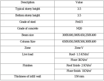
IV. STRUCTURAL ELEMENT SIZES AND LOADING 24 models are considered for the analysis. The description is given as follows
Table 3.8.1: Description of Building Models
Description Value
Typical storey height 3.5
Bottom storey height 3.5
Grade of steel Fe415
Grade of concrete M20
Beam size 300X600,300X450,250X400
Column Size 650X650,500X500,300X400
Zone Zone V
Live load Roof- 1.5 KN/m2
Floor-3KN/m2
Finishes Roof finish- 2 KN/m2
Floor finish- 1KN/m2
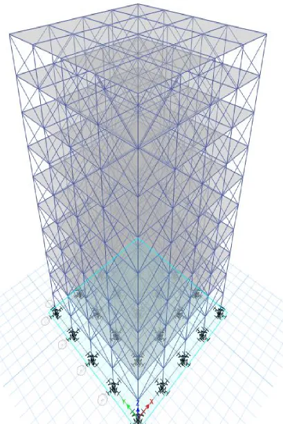
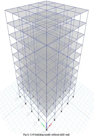
[image:4.612.126.486.401.682.2]Fig 4: G+9 building model without infill wall
V. METHODOLOGY
[image:6.612.125.493.92.624.2]VI. RESULTS AND DISCUSSION
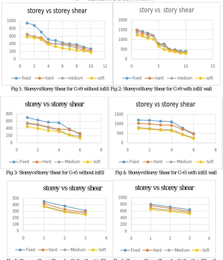
Fig 1: StoreyvsStorey Shear for G+9 without infill Fig 2: StoreyvsStorey Shear for G+9 with infill wall
Fig 3: StoreyvsStorey Shear for G+5 without infill Fig 4: StoreyvsStorey Shear for G+5 with infill wall
Fig 5: Storeyvs Storey Shear for G+2 without infill Fig 6: Storeyvs Storey Shear for G+2 with infill wall
VII. CONCLUSIONS AND REMARKS
A. Storey shear increases in infill wall model as compare to bare frame model.
B. Storey shear is maximum in fixed soil type model as compare to hard, medium and soft
C. Storey shear is maximum in soft soil type model as compare to hard, medium and fixed
D. The presence of infill wall can affect the seismic behavior of frame structure to large extent, and the infill wall increases the strength of the structure.
E. Story Shear in infill wall containing building is approx. 35% more as compared to building without infill wall. 0 200 400 600 800 1000
0 2 4 6 8 10 12
storey vs storey shear
fixed hard medium soft
0 500 1000 1500 2000
0 5 10 15
story vs story shear
fixed hard medium soft
0 200 400 600 800
0 2 4 6 8
storey vs storey shear
Fixed Hard Medium Soft
0 500 1000 1500
0 2 4 6 8
storey vs storey shear
Fixed Hard Medium Soft
0 100 200 300 400 500
0 1 2 3 4
storey vs storey shear
Fixed Hard Medium Soft
0 200 400 600 800 1000
0 1 2 3 4
storey vs storey shear
REFERENCES
[1]. Dr. B S Munjal,et.al. “Seismic Performance Assessment of the Reinforced Concrete Structure with Masonry Infill wall” Volume 3, 2015 [2]Wakchaure M.R, “Earthquake Analysis of High Rise Building with and Without In filled Walls” Volume 2, August 2012
[3] Amar R Chougule et.al. “Seismic Soil Structure Interaction of Buildings with Rigid and Flexible Foundation”, (2013) [4] FEMA 356, Seismic rehabilitation prestandard
![Table 3.5.2 Elastic Properties of Foundation Soil [3] Shear Wave Velocity](https://thumb-us.123doks.com/thumbv2/123dok_us/8302703.854964/3.612.71.540.220.428/table-elastic-properties-foundation-soil-shear-wave-velocity.webp)