2010
©IJRASET (UGC Approved Journal): All Rights are ReservedFully Stressed Design of Pratt Truss using STAAD.
Pro Software
Chandresh Kumar Jha1, M. C. Paliwal2
1,2Department of Civil & Environmental Engineering, NITTTR Bhopal
Abstract: This paper presents the investigation of optimization of Pratt Truss by Fully Stressed Design (FSD) technique utilizing STAAD. Pro software version STAAD. Pro V8i (SELECT series4). Three span ranges of the trusses i.e. 8m, 10m and 12m have been considered and each truss has been subjected to 24 sorts of load cases by changing nodal load locations but load applied will always be symmetric. The four arrangements of load condition are taken, i.e., 100 kN, 125 kN, 150 kN and 175 kN. The total 72 number of trusses have been optimized in this study to achieve a target stress of 100 MPa. The optimal mass of all the trusses for each case and maximum deflection for each case have been calculated. Further deflection per unit mass have also been calculated and compared for each span with graph. Results of the study will be helpful in the designing of a truss that must fulfill the requirement of economy as well as strength.
Keywords: Pratt Truss, STAAD, Fully Stressed Design, Optimization, Load cases.
I. INTRODUCTION
The resources are depleting day by day in present time and also the cost is increasing of material as well as labor cost is also increasing. As per the popular concept of present time in building construction i.e. the concept of green building we must conserve resources for the betterment of society in all aspect and for this the term optimal structure is widely used. Optimization of the structure can be done in various aspects which are known as objectives which could be weight, volume, cost or stiffness of the structure. By using optimization technique cost as well as material to be used in structure is saved. Optimality of the structure can be defined in terms of weight, volume, cost, stiffness etc. Some constraints are used for optimization. Some structures that lie within the constraints are generaally known as feasible solutions to the optimization problem. There are numerous makes an attempt has been created for the optimization of truss structures. These optimizations were supported (based on) size, shape and topology factors. So as to urge the truss optimized the cross sectional area of each member of truss are modified. It reduces the weight of structure and what is more the overall cost of the structure as well and hence Light weight structures are made instead of traditional heavy weight structures. Traditionally the structural optimization techniques includes; mathematical programming, optimality criteria, method of approximation and fully stressed design and fully utilized design. In past as well as recently many researchers had been carried out research on optimization of truss.
Kavya Rao M. N., K. N. Vishwanath (2014) Presented a paper on Design Optimization of an Industrial Structure from steel frame to pre-engineered building in which analysis is done using STAAD.Pro software which is the new concept of single storey building construction which includes the technique of providing the best possible section according to the optimum requirement and this paper gives a comparative study of the pre-engineered building concept and conventional steel building concept which is achieved by designing an industrial building using both the concepts and analyzing them using the structural analysis and design software STAAD.Pro(1). S. Ganzerli (2013) presented a paper on Direct Fully Stressed Design for Displacement Constraints in which anew fully stressed design method for the solution of the general weight optimization problem applicable to determinate trusses subject to displacement constraints is presented.
2011
©IJRASET (UGC Approved Journal): All Rights are Reserveddisplacement constraints is attained and the results had been compared favorably with those solved with other well known optimization techniques as, for example, genetic algorithms (2).
Fatih Mehmet Özkal and Habib Uysal (2010) presented a paper on Fully Stressed Design method to determine the optimum strut and tie-model for beam-column connections as per this paper topology optimization and strut and tie-model methods got remarkable success and a performance index formulation assists the selection of the optimum design from the process by considering the fully stressed design concept also evolutionary structural optimization (ESO) is done as well as shape optimization criteria are stress, strain energy, displacement, etc are taken and a new performance index formulation, which issued to select the optimum design from the optimization process by considering the fully stressed design concept as the most affective criterion and deals with the previously mentioned problem by reviewing earlier studies at length the efficiency and capability of the new index are demonstrated by several design examples (3). Wang Ren-hua, Zhao Xian-zhong, Xie Buying(2009) has presented a paper on the topic Structural Topology and Shape Annealing (STSA), as a heuristic mathematic algorithm, achieves the real topology optimization of truss structures but little considering the mechanical characters of structure in which the Fully stressed design (FSD) criteria are good at sizing optimization of the fixed configuration structures and also the paper has aim to apply the mechanical algorithm to guide the heuristic search process of STSA and establish a new hybrid algorithm for the truss optimization which is the matter of research now-a-days the results give the indication that the novel algorithm is meaningful and also better than the solo shape annealing algorithm for the topology optimization of truss structure subjected to stress constraint as well as Euler buckling constraints (4). In this study, Fully Stressed Design method has been utilized for optimization of Pratt Trusses by using STAAD.Pro V8i (SELECT series 4) software. For this, 24 different load cases have been considered for three different spans. Load applied was always symmetric throughout the analysis. So by the combination of load and spans, the total 72 cases have been analyzed and steel mass, deflection and deflection per unit mass are calculated. The section used in this study is circular section.
II. FULLYSTRESSEDDESIGN
In this method it is assumed that each area carries a constant force, dependent only on the external load which means the internal force of one member is supposed not to affect the force in the other members.
A re-sizing technique is used by assuming that Fi i.e. the internal force in the ith member, is constant and Fi can be expressed by
stress (σi) times the cross-sectional area (Ai) and further this leads to the subsequent formulation and the formulas used in Fully
Stressed Design are –
Fi = σi,new Ai,new = σi,old Ai,old --- (i)
Ai, new = Ai, old σi, old / σi,o --- (ii) This is an iterative technique and it is in huge practice nowadays.
We all know that whenever load is applied on a truss structure, stress occurs in each member of truss and all the members have different stresses but fully stressed design mean stress in each member should be equal and to achieve this purpose area of cross section is changed either increased or decreased. As our basic purpose is to maintain a same stress in each member of the truss after application of the load and we also know that stress is inversely proportional to area of cross section so if we reduce the area of cross section of any member, stress gets increase in the member and vice versa. So by increasing the area of cross section of any member, stress gets reduced and vice versa. After several iterations we can get same stress in all the member of truss as we required.
Stress = Force / Area --- (iii)
We take Pratt truss of three different spans i.e. 8m, 10m and 12m with 2m height and analyzed them for 24 different load cases. In this way the total numbers of the trusses to be analyzed are 72. Firstly we take a constant stress and after the application of loads stresses are produced in each member of the truss.
III.STRUCTURALMODELLINGANDANALYSIS
2012
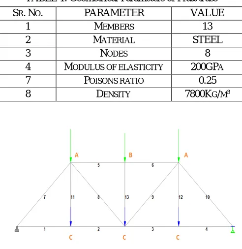
©IJRASET (UGC Approved Journal): All Rights are ReservedTABLE 1. Geometrical Parameters of Pratt truss
[image:4.612.106.501.345.709.2]
Fig. 1. Modelling of Pratt Truss
TABLE 2. Properties of Pratt Truss SR.
NO. PARAMETER
FOR 8M SPAN
FOR 10M SPAN
FOR 12M SPAN
1 LENGTH OF BOTTOM CHORD
MEMBERS 2M
2.5M 3M
2 LENGTH OF TOP CHORD MEMBERS 2M 2.5M 3M
3 LENGTH OF INCLINED MEMBERS 2.83M 3.2M 3.61M
4 HEIGHT 2M 2M 2M
TABLE 1. Load Cases
SR.NO. PARAMETER VALUE
1 MEMBERS 13
2 MATERIAL STEEL
3 NODES 8
4 MODULUS OF ELASTICITY 200GPA
7 POISONS RATIO 0.25
8 DENSITY 7800KG/M³
SR.NO. LOADA(KN) LOADB(KN) LOADC(KN)
1 100 125 150
2 100 150 125
3 100 125 175
4 100 175 125
5 100 150 175
6 100 175 150
7 125 100 150
8 125 150 100
9 125 150 175
10 125 175 150
11 125 100 175
12 125 175 100
13 150 100 125
2013
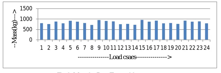
©IJRASET (UGC Approved Journal): All Rights are ReservedFSD has been carried out in iterative manner to the target stress of 100 MPa and cross-sectional areas of the members were noted down. Since the density of steel was known the steel i.e. 7800 kg/m3, mass of steel has been calculated for the overall truss structure. Circular section has been used for analysis in this study and diameter of each member each is considered to be different as per need. Optimal mass of the Pratt trusses of three different spans i.e., 8m, 10m and 12m has been calculated for all 24 load cases and compared.
It is observed that, the Optimal Maximum and Minimum Mass of Pratt Truss of 8m span with 2m height are Maximum Mass of truss = 955.715 Kg at LOAD CASE 15
Minimum Mass of truss = 717.764 Kg at LOAD CASE 8
Hence Maximum and Minimum Mass occurs at Load Case 15 and Load Case 8 respectively.
0 500 1000 1500
1 2 3 4 5 6 7 8 9 10 11 12 13 14 15 16 17 18 19 20 21 22 23 24
--M
a
ss
(k
g
)-
-->
---Load csaes--->
Fig 2. Mass for Pratt Truss of 8m span
It is observed that, the Optimal Maximum and Minimum Mass of Pratt Truss of 10m span and 2m height are Maximum Mass of truss = 1341.357 Kg at LOAD CASE 15
Minimum Mass of truss = 1006.989 Kg at LOAD CASE 8
Hence Maximum and Minimum Mass occurs at Load Case 15 and Load Case 8 respectively.
0 500 1000 1500
1 2 3 4 5 6 7 8 9 10 11 12 13 14 15 16 17 18 19 20 21 22 23 24
--M
a
ss
(kg)
-->
---
Load csaes---->
Fig 3. Mass for Pratt Truss of 10m span
15 150 125 175
16 150 175 125
17 150 100 175
18 150 175 100
19 175 100 125
20 175 125 100
21 175 125 150
22 175 150 125
23 175 100 150
[image:5.612.171.443.90.232.2] [image:5.612.137.494.378.496.2]2014
©IJRASET (UGC Approved Journal): All Rights are ReservedIt is observed that, Optimal Maximum and Minimum Mass of Pratt Truss of 12m span and 2m height are Maximum Mass of truss = 1557.938 Kg at LOAD CASE 15
Minimum Mass of truss = 1169.449 Kg at LOAD CASE 8
Hence Maximum and Minimum Mass occurs at Load Case 15 and Load Case 8 respectively.
0 500 1000 1500 2000
1 2 3 4 5 6 7 8 9 10 11 12 13 14 15 16 17 18 19 20 21 22 23 24
----M a ss (k g) ---> ---Load csaes--->
Fig 4. Mass for Pratt Truss of 12m span
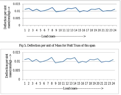
And after finding optimal mass we calculate the maximum deflection of the trusses and it is observed that the maximum deflection of truss is
For 8m span = 8.995 mm occurs at central node of top of the truss. For 10m span = 12.317 mm occurs at central node of top of the truss. For 12m span = 16.361 mm occurs at central node of top of the truss.
Then we calculate the value of deflection per unit of mass for all spans and draw the graph for each span as below:
0 0.005 0.01 0.015
1 2 3 4 5 6 7 8 9 10 11 12 13 14 15 16 17 18 19 20 21 22 23 24
D ef le ct io n pe r ui n t m a ss (m m /kg) ---> ---Load csaes--->
Fig 5. Deflection per unit of Mass for Pratt Truss of 8m span
0 0.005 0.01 0.015
1 2 3 4 5 6 7 8 9 10 11 12 13 14 15 16 17 18 19 20 21 22 23 24
D e fl e c ti o n p e r u in t m as s( m m /k g )- --> ---Load csaes--->
[image:6.612.139.493.145.305.2] [image:6.612.124.511.406.708.2]2015
©IJRASET (UGC Approved Journal): All Rights are Reserved0 0.005 0.01 0.015
1 2 3 4 5 6 7 8 9 101112 131415 16171819 202122 2324
D
ef
le
ct
io
n
pe
r
ui
n
t
m
a
ss
(m
m
/kg)
-->
---Load csaes--->
Fig 7. Deflection per unit of Mass for Pratt Truss of 12m span
Comparison between the optimal mass of truss of three different spans for 24 load cases have been shown in the graph given below:
0 500 1000 1500 2000
1 2 3 4 5 6 7 8 9 10 11 12 13 14 15 16 17 18 19 20 21 22 23 24
---M
a
ss
(k
g
)-
-->
---Loa d cases--->
8m Sapn
10m span
12m Span
Fig 8. Optimal Mass and load graph of truss showing comparison between mass of three different spans
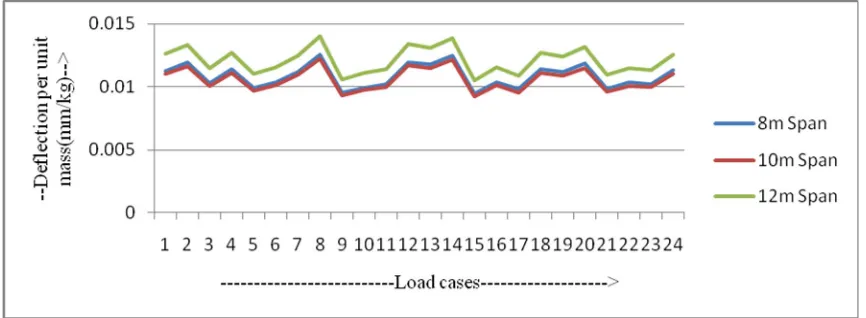
Comparison between the graphs for the deflections per unit of optimal mass of trusses of three different spans having 24 load cases have been shown in the graph given below:
Fig 2. Deflection per unit Mass and load graph of truss showing comparison between the three different spans
IV.CONCLUSIONS
In this study, Fully Stressed Design of Pratt Trusses have been carried out by using STAAD.Pro V8i (SELECT series 4) software for three different spans and 24 different load cases. The objective of this analysis is to determine the steel mass and the central deflection of each truss. The following conclusions can be drawn from Figure 8:
[image:7.612.138.492.95.219.2] [image:7.612.100.527.259.397.2] [image:7.612.100.533.450.609.2]2016
©IJRASET (UGC Approved Journal): All Rights are Reservedeven with in the span there is some variation. As observed from the study the optimal mass for the load case 8 (i.e. 125/150/100) is 717.764 Kg and the same for the case 15 150/125/175 is 955.715 kg , so there is significant variation in the steel mass.
For 10 m span Pratt Truss having a rise of 2 m, it is seen that variation is more than 8m span in the steel mass. For 12 m span Pratt Truss having a rise of 2 m, it is seen that variation is more than 8m & 10m span in the steel mass. Since it is the biggest span in comparison to the other two, the overall steel mass will be more.
It is concluded that weight always increase with increase in the span or height. Hence, it is necessary for design engineer to optimize the structure to have the best height and span combination to save the material and make the structure economical. The following conclusions can be drawn out of the above graph in Figure 10:
The pattern of variation of graph for the deflection per unit of mass is same for all the three spans.
As the span increases the deflection per unit of also increases and the increment is rapidly growing with span.
V. ACKNOWLEDGMENT
I take this opportunity to express my cordial gratitude & deep sense of in debtedness to all the faculty members of NITTTR Bhopal who gave me proper guidance in this paper and I also would like to thanks my friend Love, Pandit, Rakshit, and all other friends.
REFERENCES
[1] Design Optimisation of an Industrial Structure from Steel Frame to Pre-Engineered Building. Kavya.Rao.M.N, K.N.Vishwanath. 2014, International Journal of
Research in Advent Technology, pp. 6-10.
[2] Direct Fully Stressed Design for Displacement Constraints. Ganzerli, S. 2013, 10th World Congress on Structural and Multidisciplinary Optimization, pp. 1-5.
[3] A FULLY STRESSED DESIGN METHOD TO DETERMINE THE OPTIMUM STRUT-AND-TIE MODEL FOR BEAM–COLUMN CONNECTIONS.
Uysal, Fatih Mehmet Özkal and Habib. 2012, International Journal of Computational Methods, pp. 1-15.