Design and Analysis of Distributed Embedded Systems
using AADL - Application to the Precision Time
Protocol
Mohamed Yassin Chkouri
National School of Applied Sciences
2222 M hannech II
93 000 Tetouan - Morocco
Marius Bozga
Verimag, Centre Equation
2, avenue de Vignate
38610 GIERES - France
ABSTRACT
Prototyping distributed embedded system can be seen as a collec-tion of many requirements covering many domains. System de-signers and developers need to describe both functional and non-functional requirements. Building distributed systems is a very te-dious task since the application has to be verifiable and analyzable. Architecture Analysis and Design Language (AADL) provides ad-equate syntax and semantics to express and support distributed em-bedded systems.
This paper studies a general methodology for translating AADL thread component depending on the thread implementation into the BIP (Behavior Interaction Priority) language and for prototyping distributed applications using the Precision Time Protocol (PTP) for building and translating AADL systems into a distributed appli-cation using network communiappli-cation protocol. This allows simula-tion of systems specified in AADL to fully assess system viability, to refine and to correct the behavior of the system using the BIP (Behavior Interaction Priority) toolset.
Keywords:
Architecture Analysis and Design Language, Modeling, Dis-tributed Embedded System, Model Transformation, Simulation, Validation
1. INTRODUCTION
Building distributed embedded systems requires a stringent methodology and involves many tightly coupled steps, from early requirements capture (number of tasks, their interactions, non-functional attributes) to validation (feasibility of scheduling) down to implementation and testing. Prototyping distributed applications can be extremely useful in evaluating a design, and also in under-standing the effect of different parameters on the performance of an application.
Designing distributed systems is an extremely complex task and demands more attention and rigorous methodology. The produced distributed systems have to conform to many stringent functional and non-functional requirements from multiple contexts such as
space, avionics, etc. Ensuring all requirements and features be-comes very hard if the whole system is hand-coded. Thus, the ap-plication code should preferably be generated automatically from a verifiable and analyzable model. This facilitates the work of devel-opers, helps during the stage of code verification and speed up the development cycle. Besides, constructing a verifiable model from the application model using model transformation is simpler and safer than constructing this model from source code.
Architecture Description Languages (ADLs) have been proposed to support the development process of embedded real-time and dis-tributed applications. Among the ADLs, AADL [2] is the Archi-tecture Analysis and Design Language that allows the modeling of distributed, real-time and embedded systems. AADL was first in-troduced to model the software and hardware architectures in the avionics domain. AADL can be seen as a collection of many re-quirements covering many domains. System designers and devel-opers need to describe both functional and non-functional require-ments. These requirements must then be sorted and enforced at the deployment level. We will present the set of requirements that must be respected to build distributed systems.
We have shown in previous work [13, 12], how AADL systems can be automatically translated into BIP [6] (Behavior Interaction Pri-ority), and analyzed using the BIP toolset. BIP is a language for the description and composition of components as well as asso-ciated tools for analyzing models and generating code on a dedi-cated middleware. The language provides a powerful mechanism for structuring interactions involving rendezvous and broadcast. The model construction methodology applied to AADL models opens the way for enhanced analysis and early error detection by using BIP verification techniques. Once the model has been gen-erated, three model checking techniques for verification can be ap-plied: Model checking by Aldebaran [9], model checking with ob-server and D-Finder tool [8].
and network communication protocol. We begin with a model built by the application designer, who maps its application entities onto a hardware architecture. Then, we use AADL into BIP tool to gen-erate BIP model conforming to AADL semantics. Finally, we use a code generator to generate an executable model for each system with communication protocol.
To illustrate the translation from distributed AADL systems into BIP, we use Precision Time Protocol (PTP) as a case study. Based on our experience, we use the AADL to model PTP and its transla-tion into BIP. This translatransla-tion allows the simulatransla-tion of distributed systems and the application of formal verification techniques, e.g., verification of properties, deadlock detection, etc. Using our tool, we were able to run, to debug and evaluate the case study in a na-tive platform (PC) before deploying it on a distributed embedded platform.
Code generation of distributed embedded applications from models is not limited to AADL. In fact, distributed and high-integrity sys-tems are probably the domain which has the most maturity. OCA-RINA [15] allows model manipulation, generation of formal mod-els to perform scheduling analysis and generate distributed applica-tions. OCARINA allows code generation from AADL descriptions to Ada. PolyORB [18] is a middleware toolset that provides distri-bution services through standard programming interfaces and com-munication protocols. However, the generated code from AADL does not take into account the annex behavior specifications [1]. This paper is organized as follows. Section 2 gives an overview of AADL. In Section 3, we explain the translation of the thread com-ponent depending on four cases and how to translate AADL sys-tems into a distributed application using network communication protocol. In Section 4, we present a PTP case study and its deploy-ment into a distributed application. Conclusions close the article in Section 5.
2. OVERVIEW OF AADL 2.1 Generalities
The SAE Architecture Analysis & Design Language (AADL) [2] is a textual and graphical language used to design and analyze the software and hardware architecture of performance-critical real-time systems. It plays a central role in several projects such as Top-cased [4], OSATE [3], etc.
A system modeled in AADL consists of application software mapped to an execution platform. Data, subprograms, threads, and processes collectively represent application software. They are calledsoftware components. Processor, memory, bus, and device collectively represent the execution platform. They are called exe-cution platform components. Execution platform components sup-port the execution of threads, the storage of data and code, and the communication between threads. Systems are called composi-tional components. They permit software and execution platform components to be organized into hierarchical structures with well-defined interfaces. Operating systems may be represented either as properties of the execution platform or can be modeled as software components.
2.2 AADL Components
2.2.1 Software Components. AADL has the following categories of software components: subprogram, data, thread and process. Asubprogramcomponent represents an execution entry-point in the source text. Subprograms can be called from threads and from other subprograms. These calls are handled sequentially by the threads. Thedatacomponent type represents a data type in the
source text that defines a representation and interpretation for in-stances of data. Athreadrepresents a sequential flow of control that executes instructions within a binary image produced from source text. A thread always executes within a process. A scheduler man-ages the execution of a thread. Aprocessrepresents a virtual ad-dress space. Process components are an abstraction of software re-sponsible for executing threads.
2.2.2 Hardware Components. Execution platform components represent hardware and software that is capable of scheduling threads, interfacing with an external environment, and performing communication for application system connections.
AADLprocessorcomponents are an abstraction of hardware and software that is responsible for scheduling and executing threads. In other words, a processor may include functionality provided by op-erating systems. Adevicecomponent represents an execution plat-form component that interfaces with the external environment. A device can interact with application software components through their ports. Abuscomponents are used to describe all kinds of net-works, buses, etc. AMemorycomponents are used to represent any storage device: RAM, hard disk, etc.
2.2.3 Systems Component. A system is the toplevel component of the AADL hierarchy of components. A system component rep-resents a composite component as an assembly of software and ex-ecution platform components. All subcomponents of a system are considered to be contained in that system.
2.3 Connections
Aconnectionis a linkage that represents communication of data and control between components. This can be the transmission of control and data between ports of different threads or between threads and processor or device components. We gave more details about the connection types and how to translated into BIP in previ-ous work [11].
2.4 Annex Behavior Specification
Behavior specifications [1] can be attached to AADL model ele-ments using an annex. The behavioral annex describes a transition system attached to subprograms and threads. Behavioral specifica-tions are defined by the following elements:
—State variablessection declares typed identifiers. They must be initialized in theinitializationsection.
—Statessection declares automaton states.
—Transitionssection defines transitions from a source state to a destination state. The transition can be guarded with events or boolean conditions. An action part can be attached to a transition.
3. FROM AADL TO DISTRIBUTED IMPLEMENTATION USING BIP 3.1 The BIP Component Framework
Fig. 1. Generation of the BIP application
BIP models and ensure that they meet properties such as deadlock-freedom, state invariants and schedulability. The BIP language al-lows hierarchical construction [14] of composite components from atomic ones by using connectors and priorities. Several case studies were carried out such as an MPEG4 encoder [17], TinyOS [7], and DALA [5].
3.2 Transformation from AADL to BIP
The AADL models are transformed into BIP automatically by us-ing our AADL to BIP translation tool described in [12, 13]. Fig-ure 1 shows the generation of an application from an AADL de-scription that consists of translating AADL constructions by adding the behavior descriptions to BIP.
The model construction methodology applied to AADL models opens the way for enhanced analysis and early error detection by using BIP verification techniques. Once the model has been gen-erated, three model checking techniques for verification can be ap-plied:
3.2.1 D-Finder. is an interactive tool for checking deadlock-freedom for component-based systems by using a static analysis method. It takes as input BIP programs and applies proof strate-gies to eliminate potential deadlocks by computing increasingly stronger deadlocks.
3.2.2 Model checking by Aldebaran. The second technique of verification is model-checking by using the tool Aldebaran [9]. Ex-haustive exploration by the BIP exploration engine generates a La-beled Transition System (LTS) which can be analyzed by model checking. For example, Aldebaran takes as input the LTS gener-ated from BIP and checks for deadlock-freedom and other temporal properties.
3.2.3 Model checking with observers. The third technique of ver-ification is by using BIP observers to express and check require-ments. Observers allow us to express in a much simple manner most safety requirements. We apply this technique to verify some properties as verification of communication, and verification of thread deadline.
[image:3.612.58.288.65.232.2]3.2.4 Simulation & Debugging. In addition to the verification, we can simulate or test prototype implementations by creating an executable system. We can use an interactive simulation and de-bugger to verify each interaction step by step and to know which
Fig. 2. BIP model for thread behavior
state or port is activated. These analysis allow to fully assess system viability, to refine and to correct the behavior of the system.
3.2.5 Code generator. The code generator takes as input a model, generated by the parser, and transforms it to a C++ appli-cation code. The appliappli-cation is an executable model of the original BIP program. Code is generated for each atomic component, con-nectors and priorities, i.e., the code is modular and preserves the structure of the initial model.
3.3 Translation of Thread Component into BIP
In this paper we present the translation of thread component that represents the principal component in the AADL architecture into BIP. This translation is the result of our study about this component. To have a complete translation of the thread component and to be able to use threads in larger domains, we must take into account four main cases of the threads implementation :
(1) without the implementation ;
(2) contains a sequence of subprograms calls ; (3) contains annex behavior specification ;
(4) reference to a C/C++ file containing the behavior description.
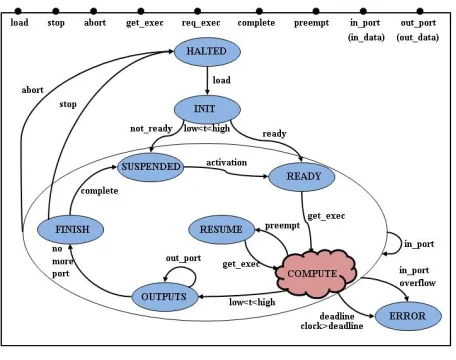
The aim of this study about the thread behavior is to define general rules concerning the BIP code generation from AADL descriptions and the implementation of descriptions provided by the user. An AADL thread is modelled in BIP by an atomic component as shown in Figure 2. The initial state of the thread isHALTED. On an interaction through portloadthe thread is initialized. Once initial-ization is completed the thread enters theREADYstate, if the thread is ready for an interaction through the portreq exec. Otherwise, it enters theSUSPENDEDstate. When the thread is in theSUSPENDED
state it cannot be dispatched for execution.
When in theSUSPENDEDstate, the thread is waiting for an event and/or period to be activated depending on the thread dispatch pro-tocol (periodic, aperiodic, sporadic). In theREADYstate, a thread is waiting to be dispatched through an interaction in the portget exec. When dispatched, it enters the stateCOMPUTEto make a compu-tation. Upon successful completion of the computation, the thread goes to theOUTPUTSstate. If there are someout portsto dispatch the thread returns to the OUTPUTSstate. otherwise, it enters the
Fig. 3. Function call for the external file
The thread may be requested to enter itsHALTEDstate through a portstop after completing the execution of a dispatch. A thread may also enter the threadHALTED state immediately through an abortport.
A thread without implementation provides no information about its internal structure. It is a type that has no implementation, or with empty behavior. So, they are non computation in the stateCOM
-PUTE. The translation of the AADL thread into BIP is shown in Figure 2.
3.3.1 Reference to an external file . In this case, the thread imple-mentation is described in the external file using C/C++ program-ming language. The implementation is associated with the thread using AADL standard properties:Source Name,Source Text and Source Languageas defined in the AADL standard.
The translation into BIP must link with the source code that the user must provide by matching the parameters. The user must write the source code implementation as a procedure or a function whose signature matches as described in AADL. The types of used data correspond to the types generated from the AADL data component. Figure 3 shows the translation of this case by replacing the state Computein the Figure 2 by this one.
Figure 4 gives an example of AADL thread, calledSunseekerplant, it takes as input the float typeControllerinputand produce as output the float typeControllerinput. The implementation of the thread Sunseekerplantis described in an externalCfile. It uses a function user sunseekerplantin the filesunseekerplant.c.
threadSunseekerplant
features
Controllerinput :in parameterBehavior::float; Outputfeedback :out parameterBehavior::float;
endSunseekerplant;
thread implementationSunseekerplant.Beacon
properties
Source Language⇒C;
Source Name⇒”user sunseekerplant”;
Source Texe⇒”sunseekerplant.c”;
endSunseekerplant.Beacon;
Fig. 4. Example of thread using external file as behavior
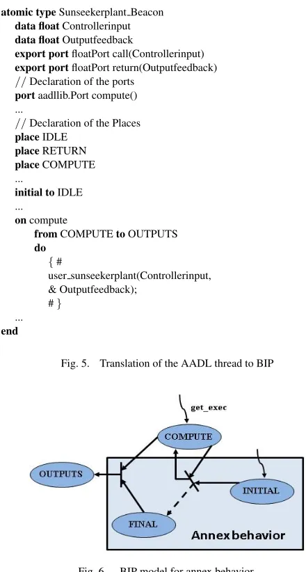
Figure 5 corresponds to the translation of the AADL thread to BIP. The link to the external file is described by a function call by matching the parameters of the thread during a transition from stateCOMPUTEto the stateOUTPUTSthrough an interaction. 3.3.2 Using annex behavior specification . The implementation of thread behavior is described in this case by using the annex be-havior specification [1]. The translation of AADL thread to BIP using behavior annex is described in Figure 6. As the figure shows, the behavior is always connected to the stateCOMPUTEto allow it to interact on the portpreemptto access on the stateRESUME.
atomic typeSunseekerplant Beacon
data floatControllerinput
data floatOutputfeedback
export portfloatPort call(Controllerinput)
export portfloatPort return(Outputfeedback) //Declaration of the ports
portaadllib.Port compute() ...
//Declaration of the Places
placeIDLE
placeRETURN
placeCOMPUTE ...
initial toIDLE ...
oncompute
fromCOMPUTEtoOUTPUTS
do
{#
user sunseekerplant(Controllerinput, & Outputfeedback);
#} ...
end
Fig. 5. Translation of the AADL thread to BIP
Fig. 6. BIP model for annex behavior
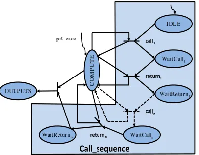
3.3.3 Using sequence of subprograms calls . In this case, we con-sider that the behavior of the thread consists of executing the call sequence of subprograms. A call to the subprograms in the AADL thread implementation is modeled in BIP as shown in Figure 7. This figure shows that the thread calls a subprogram through the portcall, which expresses the call and send of the parameters to the subprogram and thereturnport expresses the end of the execution and the return of the parameters of the subprogram.
3.4 Prototyping Distributed Implementation
[image:4.612.115.231.67.123.2]Fig. 7. BIP model for subprograms calls
Fig. 8. Deployment
mismatch in the application is reported by the analysis BIP tool chain.
AADL is expressive enough to detail the deployment view of the application: threads, processors, buses, threads on each process; properties refine the type of tasks (periodicity, priority), and their associated implementation. We defined our distribution model as a set of sender/receiver. It is supported by an AADL architectural model that defines the location of each system and the payload of the message exchanged as a thread-port name plus possible addi-tional data.
Figure 8 shows the steps for generating from a distributed AADL system’s description an executable distributed application as fol-lows:
(1) Identify each system and a connector’s mapped to the bus. (2) Generate for each AADL system its corresponding description
in BIP, and for each connector’s mapped to the bus a commu-nication protocol.
(3) Compile BIP system and generate an executable for each sys-tem with communication protocol.
(4) Run and debug the distributed application.
Our protocol supports communication between two or more com-puters. It provides a full-duplex communication channel between
processes that do not necessarily run on the same computer. We consider channels for data exchange among multiple threads in one or more processes are managed by the BIP Engine, if processes are running on one computer. Otherwise, if processes are running on different computers connected by a network, we use a network communication protocol. Before sending data through network to a server, we initially convert into encoded version before being trans-ported (suitable for network transfer). After receiving data (Server side), it can be converted back.
Most network communication protocols use the client server model. These terms refer to the two machines which will be com-municating with each other. One of the two machines, the client, connects to the other machine, the server, typically to make a re-quest for information. Notice that the client needs to know of the existence of and the address of the server, but the server does not need to know the address of the client prior to the connection being established.
Our protocol uses sockets. Sockets are associated with the concept of network communication in the form of client-server program-ming; a pair of processes of which one will be a client and one a server. The client process will send requests to the server. Of course, when creating a socket, we have to specify the type of com-munication that will be needed, since different modes of communi-cation require different protocols.
The generated BIP code provides a framework that will directly call user code when necessary. This allows a rapid and flexible design of the distributed system and does not restrict the user implementa-tions.
4. CASE STUDY
4.1 Precision Time Protocol
The Precision Time Protocol (PTP) [16] is a time-transfer protocol defined in the IEEE 1588-2002 standard that allows precise syn-chronization of networks (e.g., Ethernet). The goal of this protocol is to have a set of slave devices determine the offset between time measurements on their clocks and time measurements on a master device.
In the protocol, the master device periodically launches an ex-change of messages with slave devices to help each slave clock recompute the offset between its clock and the master’s clock. This offset will drift with time, and so these periodic exchanges mitigate the impact of this drift on clock synchronization.
One assumption is that this exchange of messages happens over a period of time so small that this offset can safely be considered constant. Another assumption is that the transit time of a message going from the master to a slave is equal to the transit time of a mes-sage going from the slave to the master. Finally, it is assumed that both the master and slave can measure the time they send or receive a message. The degree to which these assumptions are enforced in an application regulate the accuracy of the offset measured at a slave device.
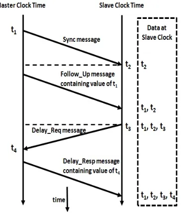
Synchronization messages are passed every two seconds to keep network resource usage at a minimum. Figure 9 shows the commu-nication steps between the master and slave as follows :
(1) In the so called Sync-Message, the master sends its current time to the slave where a time stamp is generated exactly when the message is received.
Fig. 9. Precision Time Protocol
(3) In order to eliminate the real-time clock delay of the slave due to the time it took the packet to travel over the network, the slave sends a so called Delay-request message to the master and notes the exact sending time.
(4) The master then replies with the time-stamp when the Delay-request message was received. The slave can then compute the exact time of the master clock and finalize the synchronization. (5) Further statistical methods are used to constantly adjust the real-time clock to correct for any residual fluctuations from the physical layer, network, repeaters and switches.
4.2 Modeling a Precision Time Protocol using AADL
To model the Precision Time Protocol of Section 4.1 in AADL, we consider what components the architecture consists of. Taking into account that each master or slave has a specific function and inter-face, and uses this interface to communicate, it seems reasonable to model each part as a separate component.
AADL provides a component category to model the functionality of a Master and Slave. However, we model each part as thread component and data component declarations inside System com-ponent. Threads in this model represent the interface of the Master and Slave, data components represent formats defined in the proto-cols (message containing time value). Threads model the services offeral by each part, i.e., they allow to send and receive messages from network entities for each period.
As described in Section 4.1, Master sendsSync, Follow Upand delay respmessages, and receivesdelay reqmessage. The repre-sentation of Master thread interface is shown in Figure 4.2. AADL process components model space partitions in terms of vir-tual address spaces containing source text that forms complete pro-grams as defined in the applicable programming language standard, they must contain at least one thread. The representation of Mas-ter process inMas-terface and connections between thread is shown in Figure 10.
Along with the structural properties, we modeled behavioral prop-erties of the PTP. The behavior of the Master thread is modeled by means of annex behavior specification. Figure 12 shows the part
threadMaster features
Sync: out data portinteger; Follow Up: out data portinteger; Delay Req: in data portinteger; Delay Resp: out data portinteger; properties
Dispatch protocol=>Periodic; Period =>200ms;
endMaster;
Fig. 10. AADL model of Master
processMaster features
Sync: out data portinteger; Follow Up: out data portinteger; Delay Req: in data portinteger; Delay Resp: out data portinteger; endMaster;
process implementationMaster.impl subcomponent
M :threadMaster; connections
data portM.Sync->Sync;
data portM.Follow Up->Follow Up; data portDelay Req->M.Delay Req; data portM.Delay Resp->Delay Resp; endMaster.impl;
Fig. 11. Software Model of Master
of the behavioral specification of the Master thread, that contains states and transitions. For each transition the thread can send or re-ceive the data. The datatmrepresents the drifting clock,t1andt4 represents the timestamps.
thread implementationMaster.Impl
annex behavior specification{** states
SYNC : initial state; FOLLOW : state; REQ : state; RESP : state;
transitions
SYNC -[ ]->FOLLOW{t1:= tm; Sync!();}; FOLLOW -[ ]->REQ{Follow Up!(t1);}; REQ -[ ]->RESP{t4:= tm; Delay Req?();}; RESP -[ ]->SYNC{Delay Resp!(t4);};
**}; endMaster.Impl;
Fig. 12. Behavioral Specification of Master
thread implementationSlave.Impl
annex behavior specification{** states
SYNC : initial state; FOLLOW : state; REQ : state; RESP : state;
transitions
SYNC -[ ]->FOLLOW{t2:= ts; Sync?();}; FOLLOW -[ ]->REQ{Follow Up?(t1);}; REQ -[ ]->RESP{t3:= t4; Delay Req!();}; RESP -[ ]->SYNC{Delay Resp?(t4);
o := (t2 + t3 - t1 -t4)/2; ts = ts - o;};
**}; endSlave.Impl;
Fig. 13. Behavioral Specification of Slave
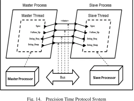
Figure 14 shows the software and hardware view of our case study. This model gathers typical elements from distributed systems, with a set of periodic tasks devoted to the processing of incoming orders. These two entities work at the same rates and should all respect their deadlines.
The software part represents how the processing is distributed onto different entities (threads) and gathered as AADL processes to form partitions. The next step is to map this part onto a physical hard-ware, so that processor resources can be associated to each process. The graphical representation of the deployment view of the system shows the global architecture of the application (number of pro-cesses and their mapping to hardware components). It indicates that each process is bound to a specific processor and how the commu-nication between processors occurs, using different buses. In this case we use one bus that binds connections.
These two parts are expressed using the same modeling notation. They can be merged to form the complete system: interacting en-tities in the software part represent the processing logic of the sys-tem, whereas the hardware part completes the system deployment information by allocating resources.
Our PTP case study is built by creating software component and mapping entities onto a hardware architecture. The flexibility of AADL allows us to partially define components and use them in other components. This is very useful during the first steps of pro-totyping where every detail of the system is not yet clear. Details can be added to these components either by means of AADL prop-erties or by component extension, without having to redefine all other components. PTP can be applied to more than one slave, in our case we consider one slave to keep the architecture clear.
4.3 Validation
The AADL model of the Precision Time Protocol System is trans-formed into BIP automatically by using our AADL to BIP transla-tion tool. The generatransla-tion of BIP code helps us to rapidly prototype the PTP case study and make it to a distributed application using our communication protocol between each partition. The prototype helped us to analyze the case study in a native platform in order to easily debug and evaluate it before running it on an embedded platform.
[image:7.612.323.551.69.241.2]The separation between software and hardware in AADL allows the programmer to model all the software parts of his application and test it with a native platform (generally a PC). If the tests are
Fig. 14. Precision Time Protocol System
AADL BIP
Master Slave
Components 10 6 6
Connectors 12 12 12
Lines of code 200 170 150
Fig. 15. Comparison between AADL & BIP
successful, the same software part can be reused with the actual hardware AADL.
In the PTP case study, we generate for each AADL partition mapped to the processor, its corresponding description in BIP, and for each connection mapped to the bus a network communication protocol (sender/receiver). We compile BIP partitions and we gen-erate an executable model. Then, we put every executable in the native platform (PC). First, we launch a receiver executable and then the sender executable. When the network protocol communi-cation is initialized between the sender and receiver, the exchange of data is started.
Once the executable model has been launched, interactive simula-tion and debugging is useful for understanding the working of the distributed application. This helped us to verify each interaction step by step, to know which state or port is activated, and to see the value of data received/sender.
Figure 15 summarizes the size of lines of code, number of com-ponents and connectors in AADL and respectively the BIP code for the PTP case study. We split the BIP in two parts because we generate for each Master or Slave components a corresponding BIP description system.
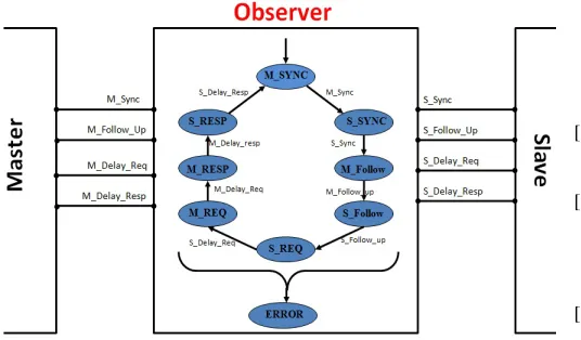
In addition, we use BIP observer to express and check require-ments. Observers allow us to express in a much simple manner most safety requirements. We apply this technique to verify two properties:
• Thread deadline: If the execution time of a thread exceeds its deadline the observer moves to an error state.
portM Sync. In the stateS SYNC, theObservercomponent are waiting the synchronization with the Slave thread through an in-teraction on the portS Sync. For example, if the matser send Fol-low Upmessage and send aDelay respmessage without receiv-ing theDelay Reqmessage the Observer moves to an error state. These analysis allow to fully assess system viability, to refine and to correct the behavior of a system.
Fig. 16. Observer model in BIP
5. CONCLUSION
Prototyping distributed applications can be extremely useful in evaluating a design, and also in understanding the effect of differ-ent parameters on the performance of an application. We selected the Architecture Analysis and Design Language that provide ade-quate syntax and semantics to express and support distributed em-bedded systems. In this paper, we proposed a general methodology for translating AADL thread component depending on the thread implementation into the BIP language. We proposed also a general methodology for prototyping distributed applications using the Pre-cision Time Protocol (PTP). In addition, we modeled and translated the case study from AADL into BIP. The executable application is tested and analyzed for soundness, any mismatch in the application is reported by the analysis BIP tool chain.
In the future we are working on the retime clocks. This will al-low real-time distributed algorithms to be implemented, and timing properties to be studied.
6. REFERENCES
[1] Annex Behavior Specification SAE AS5506.
[2] SAE. Architecture Analysis & Design Language (stan-dard SAE AS5506), September 2004, available at http://www.sae.org.
[3] SEI. Open Source AADL Tool Environment. http://la.sei.cmu.edu/aadlinfosite/ OpenSourceAADL-ToolEnvironment.html.
[4] TOPCASED: http://www.topcased.org/.
[5] A. Basu, S. Bensalem, M. Gallien, F. Ingrand, C. Lesire, T.H. Nguyen, and J. Sifakis. Incremental component-based con-struction and verification of a robotic system. InProceedings of ECAI’08, Patras, Greece, 2008.
[6] A. Basu, M. Bozga, and J. Sifakis. Modeling heterogeneous real-time components in bip. InProceedings of SEFM ’06, Pune, India, pages 3–12. IEEE Computer Society, 2006. [7] A. Basu, L. Mounier, M. Poulhi`es, J. Pulou, and J. Sifakis.
Using bip for modeling and verification of networked systems – a case study on tinyos-based networks. InProceedings of NCA’07, Cambridge, MA USA, pages 257–260, 2007. [8] S. Bensalem, M. Bozga, J. Sifakis, and T.H. Nguyen.
Com-positional verification for component-based systems and ap-plication. In Proceedings of ATVA’08, Seoul, South Korea, 2008.
[9] M. Bozga, J-C. Fernandez, A. Kerbrat, and L. Mounier. Proto-col verification with the aldebaran toolset. STTT, 1:166–183, 1997.
[10] M. Bozga, S. Graf, Il. Ober, Iul. Ober, and J. Sifakis. The if toolset. InProceedings of SFM’04, Bertinoro, Italy, volume 3185 ofLNCS, pages 237–267.
[11] Mohamed Yassin Chkouri and Marius Bozga. Determinis-tic data flow communication in aadl. InProceedings of the 2009 International Conference on Embedded Software and Systems, ICESS ’09, pages 93–100. IEEE Computer Society, 2009.
[12] M.Y. Chkouri.Modeling of real-time embedded systems using AADL for the automatic generation of applications formally verified. PhD thesis, VERIMAG- University Joseph Fourier, 2010.
[13] M.Y. Chkouri, A. Robert, M. Bozga, and J. Sifakis. Translat-ing AADL into BIP - Application to the Verification of Real-Time Systems. InModels in Software Engineering: Work-shops and Symposia at MODELS 2008, Toulouse, France, September 28 - October 3, 2008., pages 5–19.
[14] J. Sifakis G. Gossler. Composition for component-based modeling. Science of Computer Programming, 55:161–183, March 2005.
[15] J. Hugues, B. Zalila, L. Pautet, and F. Kordon. Rapid Pro-totyping of Distributed Real-Time Embedded Systems Using the AADL and Ocarina. InProceedings of the 18th IEEE In-ternational Workshop on Rapid System Prototyping (RSP’07), pages 106–112, Porto Alegre, Brazil, May 2007. IEEE Com-puter Society Press.
[16] Kang Lee and John Eidson. Ieee-1588 standard for a precision clock synchronization protocol for networked measurement and control systems. InIn 34 th Annual Precise Time and Time Interval (PTTI) Meeting, pages 98–105, 2002.
[17] M. Poulhi`es, J. Pulou, C. Rippert, and J. Sifakis. A methodol-ogy and supporting tools for the development of component-based embedded systems. In13th Monterey Workshop, Paris, France, volume 4888 ofLNCS, pages 75–96, 2006.