Fast Detection Process for Downlink in LTE Networks
Yamaan Esmiel Majeed
University of Baghdad Collage of Engineering
Akram Jabbar Abdullhussain
University of Baghdad Collage of Engineering
ABSTRACT
The goal of this paper is to introduce a simple detection method that gives a better performance with minimum computational complexity for the long term evolution (LTE) mobile communication system. The LTE communication system has been simulated using MATLAB®7 programming language. An approximated linear baseband model for the two modulation techniques used by the LTE system (which is the Quadrature Phase Shift Keying (QPSK) and sixteen-level Amplitude Modulation (16-QAM)) have been simulated. Three receivers have been tested. All these receivers used Least Square (LS) channel estimator. These receivers uses channel compensator, subjected to the accurate equation of the channel equalizer, and perturbation algorithm.
The results of the computer simulation shows that the perturbation algorithm gives an enhancement in the receiver performance of about 2 dB in different mobile channels than subjected to the accurate equation of the channel equalizer and about 4 dB than channel compensator.
Keywords
LTE, OFDM, perturbation process, 16QAM
1. INTRODUCTION
The great development in the computer devices that makes them small and easy to use led to the emergence of the smart mobile devices (like iPhone, and BlackBerry) which increases the demand for more data rates. Watching a video on a tablet such as Apple’s iPad become a usual habit, which puts a great stress on the wireless network especially that users prefer to watch high-definition video formats. All this has led to the need for continues evolution in wireless communication networks in order to cover the growing need for higher data rates for the users and introducing a higher quality of service. 3GPP technologies have evolved from GSM-EDGE, to UMTS-HSPA-HSPA+, to now initial LTE deployments, to provide increased capacity and user experience [1].
LTE is a packet switching network based on TCP/IP protocol, i.e. it is an all-IP network. LTE networks have a high spectrum efficiency that make it possible to reduce the cost per bit, also it have several advantages for users by improving the performance of the network. LTE is compatible with both 3GPP and non-3GPP old systems, so it can be co-exist with WCDMA systems, guaranteeing to operators the possibility of a smooth adoption of LTE, while continuing to use their previous technologies [2].
1.1 Literature review
In 2003, Jan C. Olivier, Sang-Yick Leong, Chengshan Xiaoand and Karl D. Mann in their published paper in [3] present a new method for channel equalization and symbol detection of an enhanced data rate for global system for mobile (GSM) communication and IS-136 evolution (EDGE) cellular system.
In 2004, Sarperi, Nandi, and Zhu have proposed in their published paper in [4] a detection technique for MIMO-OFDM systems based on the Blind Source Separation (BSS) technique.
In 2007, Jaewon Chang, Gwyun Jin, Seongmin Kim, Bin-Chul Ihm, and Wonjin Sung have proposed in their published paper in [5] an adaptive signal detection strategy of dual-antenna terminals which can enhance the reception quality and the system bandwidth efficiency
In 2008, Carles Navarro Manch´on, Luc Deneire, Preben Mogensen and Troels B. Sørensen have proposed in their published paper in [6] different multiple-input multiple-output (MIMO) receiver structures based on MMSE filtering and sequential interference cancellation (SIC) for the downlink of the 3GPP long term evolution (LTE) system.
In 2009, Shengbing Cai, Zhemin Duan and Jin Gao in their published paper in [7] focus on the deployment of of virtual MIMO in the UTRA LTE uplink and proposed two different received detection algorithms,namely Zero- Forcing and Minimum Mean Squared Error Successive Interference Cancellation
In 2010, Mohammad Ali Shah, Bj¨orn Mennenga and Gerhard Fettweis have proposed in their published paper in [8] MIMO detection methods based on Sphere detection for 3GPP LTE system.
In 2013, Xuanli Wu1,2, Lukuan Sun1, Mingxin Luo1 have proposed in their published paper in [9] An adaptive MIMO detection algorithm for LTE-A system which is based on sphere detection.
2. LTE SIMULATED BLOCK DIAGRAM
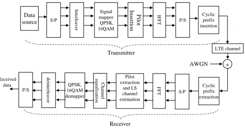
The OFDM UMTS-LTE simulated block diagram illustrated in figure 1. In particular the transmitter is based on conventional Orthogonal Frequency Division Multiplexing (OFDM) system structure.
2.1 LTE transmitter
The upper branch in figure 1 represents the OFDM based transmitter part, which includes source generator, interleaver, pilot insertion , IFFT, and the cyclic prefix insertion, the lower branch in figure 3.1 represents the OFDM based receiver part which includes cyclic prefix extaction, FFT, pilot extraction, chnnel estimation and equalization, demodulator and deinterleaver[10].
Firstly generated the input data using the uniform distribution random number generation. The second block is the interleaver. Interleaving is a mechanism used to counteract error burst. It is the reshuffling of the bits before they are sent over the fading radio channel.
format (in LTE QPSK ,16QAM and 64QAM modulation schemes are used)in the fourth block. These higher modulation or constellation schemes are required to achieve bandwidth efficiency and high data rates in LTE. This will convert the data to corresponding value of M-ary constellation which is complex word, i.e. real and imaginary part. The pilot sub-carriers are inserted in the 5th block, this pilot will be use to make channel estimation that's used in the receiver to compensate the channel effects on the signal.
After pilot insertion, the complex words frame and pilots frame will pass to IFFT block to generate an OFDM symbol. In OFDM modulation the high data rate serial stream is divided into a number of parallel streams
and then these low‐rate parallel streams are transmitted over different subcarriers simultaneously. Then the data will be back converted into serial form in the 7th block. Finally in the 8th block the cyclic prefix is added to each OFDM symbol by copying the end of a symbol and appending this to the start of the symbol and transmitted through the channel.
2.2 LTE channel
The LTE channel is a multipath channel which can be modeled as a dynamic transversal (FIR) filter as shown in Figure 2. The channel is time-variant due to time variations in the structure of the medium and due to the mobile motion. The input signal Sb(t) is passed through a tapped delay line which has a number of taps. Each tap represents a received signal path and the signals of all taps are summed together to produce the received signal. The delay blocks τ1 to τn represent the time delays between different paths while zo to zn represent the paths attenuations. Each tap (path) can be set to fade independently by a Rayleigh function Ro to Rn (performed by a Rayleigh fading simulator).
These functions (R0 to Rn) represents the Rayleigh fading phenomena results from the local reflections and diffractions near the mobile station. Each path has different fade due to the different objects that cause the local reflections near the mobile station. LTE specifications define three different channel models and these are used to specify performance of the user equipment (and the enode B) receivers. Each model is defined in terms of the delays (τn), relative amplitudes (zn)
of its paths, and the mobile speed (that will determine the Doppler frequency shift). The w(t) is the White Gaussian Noise that is added to the transmitted signal. Each channel is defined by a six-tap model, however some channels are defined by nine-tap models specified for use with larger simulators.
After the modulation of the data bits, the modulated symbols will be transmitted along the mobile channel, in this work (Pedestrian-A at 3 km/h and Vehicular-A at 120 km/h) which is a multipath fading channel. These symbols will arrive at the receiver with severe distortion [11].
In
ter
leav
er
Signal mapper QPSK, 16QAM
Cyclic prefix insertion
LTE channel
Transmitter
Data
source
+
S/PP
il
ot
Inse
rtion
IFFT P/SAWGN
Cyclic prefix extraction S/P
FFT
Pilot extraction
and LS channel estimation
C
h
an
n
el
eq
u
aliza
tio
n
QPSK, 16QAM demapper
d
ei
n
ter
leav
er
P/S Received
data
[image:2.595.55.556.68.331.2]Receiver
[image:2.595.332.535.463.610.2]Figure 1 LTE baseband simulated block diagram
2.3 LTE receiver
The mobile receivers are small and have stringent power consumption constraints, the design of the receiver should meet specific requirements to assure low complexity and low cost at the same time. A number of receivers have been simulated to get the best receiver performance with minimum complexity. At the receiver side, the reverse operation of the transmitter with some additional operations (e.g., channel estimation and equalization) will be done in order to find the estimates of multipath channel to recover information properly.
In the first block, the receiver has to remove the guard period (introduced in the transmitter) from the received signals. This operation is also called de-cyclic prefix. In the 2nd block the serial information are converted to parallel form .The serial to parallel conversion is followed by the Fast Fourier Transform (FFT) operation (which is the reverse the effect of the IFFT done in the transmitter) in order to recover the modulated symbols for all sub-carriers and to convert them into the frequency-domain. The channel estimation is done in the 4th block, which the Reference symbols are extracted from each sub‐frame to estimates the channel impulse response by least square channel estimation. The LS estimator minimizes the parameter (Y-XH)H(Y-XH), where (*)H means the conjugate transpose operation. It is shown that the LS estimator of H is given by [12][13]
HLS =X-1 Y = [(XK/YK)]T ………… (1)
3. DETECTION STAGE
In the LTE downlink an OFDM is used using QPSK and 16QAM modulation schemes, Due to the propagation of the transmitted signal over the multipath channels, it is subjected to a number of impairments (i.e. attenuation and amplitude-phase distortion) result in inter-carrier and inter-symbol interference to the OFDM system. So the channel estimation and channel equalization is considered to be necessary. Three methods have been presented in this paper .after that the complex constellation symbols are de‐mapped into binary values and this parallel data is converted in serial data, then the serial data are deinterleave to find out the estimates of the transmitted data.
3.1 Channel compensator
This is a simple method that it use pilot signal to make channel estimation then the channel estimation used to compensate the channel effects on the signal by multiply the signal by the inverse of the channel.
X=[Xpilot Xdata] ………… (2) Y=[Ypilot Ydata] ………… (3) HLS=Xpilot-1Ypilot ………… (4) Ycomp=Ydata HLS
-1
………… (5)
Where X is the transmitted signal that contain both pilot signal and user data signal, Y is the received signal also contain pilot signal and user data signal , HLs is the impulse response of the channel that estimated by least square channel estimation method and Ycomp is the compensated signal.
3.2 Subjected to the accurate equation of
the channel equalizer
In the detection processes, the decision process will be take account of the signal distortion that has been introduced by the channel. The detector takes full account of the intersymbol interference. This is done by removing the intersymbol interference (introduced by the channel) from the received symbol. With the appropriate estimation of the channel in the receiver, the message will be detect correctly. MMSE equalizer minimizes the probability of error in the detection of the received message. However, it is depend on the channel estimation accuracy [14].
We assume we detects the sk-1, sk-2, …., sk-6 correctly , the received signal r is given by
rk=skh[0]+ sk-1h[1]+ sk-2h[2]+ ……..+ sk-6h[6]+wk …..(6)
The term two through term six equation (5) are intersymbol interference then the equalized signal is given by subtracting the intersymbol interference from received signal
requalized=rk- {sk-1h[1]+ sk-2h[2]+ sk-3h[3]+ …..+ sk-6h[6]} ... (7)
then
requalized= skh[0]+ wk ………… (8)
This signal will pass through threshold detector to eliminate the AWGN from signal.
3.3 Perturbation method
A least-squares (LS) channel estimation has been used to estimate the overall-channel impulse-response vector h, Denoting the received sequence by z, we have
Z=Bd+n …………. (9)
Where d is the unknown transmitted burst to be estimated and n is additive noise. The matrix B is lower triangular, with rows containing the post impulse response (IR) as
…….(10)
B is a diagonally dominant matrix and of full rank. A computationally efficient algorithm can be developed to detect the transmitted symbol vector d by minimizing
with respect to d. a two-step optimization
procedure is proposed to find the symbol vector that will minimize the sequence error [3].
Equalization and Symbol-Detection Algorithm
We assume we detects the sk-1, sk-2, …., sk-6 correctly , the received signal r is given by
and the cost C1,k is given by
C1,k= ………… (12)
in this system sk is taken the possible value xk for which the cost is minimum over all the combination of xk .this involve the computation of only 16 different values of c1,k since ,for any one value of xk that minimize c1,k are determined by a process of simple threshold comparison
in this method, the detector determines first, by simple threshold comparison ,the value of xk that has least cost which it minimize the c1,k, ,then depending on the xk that have least cost we detect the xk+1 by the same method until the end of the message.
Step one: starting sk with k=0,selsct16-QAM alphabet hard symbol sk that yields the least value for
Repeat the search for the next symbol sk+1 using previously detected symbols sk ,and the next symbol sk+2 using previously detected symbols sk and sk+1 and so on until the end of the message, then we will have received vector s*.
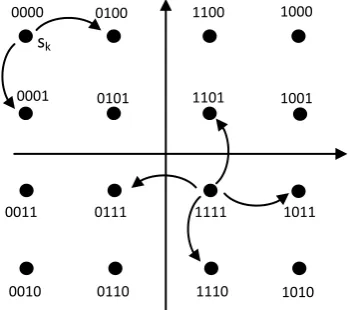
Step two: use the obtained s* as initial solution, starting from the end of the message by test in the nearest neighbors of the detected symbol sk in the 16-QAM constellation for the possible reduction in the sequence error e2. If the sequence error is reduced (or most reduce) by one of the neighbors , then we
will update sk with that neighbor that gave minimum square error e2. Then test the nearest neighbors of the detected symbol sk-1 in the 16-QAM constellation for the possible reduction in the sequence error e2 .If the sequence error is reduced (or most reduce)by one of the neighbors. , then we will update sk-1with that neighbor that gave minimum square error e2 .Repeat this process for sk-2 and so on until the beginning of the message .this updated s is then the final estimate of the transmitted hard symbol vector in the sequence sense denoted by sk sequence .The idea of nearest-neighbor perturbation is shown inFigure 3.
4. RESULTS AND DISSCUSSION
[image:4.595.89.264.350.505.2]The results of the three detection algorithms for the LTE channels will be examined and compared. The effects of wireless channels on the system will be discussed. The simulated standard mobile channels are Extended Pedestrian A (EPA) model and an Extended Vehicular A (EVA). We have a number of programs constructed to simulate the LTE downlink system and the different reception techniques used in this work. All computer programs used here written in Matlab7 programming language. The results were obtained by sending many packets and the error in the bits are obtained and calculated.
Figure 5 illustrates the performance of LTE system for QPSK modulation in Rayleigh fading AWGN channel(ped-A). It can be seen that the perturbation is better than the channel compensator, In this case the gain is about 3 dB,and the perturbation is better than the subjected to exact channel equation equalizer about 2 dB.
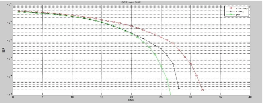
Figure 6 illustrates the performance of LTE system for 16QAM modulation in Rayleigh fading AWGN channel (ped-A).
It can be seen that the perturbation is better than the channel compensator, In this case the gain is about 5 dB,and the perturbation is better than the subjected to exact channel equation equalizer about 2 dB. In addition, it can be seen that the BER in figure 2 is less than that shown in figure 3 because the modulation technique is different, the QPSK has abetter performance than the 16QAM because the number of bits sent with each symbol in QPSK is less than that sent in 16QAM.
1000 1100
0100 0000
1001 1101
0101 0001
1011 1111
0111 0011
1010 1110
0110 0010
sk
[image:4.595.100.504.575.743.2]Figure 3 The idea of nearest-neighbor perturbation
Figure 7 illustrates the performance of LTE system for QPSK modulation in Rayleigh fading AWGN channel(veh-A).It can be seen that the perturbation is better than the channel compensator, In this case the gain is about 4 dB, and the
[image:5.595.85.511.74.241.2]perturbation is better than the subjected to exact channel equation equalizer about 3 dB.
[image:5.595.87.512.283.461.2]Figure 6 Performance of LTE system for 16QAM modulation in rayliegh fading+AWGN chnnel (ped-A)
[image:5.595.88.510.503.679.2]Figure 7 Performance of LTE system for QPSK modulation in rayliegh fading+AWGN chnnel (veh-A)
Figure 8 illustrates the performance of LTE system for 16QAM modulation in Rayleigh fading AWGN channel (ped-A).
It can be seen that the perturbation method is better than the channel compensator, In this case the gain is about 6 dB, and the perturbation is better than the subjected to exact channel equation equalizer about 3 dB. The BER for the veh-A channel is more than ped-A channel because the ped-A channel has less distortion effect than the veh-A channel because of the speed of the mobile station.
In addition, it can be seen that the BER in the figure 5 is better than BER in the figure 6 because QPSK modulation has abetter performance than the 16QPSK modulation because the it sent less number of bits with each symbol than 16QPSK. From the results shown above, we can see that the petrbuation method has a better performance than the other two methods because it is more complex and it needs more calculation time than the other two methods, this extended time need to cheaks more than one symbol (it cheaks all neighbor for each symbol).
5. CONCLUSION
In this work the different parts of the simulated OFDM-LTE transceiver chain together with various performance results based on simulation in MATLAB
®
7. The aim of this paper is to introduce simple detection methods for the LTE system the performance of the proposed methods has been tested under different propagation conditions and the results has been compared for the different receiver structures.
After completion of this work and from the results obtained following point can be concluded:
1. Petrubation method gives the better performance than other two methods because it is more complex than the other two methods
2. As the speed of the mobile station increases, the bit error rate increase as shown from results obtained from the two channel models. pedestreain –A which is low speed of mobile user (3km/h) has abetter performance than vehucilar-A where the mobile speed (120km/h). 3. Increas the number of bits sent with each symbol
increase the bit error rate as obtained from results of chapter four, the QPSK has abetter performance than the 16QAM because the number of bits sent with each symbol in QPSK is less than that sent in 16QAM.
6. REFERENCES
[1] 4G Americas. “4G Mobile Broadband Evolution: 3GPP Release 10 and Beyond”. Feb. 2011.
[2] UMTS forum. “Mobile Broadband Evolution: the roadmap from HSPA to LTE”. Feb. 2009.
[3] Jan C. Olivier, Sang-Yick Leong, Chengshan Xiao, and Karl D. Mann "Efficient Equalization and Symbol
Detection for 8-PSK EDGE Cellular System" IEEE TRANSACTIONS ON VEHICULAR TECHNOLOGY, VOL. 52, NO. 3, MAY 2003.
[4] Luciano Sarperi_, Asoke K. Nandi, and Xu Zhu “Multiuser Detection and Channel Estimation in MIMO OFDM Systems via Blind Source Separation”. Puntonet and A. Prieto (Eds.): ICA 2004, LNCS 3195, pp. 1189– 1196, 2004.
[5] Jaewon Chang, Gwyun Jin, Seongmin Kim, Bin-Chul Ihm and Wonjin Sung "A Location-Adaptive Signal Detection Scheme for Dual-Antenna Terminals Using Maximal Ratio Combining and Spatial Demultiplexing," Department of Electronic Engineering, Sogang University, 2007.
[6] Carles Navarro Manch´on, Luc Deneire, Preben Mogensen and Troels B. Sørensen 2008 "On the Design of a MIMO-SIC Receiver for LTE Downlink”, Department of Electronic Systems Aalborg University,.
[7] Shengbing Cai Zhemin Duan Jin Gao 2009 "Comparison of Different Virtual MIMO Detection Schemes for 3GPP LTE",Dept. of Electronics and Information, Northwestern Polytechnical University,.
[8] Mohammad Ali Shah and Bj¨orn Mennenga and Gerhard Fettweis 2010 "On the Design of a MIMO-SIC Receiver for LTE Downlink”, Department of Electronic Systems, Aalborg University,
[9] Xuanli Wu1, Lukuan Sun, Mingxin Luo 2013 Iterative Soft-In Soft-Out Sphere Detection for 3GPP LTE, Vodafone Chair Mobile Communication Systems Technische Universit¨at Dresden,.
[10] Ammar Osman , Abbas Mohammed " Performance Evaluation of a Low-Complexity OFDM UMTS-LTE System", Vehicular Technology Conference, 2008. pp. 2142 - 2146 VTC Spring 2008. IEEE
[11] A. Ancora, I. Toufik, A. Bury and D. Slock. “LTE – The UMTS Long Term Evolution: From Theory to Practice”. First Edition. West Sussex. John Wiley & Sons. pp. 113-121. 2009.
[12] Yushi Shen, Ed Martinez 2006 “Channel Estimation in OFDM Systems” Freescale Semiconductor, Inc.,
[13] SRI Xiao-jing, YINYa-fang ''Channel Estimation for TD-LTE System", pp. 923 – 925,Cross Strait Quad-Regional Radio Science and Wireless Technology Conference (CSQRWC), 2011