Comparison of Speed control of PMSM with PI, PID& Adaptive PID
Controllers
Jumana Beegum N S
1, Sheenu P
21PG Scholer, Control Systems,Mar Baselios College Of Engineering ,TVM, Kerala, India
2Assistant Professor,Electrical & Electronics Dept, Mar Baselios College Of Engineering ,TVM, Kerala, India
Abstrac
t
— This paper proposes a speed control scheme for permanent magnet synchronous motor (PMSM) drives usingdifferent control methods. The proposed controllers are PI, PID & Adaptive PID controller. The adaptive PID controller consist of three control terms namely, a decoupling term which is employed to compensate for nonlinear factors then the PID term is made to automatically adjust the control gains and the last one is supervisory term, designed to guarantee the system stability. It is an online tuning method, So it can adaptively deal with any system parameter uncertainties in reality. To confirm, which is the effective speed control technique, all the control techniques are simulated in MATLAB/ Simulink environment and the performance is compared .Finally it is validated that the adaptive PID controller has the advantages of robustness, easy implementation and adequate performance in the face of uncertainties.
Key words: Adaptive control, Proportional-integral-derivative (PID) controls, Permanent magnet synchronous motor (PMSM).
1. INTRODUCTION
Compared with other forms of machines permanent magnet synchronous motor (PMSM) are widely used because of its better dynamic performance, higher efficiency, smaller size, easy maintenance and so on. Now a days permanent magnet synchronous motor (PMSM) are extensively applied in home appliances as well as industrial applications such as wind generation systems, industrial robots, electric vehicles, air conditioners, washing machines, national defense, agriculture and daily life. The PMSM is not easy to control because of its nonlinearity. In the run time parameter variations are highly affected by the performance of PMSM [1]. So the design of PMSM must contain a high-performance controller which has a simple algorithm, fast response, high accuracy, and robustness against the motor parameter and load torque variations.
The proportional-integral (PI) & proportional-integral derivative (PID) controller are widely adopted to control the PMSM systems due to its simplicity, effectiveness, and clear functionality [10]. However the traditional PID controller is sensitive to the system uncertainties. Thus, the control performance of the conventional PID method can seriously degraded under parameter variations. The offline-tuning rules, such as a hybrid control system, which contains a fuzzy controller in the transient and a PI controller in the steady state and the fuzzy rules are employed for tuning the PI gains which have a lack the adaptability to deal with the time-varying system uncertainties An adaptive PI controller has online-tuning rules because it does not require the exact knowledge of any motor parameter
Recently, various advanced control methods are available for the control of the PMSM systems, such as fuzzy logic control (FLC), neutral network control (NNC), sliding mode control (SMC) adaptive control, etc. The FLC [5] is used because of its fuzzy reasoning capacity. However, the number of the fuzzy rules increases, the control accuracy increases but the control algorithm can be complex. The SMC have great properties such as robustness to external load disturbances and fast dynamic response so it is popularly used in the speed control of PMSM [9]. But it also subject to the parameter variations and chattering problems.
The adaptive control is an interesting method for the PMSM drives because it can deal with the motor parameter and load torque variations. Here only the stator inductances and load torque variations are considered and neglect stator resistance, moment of inertia, viscous friction coefficient, etc. Moreover, the adaptive control algorithm does not guarantee the convergence condition of the system error.
consist of adaptive tuning laws which are designed to online adjust the control gains using the supervisory gradient descent method. Therefore, when the motor parameters change the PID gains are automatically adjusted to attain the optimal values. So the proposed control system achieves a good regulation performance such as fast dynamic response and small steady-state error even under system parameter uncertainties. The stability analysis of the adaptive control strategy found by Lyapunov stability theories.
The organization of the rest of this paper can be summarized as follows. The key points while the design of Adaptive PID controller method is explained in Section 3. Different combinations of parameters from different control methods are taken and compared in this section. Conclusion based on the simulink work is given in Section 5.
2. SYSTEM MODEL DESCRIPTION
The modeling of PMSM drive system is required for proper simulation of the system. The d-q model has been developed on rotor reference frame. At any time t, the rotating rotor d-axis makes and angle θr with the fixed stator phase axis and rotating stator mmf makes an angle α with the rotor d-axis. Stator mmf rotates at the same speed as that of the rotor. Voltage equations in rotor reference frame is given by,
(1)
Where
d and
q are the flux linkages. The electromagnetic torque developed is given by,(2)
From the above equations the dq frame model is formed by
(3)
Where id , iq are direct and quadrature axis current, Ld , Lq are direct and quadrature axis inductances, R is the stator
resistance and P number of magnetic pole pairs. The system parameters k1 − k6 are depend on the values of Rs, Lq, J,B, and
ψm. Then
(4)
d r q q q qdt
d
i
R
V
q r d d d ddt
d
i
R
V
)
)
(
(
2
2
3
i
i
L
L
i
T
e m q q d d qp
i
L
L
i
L
R
L
v
dt
di
q d q r d d q dd
L
i
L
L
i
L
L
v
dt
di
q m r d q d r q q q qq R
J JT
i
i
L
L
J
p
i
J
p
dt
d
L r q d d q q mr
Then, the PMSM drive system model is rewritten as
(5)
.
2.1 Conventional PID with Decouping Term
The speed error and rotor acceleration are define as
(6)
where ωd is the desired speed.From the above equations , the dynamics equation derived as
(7)
In practical applications, supposed that the derivatives of ωd and TL can be neglected because of the desired speed and the
load torque vary slowly in the sampling period. Then, the system model (1) is,
(8)
Then, the second-order system as follows,
(9)
where λ is the positive control parameter.
Based on the basic theory of the feedback linearization control, the decoupling control term
where (10)
i
i
k
V
k
dt
di
q r d dd
4 1
T
k
k
i
k
dt
d
L r q r 3 21
k
i
i
k
V
k
dt
di
r d r q q q 5 46
T
k
k
i
k
q Ld e 3 5 1 .
i
V
k
i
k
i
T
k
k
i
V
k
k
i
k
k
q d d d L d q q d e
6 4 3 . 2 6 5 4 1 . . . . . .V
k
i
i
k
i
V
k
k
i
k
k
k
i
k
k
k
ds qs ds qs ds qs ds e 6 4 . 6 1 1 5 1 4 1 2 . .
V k i i k i V k k i k k k i k k k ds qs ds qs ds qs ds e e 6 4 . 6 1 1 5 1 4 1 2 . ..
u
u
u
f fT
f 1 2
k
i
i
k
u
k
k
k
i
k
k
k
i
k
k
From (9) and (10), the dynamic error system can be formulated as follows
(11)
Then, the conventional PID controller is the form
(12)
where B=diag[k1k6,k6], Uf is the decoupling control term to compensate for the nonlinear factors, and UPID is the PID
control term
(13)
Where (K1P, K2P), (K1I, K2I), and (K1D) are the proportional gains, integral gains, and derivative gain of the PID control term,
respectively. The state and gain matrices are given as
(14)
3. ADAPTIVE PID CONTROLLER DESIGN
The adaptive regulator is used in about the same way as a conventional PID, i.e. the purpose is to keep a measured value as close as possible to a given set point. The adaptive regulator has, however, a much more advanced internal structure and it is capable to change its own behaviour if the process changes. Therefore, the adaptive regulator is considerably more accurate in controlling an industrial process. A truly adaptive controller is capable of learning from previous events to improve future performance.
The conventional PID controller with the offline-tuned control gains can give a good control performance if the motor parameters (k1 to k6) are known.If the system parameters gradually change during operating time, the control performance can be seriously degraded, but the system parameters are not updated. Adaptive tuning laws for auto adjustment of the control gains are introduced to overcome this challenge. The supervisory gradient descent method is used for the proper adjustment of control gains. The proposed adaptive PID controller is the form,
(15)
where uf is the decoupling control term which compensates for the nonlinear factors , uPID is the PID control term which
includes the adaptive tuning laws, uS is the supervisory control term which guarantees the system stability, and uPID0 = EK0
is a constant coefficient matrix.
V
u
k
i
u
V
k
k
f ds f qs ds e e 2 6 . 1 6 1 . ..
u
u
V
V
V
k
V
k
k
V
f PIDds qs
ds qs
dqs B
6 6 1 EK dt dt D dt t dse I dse P t e D e I e P PID PID PID
i
k
i
k
d
k
k
k
u
u
u
0 2 2 0 1 1 1 2 1
k
k
k
k
k
i
i
P I D P I k dt dt E T ds t ds e t e
2 2 1 1 1 0 0 0 0 0 0 0
u
u
u
u
For getting proper adaptation laws, a new tracking error vector based on the reduced-order sliding mode dynamics is defined as,
i
s
s
ds e
t
t
t
s
2
1
. (16)
Based on SMC method, the sliding condition is deduced according to the Lyapunov stability theory. Commonly, the Lyapunov function for the SMC is given by
2
1
S
s
V
T . (17)Then, the sliding condition can be obtained from the Lyapunov stability theory as
The sliding condition guarantees that s→0 as t→∞. The adaptation laws for the control gains are the in the form,
(18)
Where γ1P , γ1I , γ1D , γ2P , and γ2I are the positive learning rates. The adaptive tuning laws can be expressed in the following vector form
where Φ= diag ( γ1P , γ1I , γ1D , γ2P , γ2I ).
The supervisory control term in (21) is necessary for pulling back the dynamic errors to the predetermined bounded region and guaranteeing the system stability. Assume that there exists an optimal PID control term
(19)
Where is the optimal gain matrix and are the approximation errors and they are assumed to be bounded by 0 ≤ |ε1| ≤ δ1 and 0 ≤ |ε2| ≤ δ2 in which δ1 and δ2 are the positive constants.
S
E
K
T.
U
U
PID PID0 *
K K K K K
K I P D I P
T 2 * 2 * 1 * 1 * 1 *
*
2 1
T
1 2T
Then, the supervisory control term is designed as,
(20)
The desired controller is obtained by combining the decoupling control term , PID control term with the adaptation laws , and supervisory control term as,
(21)
4.SIMULATION RESULTS
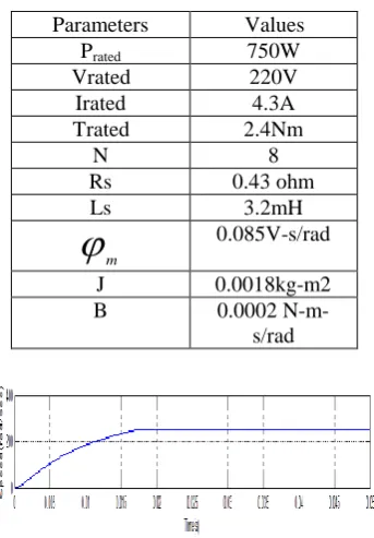
Simulations have been carried out for the speed control of PMSM with PI, PID &Adaptive PID controllers. The motor parameters used for simulation are given in table 1. first section discuss about the speed control of pmsm with PI controller.The simulation block is shown in Fig 1. The desired speed is choosen as 251.3 rad per seconds.
[image:6.595.196.399.346.428.2]Fig-1: Simulink model of PMSM with PI Controller
Table 1
:
PMSM Parameters
Chart-1:Simulation result of PMSM with PI Controller
Parameters Values
Prated 750W
Vrated 220V
Irated 4.3A
Trated 2.4Nm
N 8
Rs 0.43 ohm
Ls 3.2mH
m 0.085V-s/radJ 0.0018kg-m2
B 0.0002
N-m-s/rad
s
s
u
s2 2
1 1
sgn
.
sgn
.
u
u
u
[image:6.595.213.385.497.744.2]It can be observed that the motor speed settles down at the reference value of 251.3 rad/sec in 20.670 ms with a small oscillation or overshoot. From the plot for the output of the speed controller it is observed that there exist sudden spikes and dips around the instant when the motor speed has reached its reference value. The maximum peak overshoot is about 251.016.
Fig-2: Simulink model of PMSM with PID Controller
Then discuss about the speed control of pmsm with PID controller.The simulation block is shown in Fig 2. Here also the desired speed is choosen as 251.3 rad per seconds.The simulation result is shown in Chart 2. It can be observed that the motor speed settles down at the reference value of 251.3 rad/sec in 20.003 ms with a small overshoot.Here the settiling time is increased due to the noise in the derivative controller part. The maximum peak overshoot is about 253.249.
Chart-2: Simulation result of PMSM with PID Controller
Last section discuss about the speed control of pmsm with Adaptive PID controller. It consists of three control terms namely a decoupling term, a PID term, and a supervisory term.The simulation block is shown in Fig 3.
Fig-3:Simulink model of PMSM with PI Controller
the conventional control methods From the above result, the Adaptive PID Controller method has better response compared to other two methods
Table-2
:
Comparison of Motor ParametersChart-3:Simulation result of PMSM with Adaptive PID Controller
5.CONCLUSION
This paper proposes, the speed control scheme for permanent magnet synchronous motor (PMSM) drives using different control methods. The proposed control algorithm was simple and easy to implement in the practical applications. For comparison purpose, the PI & PID controller was tested at the same conditions. From the experimental results it is clear that the adaptive PID controller method gives better performance compared to the other two control techniques.
REFERENCES
[1] Jin-Woo Jung, Ton Duc Do, and Han Ho Choi “Adaptive PID Speed Control Design for Permanent Magnet Synchronous Motor Drives”, IEEE Transactions On Power Electronics, vol. 30, no. 2, pp. 900-908, february. 2015
[2] G.Wang, H. Zhan, G. Zhang, X. Gui, and D. Xu, “Adaptive compensation method of position estimation harmonic error for EMF-based observer in sensorless IPMSM drives,” IEEE Trans. Power Electron., vol. 29, no. 6, pp. 3055–3064, Jun. 2014.
[3] X. Zhang, L. Sun, K. Zhao, and L. Sun, “Nonlinear speed control for PMSM system using sliding-mode control and disturbance compensation techniques,” IEEE Trans. Power Electron., vol. 28, no. 3, pp. 1358–1365, Mar. 2013.
[4]A. V. Sant and K. R. Rajagopal, “PM synchronous motor speed control using hybrid fuzzy-PI with novel switching functions,” IEEE Trans. Magn., vol. 45, no. 10, pp. 4672–4675, Oct. 2009.
[5] K. Y. Lian, C. H. Chiang, and H. W. Tu, “LMI-based sensorless control of permanent-magnet synchronous motors,” IEEE Trans. Ind. Electron., vol. 54, no. 5, pp. 2769–2778, Oct. 2007.
[6] K. Y. Cheng and Y. Y. Tzou, “Fuzzy optimization techniques applied to the design of a digital PMSM servo drive,” IEEE Trans. Power Electron., vol. 19, no. 4, pp. 1085–1099, Jul. 2004
[7] T. D. Do, S. Kwak, H. H. Choi, and J. W. Jung, “Suboptimal control scheme design for interior permanent magnet synchronous motors: An SDRE-based approach,” IEEE Trans. Power Electron., vol. 29, no. 6, pp. 3020–3031, Jun. 2014.
[8] T. D. Do, H. H. Choi, and J. W. Jung, “SDRE-based near optimal control system design for PM synchronous motor,” IEEE Trans. Ind. Electron.,vol. 59, no. 11, pp. 4063–4074, Nov. 2012.
[9] V. Q. Leu, H. H. Choi, and J. W. Jung, “Fuzzy sliding mode speed controller for PM synchronous motors with a load torque observer,” IEEE Trans. Power Electron., vol. 27, no. 3, pp. 1530–1539, Mar. 2012.
[10] K. H. Ang, G. Chong, and Y. Li, “PID control system analysis, design, and technology,” IEEE Trans. Control Syst. Technol., vol. 13, no. 4, pp. 559–576, Jul. 2005.
Control
methods
Peak overshoot
Settling
time(ms)
Rise time(ms)
PI
Controller 251.016 20.670 12.290
PID
Controller 253.249 20.003 23.865
Adaptive PID Controller