2018 International Conference on Information, Electronic and Communication Engineering (IECE 2018) ISBN: 978-1-60595-585-8
A New Navigation Message Demodulation Algorithm for Satellite
Navigation Receiver
Bao LI
1, Yin-bing ZHU
1,*, Ke-jin CAO
1and Juan LI
21
Department of Navigation Engineering, Naval University of Engineering, Wuhan, China, 430033
2
College of Mechanical and Electrical Engineering, Qingdao Agricultural University, Qingdao, China, 266109
*Corresponding author
Keywords: Satellite navigation receiver, Demodulation, DFT, Angle compensation.
Abstract. A new navigation message demodulation algorithm for satellite navigation software receiver is researched. The detailed phase and frequency information of the carrier are obtained by analyzing the phase angle of the DFT component of the satellite navigation IF signal, and navigation messages are demodulated by adjusting the initial phase of the adjacent data block is π flipped or not. The detailed implementation steps of the method are presented, and the reason of phase angle discontinuity of kernel function is analyzed and compensated. Finally, the method is verified by simulation and actual signal respectively and compared with the traditional phase-locked loop method. The results show that the carrier frequency accuracy of new algorithm can reach 10 Hz, more precise than traditional method; signal tracking can effectively output navigation message information, the method with data block processing to obtain the phase angle is more suitable for software radio ideas.
Introduction
Since the concept of software receiving radio has been introduced into the design of satellite navigation receiver, satellite navigation software receiver has quickly become a research hotspot due
to its flexibility, scalability and economy[1]. The software receiver is divided into two parts: the RF
front-end and the baseband signal processing. The baseband signal processing algorithms of the traditional software receiver are mostly based on the frequency-domain FFT capture and phase-locked
loop tracking. The second-order PLL is usually used [2-4]. There are also suitable for high dynamic
second-order frequency-locked loop auxiliary third-order phase-locked loop structure [5,6]. This article
describes a new software receiver algorithm - BASS (synchronization block signal adjustment)
method. The basic idea was first proposed by the J.B.Y.TUSI in the United States [7]. The algorithm
obtains the carrier's fine frequency and navigation information by analyzing the phase angle of the DFT component of the satellite signal. Compared with the traditional software receiver algorithm, the BASS algorithm Effectively suppress noise, capture the carrier frequency is more accurate, simple
and quick calculation, more suitable for software and radio methods [8].
Principle of BASS
For satellite navigation IF digital signal ( )x n with C/A code peeled off, the DFT output is
2 1
0
( ) ( ) , 0 ~ 1
nk
N j
N
n
X k x n e k N
(1)Where, krepresents a frequency component, N is the total number of data points. The maximum
( )i
1 Im[ ( )]
tan
Re[ ( )] i
i X k X k
(2)
represents the carrier's initial phase of the Kernel function (
2 nk j
N e
). FFT is used to quickly find
the biggest component X k( )i of DFT. When the signal's useful frequency kiis known, it is directly
substituted into Equation (1) and (2).
In the case of the known carrier's coarse frequency, the two consecutive signals are calculated using
equations (1) and (2) respectively to obtain the phase angle tand t m . The fine frequency of the
carrier is:
2 2
t m t f
m m
(3)
Where, mis two consecutive signal interval time, in order to ensure that the calculation of the
uniqueness of the fine frequency, usually take less than 2 .
How to Use BASS in Satellite Navigation Receivers
Acquisition
Acquisition is the process of finding the satellite in the received navigation signal and obtaining the initial code phase and carrier frequency of the satellite in three steps. The following GPS single star as an example to illustrate the process, all the satellites to capture just loop through the implementation of this step.
(1) Obtain satellite initial code phase and carrier frequency. Take a digitized IF input signal of 1ms
(one C/A code cycle length), locally generate 21 carriers in a range of fi 10KHZ with an interval of
1 kHz, within the ideal mid-frequency range and multiply each frequency by 1 ms of digitized C/A code , Respectively, with the input signal loop related, usually using the parallel code FFT method to complete. If the maximum correlation value exceeds the threshold, the satellite is considered to exist. The code phase and carrier frequency corresponding to the maximum correlation value are the initial
code phase of the satellite and the carrier coarse frequency fc with a resolution of 1 kHz.
(2) Calculate the finer carrier frequency. Step (1) obtained in the initial code phase as a starting point, the local 1ms digitized C/A code and 1ms input signal multiplied to obtain an approximate
continuous wave ( )x n ,get two frequencies with 400HZ around the coarse frequencyfc, even coarse
Frequency obtained within the three frequency points were substituted into the equation (1) to calculate the three DFT components, the maximum amplitude component corresponding frequency is
the resolution of 400HZ finer carrier frequency ff .
(3) Get fine carrier frequency. This is the BASS method in the capture of the specific use. take M (M = 7) continuous 1ms input data, the local code to generate the initial position of the Mms digitized C / A code multiplied to get M 1ms signals , Using equation (2), (3) to find the initial phase angle
( 1 ~ )
i i M
of the M segment signal, the adjacent two-phase angle into equation (3) can be M-1
frequency, the average is the carrier fine frequencyf .
Tracking
Carrier Tracking. Carrier tracking to complete the carrier frequency and the initial phase of the precise tracking, but also can be divided into three steps.
(1) Adjust the input signal according to the starting position of C/A code so that the starting position is the beginning of C/A code, that is, the initial code phase of C/A code is 1, so as to ensure that each flip of the navigation message occurs In the starting position of 1ms data, the adjacent
millisecond phase difference is 0 or , so the navigation message is demodulated by the phase angle
inversion.
(2) To generate a local signal, the equation(2) calculates the initial phase of every millisecond data. The local signal is formed by multiplying the C/A code and the complex carrier, and the 1ms digitized C/A code repeatedly forms a local C/A code. The generation of local complex carrier should consider the continuity of the kernel function.
In general, in the operation of equation (2), ki is an integer. The initial phase angle of the kernel
function obtained from two consecutive signals is continuous, as shown in the following equation:
2 / 2 /
0
|
|
i i
j nk N j nk N
n N n
e
e
(4)However, carrier tracking ki is usually not an integer. In this case, the corresponding frequency of
i
k will be too far from the input signal frequency, which will result in the loss of signal processing
sensitivity and even loss of lock. When kiis not integer, the initial phase angles of the two continuous
data kernels are discontinuous, so that the navigation message can not be calculated by the initial phase reversal solution of the carrier relative kernel. Therefore, before generating the kernel function of 1ms, the kernel function Of the initial phase angle compensation to ensure the continuity of the phase angle of the kernel function. To sum up, the generation of local complex carriers needs to adjust the discontinuity of the phase angle compensation kernel function every millisecond, and the carrier frequency needs to be adjusted once in intervals, as shown in the following step (3).
(3) Local carrier frequency update. Taking into account the static case, the Doppler shift within ± 5KHZ, the impact on the carrier frequency is not large, every 10ms on the carrier frequency recalculation, the calculation method and the capture process (3) the same (M take 10 ).
After the phase angle compensation and carrier adjustment, there are two cases of the initial phase
of the adjacent millisecond data. First, there is no phase angle change. Second, there is phase shift
caused by the navigation message. Due to the influence of noise, the threshold can be properly relaxed. In this way, navigation message information is obtained. Since the navigation message
frequency is 50 Hz, no phase shift occurs within 20 ms, and it occurs only at an integer multiple of
20 ms after the relative initial time.
Code Tracking. Due to the Doppler shift, the initial position of the C/A code of the input signal is moving slowly, so the local C/A should also be adjusted to keep pace with the input signal. When the C/A code is aligned, the correlation value is 1023, and the correlation value is only three when shifted by one symbol: 63, -1, 65. For simplicity, the correlation values are assumed to be zero when the C/A code is offset by more than one symbol.
The locally generated three signals (E, P, and L) differ by half a symbol (d= 0.5) respectively.
Assuming distance betweenyp the ideal peak is x, that is the initial position of the C/A code. xis
calculated as follows:
1 1 l
e
y x d
r
y x d
(5)
(1 )(1 )
1
r d x
r
After capturing the maximum offset of x is half a sample period, from equation (5) can obtain the
corresponding threshold of r. The ratio between the two correlation values yields a r value that
exceeds the threshold to adjust locally generated three digit codes. Taking into account the impact of
noise, the value r is updated after 10ms averaged, so that the initial position of C/A code to
determine once every 10ms whether to adjust.
Algorithm Validation
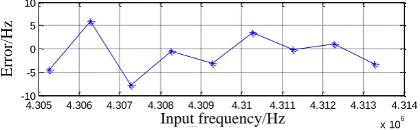
In the same IF and sampling frequency simulation of a single satellite IF signal, the satellite signal simulation, C/A code phase, carrier Doppler shift, signal to noise ratio can be set parameters. Mainly used to verify the BASS algorithm to capture the frequency accuracy. In the Doppler frequency range of ± 5KHZ, nine frequency points are randomly selected, and the signal-to-noise ratio of the simulation signal is set to -21dB. The fine frequency error captured by the BASS method is shown in Figure 1. It can be seen that the BASS captured Frequency accuracy can reach 10Hz or less.
4.305 4.306 4.307 4.308 4.309 4.31 4.311 4.312 4.313 4.314
x 106 -10
-5 0 5 10
输入频率/HZ
误差
/H
Z
E
rr
o
r/
H
z
[image:4.595.145.451.274.369.2]Input frequency/Hz
Figure 1. Acquisition frequency error of BASS method.
In the actual signal tracking process, the local advance, lag code before and after the offset distance
d to take five sampling points, with code length of 5 1.023 0.42625
12
. Taking into account the high
sampling rate, if the offset of the threshold to take half the sampling interval (captured after the threshold), when the noise is large, 10ms adjustment may occur once the initial position of the code out of the threshold value to adjust the failure, So take the offset of the threshold for a sampling
interval (1
5d), in order to avoid fuzzy code position, each time the threshold is exceeded, the code to
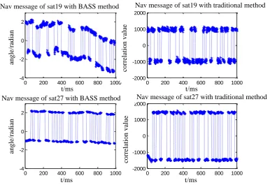
adjust the two sampling points. Acquisition of actual GPS satellite signals, 19,27 two satellite respectively using the BASS method and the traditional phase-locked loop method 1ms long data tracking results shown in Figure 2. The BASS method tracks the phase angle output per millisecond.
Due to the influence of noise and the phase angle range of Equation (2), phase angle 2 flipping
0 200 400 600 800 1000 -4
-2 0 2
19号卫 星BASS方 法 后产 生 的 导 航 电 文 信 息
时 间/ms
相角
/
弧度
0 200 400 600 800 1000 -4
-2 0 2
27号卫 星BASS方 法 后产 生 的 导 航 电 文 信 息
时 间/ms
相角
/
弧度
0 200 400 600 800 1000 -2000
-1000 0 1000 2000
19号卫 星 锁 相 环 法 后 产 生 的 导 航 电 文 信 息
时 间/ms
相关幅
值
0 200 400 600 800 1000 -2000
-1000 0 1000 2000
27号卫 星 锁 相 环 法 后 产 生 的 导 航 电 文 信 息
时 间/ms
相关幅
值
an g le /r ad ia n an g le /r ad ia n c o rr el at io n v al u e c o rr el at io n v al u e
Nav message of sat19 with BASS method Nav message of sat19 with traditional method
Nav message of sat27 with BASS method Nav message of sat27 with traditional method
t/ms t/ms
[image:5.595.110.497.73.338.2]t/ms t/ms
Figure 2. Navigation information output comparison with BASS and traditional second-order phase-locked loop method.
It can be seen from Figure 5 that the BASS method verifies the validity of the BASS method as well as the navigation message information output by the traditional method. The SNR of No. 27 star is higher than that of No. 19 star, the conventional method is reflected in the high relative amplitude, and the BASS method is reflected in the relative phase angle value of the output is relatively compact. At the same time, it can be noted that the BASS output phase angle is continuous or there is a jump, and the absolute value of the phase angle is not important, it depends on the initial sampling point.
Summary
Through the above analysis, BASS method can effectively capture and track satellite navigation signals, and has the following advantages:
(1) The precision of the carrier frequency can reach 10Hz, and the acquisition algorithm is simpler than the traditional correlation algorithm.
(2) The C/A code needs to be generated only once during the tracking process, unlike the traditional phase-locked loop tracking method that needs to regenerate the C/A code every millisecond.
(3) Based on block data processing, the use of phase angle to get the required information, more suitable for software radio ideas.
However, because BASS algorithm is based on a long time data block processing, it is a kind of static data processing method, which is not suitable for the dynamic reception of signals, how to improve it needs to be further studied.
Acknowledgement
This research was financially supported by the National Natural Science Foundation of China (41674037, 41631072, 41704034).
References
[2] Kai Borre,Dennis M.Akos,Nicolaj Bertelsen etal.A Software-Defined GPS and Galileo Receiver (A Single-Frequency Approach)[M]. Boston: Birkhäuser,2007.
[3] Alireza Razavi, Demoz Gebre-Egziabher, Dennis M. Akos. Carrier loop architectures for
tracking weak GPS signals[J]. IEEE Transactions on Aerospace and Electronic Systems, 2008, 44(2): 697-710.
[4] Hongyang Zhang, Luping Xu, Yue Jian, etal. A 2-step GPS carrier tracking loop for urban vehicle
applications[J]. Journal of Systems Engineering and Electronics, 2017, 28(5): 817-826.
[5] Liu Xiaoli, Cheng Dongdong, He Xi, et al. Simulation and Testing of FPLL carrier tracking loops
with high dynamic GPS signals[J]. Geomatics and Information Science of Wuhan University, 2014, 39(11): 1329-1333.
[6] Zhang Yong, FU Jinlin. GPS Carrier Tracking Algorithm Analysis and Simulations[J]. Journal of
Projectiles, Rockets, Missiles and Guidance, 2016, 36(5): 115-118.
[7] Tsui J.B.Y., Stockmaster M.H., Akos D.M. Block adjustment of synchronizing signal(BASS) for
global positioning system (GPS) receiver signal processing[C]. ION GPS, Kansas City, 1997, 637-643.
[8] James Bao-yen Tsui. Fundamentals of global positioning system receivers: a software approach