2170
BEAM POINTING ACCURACY OF PHASED ARRAYS FOR
SATELLITE COMMUNICATION
K CH SRI KAVYA1, SARAT K KOTAMRAJU2#, B. NAVEEN KUMAR3, M. D. N. S. MOUNIKA3, SROTE SINGH3, AJAY SIDDA3
1
Professor and Associate Dean (AR), Department of ECE, K L University, Vaddeswaram, Guntur, AP, India
2
Professor and Dean (P&D), Department of ECE, K L University, Vaddeswaram, Guntur, AP, India
#
Consultant, NOTACHI Elektronik Technologies, Andhra Pradesh, India
3
UG Student, Department of ECE, K L University, Vaddeswaram, Guntur, AP, India Corresponding author: [email protected]
ABSTRACT
Phased arrays are utilized as a part of both radar and communication frameworks. These phased arrays are generally used in most applications because they can cover long distance. Phased array for the most part means an electronically look through arrays. All the more as of late, phased arrays are discovering use in communication frameworks such in satellites, and for ground based SATCOM. A phased array is a system that uses large number of individual antenna components each with phase control. The linear arrangement of components is considered for the array. The phase control permits the pattern of antenna radiation example to be filtered electronically to track targets or to keep up interchanges to sustain link. The capacity to frame different concurrent beams implies that the radar can at the same time track various targets. The beam pointing error lies on different variables i.e. if we are trying to point out the beam in particular direction there may be a very small variation in the beam and this causes the beam pointing error. The pointing error relies on upon utilizing shifters i.e., computerized or analogue, scanning angle, bits utilized for phase shifting and dispersing between the components. Here we are trying to reduce the pointing error in order to steer the beam to the desired angle. The pointing error decreases with increase in number of components, increase in number of bits used for producing phase states and increase in spacing.
Keywords: Analog Phase Shifter, Beam Pointing Error, Digital Phase Shifter, Effects On Bpe, Effects Of Steering Angle, Linear Antenna Array.
1. INTRODUCTION
Early radar frameworks utilized antenna arrays shaped by the blend of individual radiators. For modern applications, the coming of electronically controlled phase shifters has afresh guided consideration regarding array antennas [1]-[3]. The capacity of quickly and precisely changing beams allows various capacities to be performed, interlaced in time or even at the same time. Phased Arrays can be controlled adaptively, especially for side lobe minimization. A phased array antenna contains large number of radiating elements each element has its own phase shifter. Generally phased array antennas are used because they can cover a wide area and give effective performance. In this antenna beams are formed by the constructive (or) destructive interference of the radiating elements so that the resultant beam will be in the required direction. The main lobe will always point towards the increasing
2171 regarding array antennas. The planar array type is considered as a two dimensional arrangement that lie in a plane. These contain only one radiating element and each of the element has its own phase shifter to rotate the beam in the required direction. Capacity of quickly and precisely changing the beam allows various capacities to be performed, interlaced in time or even at the same time.Phased Arrays can be controlled adaptively, especially for side lobe minimization. Phased Arrays are extremely costly. As innovation advances, expenses are decreased, especially in the zones of phase shifters and drivers. In the meantime, the journey for better execution with lower side lobes and wider bandwidth keeps the costs high. This is a territory where hypothesis and comprehension have propelled much. Although there are many types of arranging the arrays with different types of elements, we consider linear arrangement of arrays. Beam is shaped by transforming the phase of the signal that is being transmitted from each antenna, in order to give either the constructive or destructive interference to guide the beam in the sought course. At whatever point we need to scan, track and transmit the signal to a distance particularly in satellite correspondence, the beam pointing error comes into picture, due to this beam pointing error the signal cannot be transmitted in proper angle and the target satellite cannot be detected, we are trying to reduce this pointing error. Phased Arrays are extremely costly [4]. As innovation advances, expenses are decreased, especially in the zones of phase shifters and drivers. In the meantime, the journey for better execution with lower side lobes and wider bandwidth [5-8] keeps the costs high. This is a territory where hypothesis and comprehension have propelled much. Although there are many types of arranging the arrays with different types of elements [9-13], we consider linear arrangement of arrays. Beam is shaped by transforming the phase of the signal that is being transmitted from each radiating element, in order to provide either the constructive or destructive interference to guide the beams in the sought course. At whatever point we need to scan, track and transmit the signal to a distance particularly in satellite correspondence [14], the beam pointing error comes into picture, due to this beam pointing error the signal cannot be transmitted in proper angle and the target satellite cannot be detected, we are trying to reduce this pointing error. So, our principle is to discover the exactness of pointing accuracy of beam as for a few parameters. The parameters are utilizing digital phase shifter, analog phase shifter, analog constant phase shifter, steer angle and separation between the components [15].Factors effecting beam pointing error Beam pointing error can be defined as when we
try to point out a target satellite through some degrees we cannot exactly point out the satellite at that point there will be some deviation of about 0.1 or 0.2 degrees this causes the pointing error. The beam pointing error lies on different variables i.e. if we are trying to point out the beam in particular direction there may be a very small variation in the beam and this causes the beam pointing error. The pointing error relies on upon utilizing shifters i.e., computerized or analogue, scanning angle, bits utilized for phase shifting and dispersing between the components. Here we are trying to reduce the pointing error in order to steer the beam to the desired angle. The pointing error decreases with increase in number of components, increase in number of bits used for producing phase states and increase in spacing. Along these lines, our standard is to find the precision of directing exactness of shaft with respect to a couple of parameters. The parameters are
1. Digital phase shifter
2. Analog phase shifter
3. Analog constant phase shifter
4. Effect of steering angle on phase quantization
.
2. BEAM POINTING ACCURACY USING ANALOG PHASE SHIFTER
A phased array antenna comprises of substantial number of phased shifters for electronic beam directing. Each phase shifter contains electronic circuit that can change the phase of the receiving signal. Presently let us consider the separation between the components of the linear array be presented by ∆c. We needed to send the signal that is checked by an edge of t0. Let us consider the phase
shift between the nearby components is given by
δ ∆c sin (1)
Where
δ = Phase Shift for the nth element. k = Phase Constant ( ).
∆c = Spacing between the elements. nle = Number of elements.
= Steering angle.
2172 us a chance to expect that the space between the components of the similarly dispersed straight receiving wire cluster is equivalent to d, and we need to get a flag originating from the point bearing h0. Accept that electronically controlled phase shifters give a dynamic phase shift between the adjoining receiving wire components∆δ ∆δ so , then
∆δ so k. d. sin so ; δ . . . sin o ;
The linear antenna array factor for the phased array using analog phase shifters [16] can be expressed as
!" #"$%∗ ∗∆'() !" * !" +, -.
!" # ∗∆'() !" * !" +, -. (2)
Where
λ= Wavelength
s = Scanning range varies from to /2
The R.M.S beam pointing error using R.M.S phase error can be calculated as
δΦ
2.3.4 8∆9∗9: √6 7, ∗"$%;/= (3)Where
Σ = R.M.S phase error.
δΦ2.3.4 = R.M.S Beam Pointing Error
It can be obtained by producing the phase states obtained with the phase shift produced for each element in (1) subtracting them with the nearest rounding values and computing R.M.S value for that gives Σ.
3. BEAM POINTING ACCURACY USING
CONSTANT PHASE SHIFTER
We take a gander at first as analog constant-phase shifter, i.e., [17] to steer in the direction the obliged frequency is f0 for the element
ψ
nle=nle*ψ
0 (4) withψ0=
∗
?, ∆c ∗ sin (5)
where
λ is the wavelength at which the frequency f0 occurs.
The phase that weights stay stable with frequency. the array factor can be overlooked as
!" #"$%∗ ∗
∆'
( ) !" *A,= -.
"$%∗ !" # ∗∆'() !" * A,=-.
(6)
Where, let s varies from to .
The R.M.S beam pointing can be figured with the assistance of (3) and toward understand that thing, first we ought to compute phase error. Σ can be ascertained in a similar system specified above for analog phase shifter aside from it contrasts in one thing that phase states got with phase shift created for every element in (4) deducting them with the floor values gives phase error.
4. BEAM POINTING ACCURACY USING
DIGITAL PHASE SHIFTER
Most phase shifters are carefully controlled, so they understand phase shifts with a discrete ∆p equivalent to ∆p ∗CD, where qb is the quantity of bits, and 2bt is the quantity of digital phase shifter phase states. For example, a one-bit (bt=1) digital phase shifter creates just two phases: 00 and 1800, a
two-bit digital shifter can realize four phases
0, , /,6∗ . Furthermore, a three-bit digital phase
shifter can understand phases 0,G, ,6∗G . The function for the array factor is given by (7).
|
s | I
!" #JKL= ∗M∗∆9∗) !" * !" , -.!"#M∗∆'=∗) !" * !" , -.
I
(7)
Where, let s varies from to .
The error in the beam pointing of the multi-element array can be assessed as
δΦ
2.3.4 8 ∗∆9 ∗ OP+ +∆N, ∗ ;/=(8)
2173 the enlightened wave is displayed by semi irregular stage dispersion along the exhibit (for instance, uniform arbitrary stage dissemination in the range (-90° to90°). Such stage dissemination can be created by uncommon nourishing system outline. Arbitrary stages required for the pay of nourishing system stages are put away in the PC memory and don't rely on upon the sweep point exhibits reenactment comes about for the straight cluster component of the radio wire cluster comprising of 132 components under condition that exhibit stage blunder appeared is demolished utilizing arbitrary stages, and an output show straight cluster consider with and without randomizing stage mistake for three-piece stage shifters, d indicate comparable bends for good for nothing stage shifters. As should be obvious, randomizing the intermittent stage blunder fundamentally decreases the parasitic lobes, while expands the normal power sidelobe level.
5. STEERING ANGLE EFFECT
Beam steering is about altering the course of the main lobe of a radiation pattern. The light emission straight array can be directed in edge by changing the relative time delays between the elements or can say, beam steering is about changing the course of the primary projection of a radiation design. In radio frameworks, beam beacon might be refined by redirecting the antenna components [18] or by altering the relative periods. The easiest way is mechanical beam steering, where the antenna is physically mounted in such a way as to lower the point of the signal on one side, regardless this furthermore raises it on the inverse side making it important in just to a great degree compelled conditions. And it can be effectively observed that little components have more beam spreading and thus higher precise vitality content, which van be joined to expand controlling. As component size declines, more components must be kept together to look after sensitivity. In any case, this additionally raises it on the opposite side, making it valuable in just extremely constrained circumstances [19].
Q 9: ∗"$%RS ∗M∗∆'=∗) !" * !" ,-
!" ∗"$%RS ∗M∗∆'=∗) !" * !" ,- (9)
B=1-(S*(Φb,R.M.S) 2
*sin(nle∗k∗∆c∗)sin s sin2 0-)*C (10)
!" ∗"$%RS ∗M∗∆'=∗) !" * !" , - ∗V∗W
4!" M∗∆'=∗) !" * !" ,- (11)
Most stage shifters are carefully controlled, so they understand stage shifts with a discrete ∆ equivalent to
∆ 2//2X , where q is the quantity of bits, and 2q is the quantity of advanced stage shifter stage states. For instance, a one-piece (q=1) advanced stage shifter creates just two stages: 0° Z 180° 0 a two bit digital shifter and a good for nothing computerized shifter can understand four 0 , /, , 3//2.
It is seen that the blunder between the perfect bend and its estimation is a intermittent capacity of the X coordinate. Periodic error cause fundamental lobe lessening, deliver an arrangement of projections called as ''quantization lobes'', and cause blunder in the principle bar guiding position. It is known [28, 29] that the exhibit figure for a direct radio wire array with computerized phase shifters can be exhibited as
AFdigit linear =∑ Q_.∑ In.ej(k.d.sin`-k.d.(sin`0+m2//∆
(12)
where parasitic lobe coefficients Cm are given by
Cm=(-1)m.sin(∆/2 / ∆ π. m (13)
The above formula demonstrates that the exhibit variable of the array with computerized phase shifters is an aggregate of the straight array elements with abundancy weightings and
beam angle directions
`rm= arcsin(ƛ.r/d + (1+2.//∆. m . sinθo (14)
where r, m = 0, ± 1, ± 2 …
An exhibit calculate with m = r = 0 compares to the principle shaft while beams with number md 0 decide undesirable (parasitic or quantization lobes) projections. It is seen that the edge bearings rely on upon the scanning angle `e, and the parasitic projection amplitudes diminish with expanding number m. Basic estimation of the fundamental shaft misfortune impact because of computerized stage shifters is
∆AFlinear j Co !"l∆=m
∆/ (15)
Quantization lobes (QL) values depend just on the
checking angle position and try not to rely on upon
2174 estimation of quantization flap QL (m = 1) is
equivalent [with regard to the main lobe to
QLjnSn 1/ 2.∆ 1 (16)
Where, let s varies from to
The function for the array factor [20] is given by (9).
Where
Φb, R.M.S
2 /2
3∗22op (17)
When the phase errors are arbitrary and not correlated to each other, then the R.M.S beam pointing error is given by
δΦ
2.3.4 8∗∆O∗OP+ +,q √ ∗ RS RS ∗ CD(18)
5. SPACING, COMPONENTS AND BITS
USED
For a uniformly illuminated array, the 3–dB beam width is around
∆theta3ot = q 0.443∗v1 ∗∆cλ (19)
This equation (14) gives the relation between wavelength and theta 3dB beam width and between spacing and theta 3dB beam width. With the help of (12), the R.M.S beam pointing error can be computed as
δΦR.M.S = ∆theta3ot∗1.60
2op√2 v1 (20)
The condition (15) demonstrates the reliance between the R.M.S beam pointing error and number of bits utilized and reliance between the pointing error and number of components utilized [20].
6. RESULTS
2175
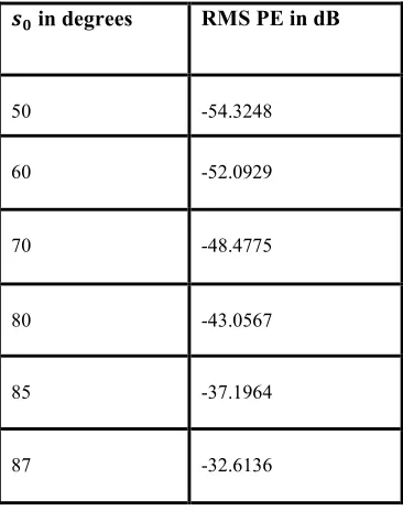
Table 1: Vs R.M.S Pointing error in dB for Analog constant phase shifter with λ/2 spacing and the number of elements=64
{| in degrees RMS PE in dB
50 -54.3248
60 -52.0929
70 -48.4775
80 -43.0567
85 -37.1964
87 -32.6136
Table 2: Vs R.M.S Pointing error in dB for Analog phase shifter with λ/2 spacing and the number of elements=64
{| in degrees RMS PE in dB
50 -60.3669
60 -58.1280
70 -54.8465
80 -48.9299
85 -42.9518
[image:6.612.224.407.127.359.2]2176
[image:7.612.325.491.315.483.2]Figure 1: For analog phase shifter nle=100, frequency=15GHz, ∆} = λ/3 and =10
Figure 2: For analog phase shifter nle=250 ,frequency=14GHz, ∆} = λ/3 and =100\
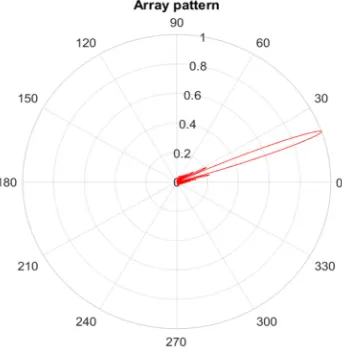
[image:7.612.118.279.321.481.2]Figure 3: For analog phase shifter nle=100, frequency=15GHz,∆} = λ/3 and =300\
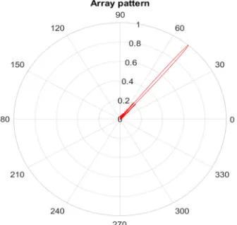
[image:7.612.127.276.526.683.2]Figure 4: For analog phase shifter nle=250, frequency=15GHz, ∆} = λ/3 and =500\
Figure 5: For analog constant phase shifter nle=100, frequency=15GHz, ∆} = λ/3 and =00\
[image:7.612.324.482.533.680.2]2177
[image:8.612.345.516.319.496.2]Figure 7: For analog constant phase shifter nle=100, frequency=15GHz, ∆} = λ/3 and =200\
Figure 8: For analog constant phase shifter nle=50, frequency=13GHz, ∆} = λ/3 and =500
Figure 9. For analog constant phase shifter nle =70, frequency=13GHz, ∆} = λ/3 and =700
[image:8.612.121.278.330.492.2]Figure 10: For digital phase shifter nle=50, frequency = 14GHz, ∆} = λ/4 and =00
[image:8.612.124.273.533.682.2]Figure 11: For digital phase shifter nle=50, frequency = 14GHz, ∆} = λ/4 and =200
[image:8.612.353.519.549.690.2]2178
Figure 13: For digital phase shifter nle=50, frequency = 14GHz, ∆} = λ/4 and =850
Figure 14: For digital phase shifter nle=150, frequency=14GHz, ∆} = λ/4 and =500
[image:9.612.100.524.69.251.2]Figure 15: The variation of beam pointing error in dB with varying number of bits and the scanning angle
[image:9.612.348.516.291.450.2]Figure 16: For effect of steering angle with nle=50, frequency=16 GHz, ∆} = λ/8 and =25
[image:9.612.121.279.311.464.2]Figure 17: For effect of steering angle with nle=150, frequency=16 GHz, ∆} = λ/8 and =500
Figure 18: The variation in the R.M.S beam pointing error with varying the separation between the elements and scan
[image:9.612.94.540.500.691.2]2179
Figure 19: The variation in the R.M.S pointing error with varying the separation of the elements and the scan angle
with nle=3
Figure 20: The variation in the beam pointing error computed in dB with bits being altered
Figure 21: The variation in the beam pointing error computed in dB with bits altered each time comprising of
elements =100
Figure 22: The variation in the beam pointing error computed in dB with bits altered each time comprising of
elements =100 and spacing λ/1
Figure 23: The variation in the beam pointing error computed in dB with bits altered each time comprising of
elements =100 and spacing λ/7
2180 7. CONCLUSION
We can conclude from the graphs plotted that simple analog phase shifters give better and effective performance over analog constant phase shifters with respect to the beam pointing accuracy inferred from the table mentioned in result i.e. For analog phase shifter the beam pointing error is less when compared with the analog constant phase shifter. When going to digital phase shifters, the accuracy depends on the number of bits utilized for producing phase shift and with increasing components, we can have the summon over the beam pointing accuracy. If the number of components is more, the principal lobe points towards the craved steering angle precisely and the side lobes are minimum. Considering the scope of array, the steering angle decides the inaccuracy. The separation between the components influences the precision, as the accuracy decreases with increase in separation. The main disadvantage is if more number of antennas re used then the whole structure will be difficult to handle and cost also increases. We can conclude that beam pointing error will be minimum when the elements are more, the spacing between the elements is less and the number if bits are more.We can also say from the graphs that if the side lobes are minimum then the pointing error will be less so that we can point out the target satellite accurately.
ACKNOWLEDGEMENTS
The authors especially thank the support given from Department of Science and Technology (DST), Government of India through the funded project with F. No: SB/FTP/ETA-0175/2014. The authors also thank the management of KL University for supporting and encouraging this work by providing the facilities in Centre for Applied Research in Electromagnetics (CARE) of ECE.
REFERENCES
[1] Robert C Hansen (2009) Phased array antennas, 2nd edn. Wiley, New York
[2] MaillouxR.J., “Phased Array Antenna Handbook”, Artech House Inc. 1994.
[3] H. J. Visser “Array and Phased Array Antenna Basics”, Jon Wiley & Sons Ltd, 2005.
[4] Kavya, K. Ch Sri, Sarat K. Kotamraju, and Habibulla Khan. "Calibration of linear array antenna using restoration technique with near-field compressed sensing." Antennas and Propagation (EuCAP), 2013 7th European Conference on. IEEE, 2013.
[5] B.T.P.Madhav, VGKM Pisipati1, Habibulla Khan, V.G.N.S Prasad, K. Praveen Kumar, KVL Bhavani and M.Ravi Kumar, “ Liquid Crystal Bow-Tie Microstrip antenna for Wireless Communication Applications”, Journal of Engineering Science and Technology Review ISSN: 1791-2377 , 4 (2) (2011) 131-134. [6] B.T.P.Madhav, VGKM Pisipati1, Habibulla
Khan, V.G.N.S Prasad, K. Praveen Kumar, KVL Bhavani and M.Ravi Kumar, “Liquid Crystal Bow-Tie Microstrip antenna for Wireless Communication Applications”, Journal of Engineering Science and Technology Review ISSN: 1791-2377 , 4 (2) (2011) 131-134. [7] B.T.P. Madhav, S.S. Mohan Reddy, J.
Ravindranath Chowdary,V. Vinod Babu, S.S. Satya Parthiva, S. Kalyana Saravana, “Analysis of Dual Feed Asymmetric Antenna”, International Journal of Applied Engineering Research, ISSN 0973-4562 Volume 8, Number 4, June-2013, pp. 361-367.
[8] B.T.P.Madhav, S. S. Mohan Reddy, Bandi Sanjay, D.Ujwala, “Trident Shaped Ultra Wideband Antenna Analysis based on Substrate Permittivity”, International Journal of Applied Engineering Research, ISSN 0973-4562, Volume 8, Number 12, Nov-2013, pp. 1355-1361.
[9] B T P Madhav, Krishnam Naidu Yedla, G.S.,
Kumar, K.V.V., Rahul, R., “Fractal aperture
EBG ground structured dual band planar slot antenna”, International Journal of Applied Engineering Research, ISSN 0973-4562, Volume 9, Number 5, Jan-2014, pp 515-524.
[10]B. T. P. Madhav, Mounika Sanikommu, M. N. V. S. Pranoop, K. S. N. Manikanta Chandra Bose and B. Sriram Kumar, CPW Fed Antenna for Wideband Applications based on Tapered Step Ground and EBG Structure, Indian Journal of Science and Technology, ISSN: 0974-6846, Vol 8, Issue 9, May 2015, pp 119-127
2181 [12]B T P Madhav, K V V Kumar, A V Manjusha, P
Ram Bhupal Chowdary, L Sneha, P Renu Kantham, “Analysis of CPW Fed Step Serrated Ultra Wide Band Antenna on Rogers RT/Duroid Substrates”, International Journal of Applied Engineering Research, ISSN 0973-4562, Volume 9, Number 1, Jan-2014, pp. 53-58
[13]B T P Madhav, K V V Kumar, A V Manjusha, P Ram Bhupal Chowdary, L Sneha, P Renu Kantham, “Analysis of CPW Fed Step Serrated Ultra Wide Band Antenna on Rogers RT/Duroid Substrates”, International Journal of Applied Engineering Research, ISSN 0973-4562, Volume 9, Number 1, Jan-2014, pp. 53-58
[14]V. Weerackody and L. Gonzalez, “Performance of satellite communications on the move systems in the presence of antenna pointing errors,” in Proc. Mil. Commun. Conf., 2006, pp. 1–7
[15]B T P Madhav, A Manikanta Prasanth, Sreeramineni Prasanth, Batchu Mohan Sai Krishna, Devani Manikantha, Usirika Sharmila NagaSai, "Analysis of defected ground structure notched monopole antenna." ARPN Journal of Engineering and Applied Sciences, ISSN 6608.10 (1819): 2.
[16]Rabinovich, Victor, and Nikolai Alexandrov. Antenna arrays and automotive applications. Springer Science & Business Media, 2012.
[17]Clenet, Michel, and Gilbert A. Morin. "Visualization of radiation-pattern characteristics of phased arrays using digital phase shifters." IEEE antennas and propagation magazine 45.2 (2003): 20-35.
[18]Kumar, K. Prabhu, et al. "Uniplanar Quasi-Yagi Antenna for channel measurements at X-band." Journal of Theoretical and Applied Information Technology 26.2 (2011): 35-39. [19]R. W. Huggins, P. T. Heisen, G. E. Miller, D. I.
McMeen and K. L. Perko, “Phased Array Transmit for a Satellite,” 1999 /EEE Antennas and Propagation Society
[20]Brock, Billy C. The application of taylor weighting, digital phase shifters, and digital attenuators to phased-array antennas. No. SAND2008-1687. Sandia National Laboratories, 2008.