Design and Implementation of Autonomous Surface
Vehicle
Gakwaya Achille1, Anisha K2, Kiran MV3, Meghana R4, Dr.Hariprasad S A5 1,2,3,4
Electronics and Communication Engineering Department, Jain University
5
Professor, Director, School of Engineering and Technology, Jain University
Abstract: Accurate ship navigation is very essential for saving fuel as well as time. In order to achieve accurate tracking in Autonomous Ship navigation various controllers like PD, PID, Predictive and Adaptive controllers are used. In this work we design an autonomous system using PID controller to increase tracking efficiency. PID was chosen because it allows real-time implementation of an Autonomous Surface Vehicle. The work started with the implementation of supporting hardware like Brushless DC Motors, ESC for BLDC motors speed control. We then later interfaced GPS and Compass and Telemetry to check for the working of our system by giving waypoints and observe the course tracking. With the Implementation of PID along with all the above we get bet better tracking efficiency and computation is faster.
Keywords: BLDC, Pixhawk, ESC, Telemetry, PID
I. INTRODUCTION
An Unmanned vehicle is one which controls itself without the need of human assistance on board. They can be remote controlled, remote guided or autonomous vehicles. Autonomous vehicles are increasingly used in civilian and military applications such as rescue, search and data collection. They are of different types, namely aerial, ground, surface and underwater.
The main requirement is autonomy i.e., the capability of the system to act on its own and still react properly to external factors that may arise. In our discussion we mainly concentrate on Autonomous Surface Vehicle because there is scope for improvement in this area. Parameter. The main objective of this project is to build a prototype of an Autonomous Surface Vehicle using Pixhawk as the master controller. The Autonomous Surface Vehicle is used to reach the desired destination without any human interference, hence providing accurate tracking with minimum errors.
II. PROBLEMSTATEMENTANDOBJECTIVE
A. Problem Statement
Ship technology has evolved over the past decades. However, there are still challenges which are on -time arrival at destination, accurate tracking and fuel consumption, to name a few. That’s why we needed to build an efficient closed loop, Autonomous Surface Vehicle to reach the desired destination within the predicted time and with minimum errors by using a PID controller.
B. Objective
1) To increase the accuracy in course tracking 2) To save time to go from source to destination 3) To do surveillance using the ship
III.LITERATURESURVEY
The parameters of Adaptive controllers can change in accordance with the disturbances in the sea. But the computations involved are very intense and these controllers are not able to act according to future outcomes predicted [1].
Modelling and identification of autonomous surface vehicle was published where we observed sensors used were GPS and Compass for designing the model. Experimental results revealed that linear motion of vehicle was measured using GPS [2] the sway motion of using sensors failed and confirmed the failure of linear drag model.
Performance Analysis of Ship Tracking using PID/Predictive Controller was published where we understood the efficient ship tracking by giving waypoints [3]. The time required for computations using predictive controllers increases as waypoints and prediction steps are increased. This can be minimized by the use of matrix inversion method [4].
IV.PROPOSEDSYSTEM
The ship designed should accurately track its course by means of waypoints set using GPS. The PID closed loop control helps to increase the accuracy in tracking. Different hardware work together to make the ship autonomous.
[image:2.612.178.444.160.404.2]A. System Architecture
Figure 1. System Architecture
The above figure shows how our system is interconnected, the central processor is Pixhawk, an advanced autopilot system which integrates two advanced processors STM32F103. Next is the actuator part which consists of a pair of BLDC motors and ESCs to provide propulsion and allow steering of the ship. GPS and Compass are used to provide accurate course and tracking., Telemetry allows us to communicate with the processor wirelessly. Lastly, the remote system consists of an RC transmitter and receiver, the latter which is interfaced to Pixhawk and allows us to give commands directly via the transmitter.
B. Hardware Required 1) DC Motors
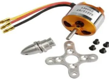
[image:2.612.211.391.554.685.2]DC motors are mainly used to make the ship move or stop. They do it by converting electrical energy into rotation of their shafts. The motor’s shaft is connected to a propeller which rotates in the water to give a thrust. In our project we used 2200kv brushless type of DC motors because of their durability, reliability and smooth operation.
2) ESC
Figure3. ESC
An electronic speed controller (ESC) is used to control the BLDC motor’s speed and to perform brakes. ESCs are motor drivers which provide the current rates required to rotate the motors. The ESC used is 30A BLDC ESC.
3) Transmitter
Figure4. Transmitter
The AV-RCB7X Transmitter is used to send some radio signals to control speed of the motors, throttle as well as switch from manual to autonomous mode of the ship.
4) Receiver
The AV-RZ7 Receiver is used to demodulate the radio signals so that they can be interpreted by the processor and hence perform a particular task.
5) Telemetry
Figure5. Telemetry
A 455mhz telemetry is used to communicate with the processor wirelessly. Telemetry helps in sending commands used for calibration of the different hardware used on the ship as well as setting waypoints to the ship remotely.
6) GPS
Figure 6. GPS
The GPS model used is the NEO M8 GPS module. It is used to get accurate position and help in course tracking by using waypoints set.
[image:4.612.116.504.470.630.2]C. System Design
Figure 7. The ship
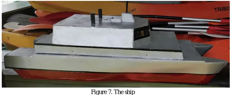
The ship design was made by using balsa wood. It involves several steps of design which start with the design of bulkheads and keel using the balsa wood, followed by other steps like profile covering, fining process, primer method followed by varnishing and painting. After all these steps we obtained the ship which is shown in figure 7. After this all the hardware components were placed onboard and calibrated. The firmware and other necessary codes were written on the processor. Next, we set waypoints by means of mission planner software.
The results obtained were very interesting. The ship was able to track its course accurately with minimum errors. However, more implementations should be done to make the ship fully autonomous, for example there is need to implement obstacle detection and avoidance system on the ship. This can enable the ship to avoid obstacles during its course. Furthermore, in extreme disturbances, one has to incorporate a well-designed side thruster system which make the ship come back to its course when veered away by disturbances. The PID algorithm was used to keep the system in a closed loop and hence correct the errors that arise during course tracking.
REFERENCES
[1] S.A. Hariprasad, Pampapathi, Vijay Singh Dr.KrishnaSharath.K, Smt.T.D.Shashikala, “A Design Approach to Rudder Controller”, international journal of computer science and technology (IJCST)- IJCST Vol. 3, Issue 3, July - Sept 2012
[2] M. Caccia, G. Bruzzone, R. Bono, "A practical approach to modeling and identification of small autonomous surface craft", IEEE Journal of Oceanic Engineering, vol. 33, no. 2, pp. 133-145, April 20
[3] HanlinNiu, Yu Lu, Al Savvaris, AntoniosTsourdos,"Efficient Path Planning Algorithms for Unmanned Surface Vehicle", IFAC-PapersOnLine, vol. 49, pp. 121, 2016, ISSN 24058963.
[4] Hariprasad, Dr. M. Krishna, Cdr.Vijay Singh, PampapathiSanjay. N, Arunlal.K.S “Performance Analysis of Ship Tracking using PID/Predictive Controller”.Vol 1,No 1(2013): June,Internation Journal of Science Engineering and Advance Technology,ISSN:2321-6905.