Development of Steel Surface Composite by
Friction Stir Processing
Mr. S. Gain1, Dr. S. Aravindan2 1
Student, 2Professor, Department of Mechanical Engineering, Indian Institute of Technology Delhi.
Abstract: Friction stir processing (FSP) is a solid-state process where the material within the process zone undergoes intense plastic deformation resulting in dynamically recrystalized grain. FSP structure has smaller grain size, low porosity level and improved mechanical properties. By this process hardness of produced composite surfaces is improve more compared to that of Parent metal. Today steel is one of the most common materials in the world. It is a major component in buildings, infrastructure, tools, ships, automobile machines and weapons. That’s why the main focus on this work is to improve mechanical properties of steel through FSP. Conventional vertical milling machine, capable of withstanding the forces generation during processed and having a powerful spindle motor to generate torque needed for friction stir processing was selected for the purpose. Essentially trial runs were conducted to develop the correct processing procedure for obtaining defect free processing. Metallurgical testing was carried out using Macro-hardness testing, microstructure examination. Macro-hardness in the process zone and the heat affected zone were found to be more than the base material.
Keywords: FSP, Hardness, Microstructure, Tensile strength.
I. INTRODUCTION
Friction stir processing (FSP) is a new solid-state processing technique that can be used for surface hardening through microstructural modification. This process is a modification of the friction stir welding (FSW) process used for solid state joining of two separate pieces of metallic materials. Basically, FSP involves the use of a non-consumable rotating tool with a pin and shoulder inserted into a single piece of material and traversed along the desired path to cover the region. This action results in significant microstructural changes in the processed zone as a result of severe plastic deformation, mechanical mixing and thermal exposure of the material. The characteristics of FSP have led to several applications for microstructural modification in metallic materials, including enhanced superplasticity, surface composite, homogenization of nanophase alloys, metal matrix composites and microstructural refinement of cast alloys.. Friction stir processing can be applied as a single-pass for processing a small area. For large engineering components in which the contact areas are relatively large, single pass FSP may not be adequate. In such cases, multi-pass FSP with a layer of components is reinforced by ceramic phases while the bulk of components retain the original composition and structure with higher toughness. Friction Stir Processing (FSP) was attempted to incorporate ceramic particles into surface layer of steel alloy to form surface composite. The aim of this work is to investigate the possibility of incorporating ceramic particle into surface layer of steel to form surface composite by means of FSP technique.
II. EXPERIMENTAL PROCEDURE
The basic concept of FSP is a non-consumable tool comprising a shoulder and pin rubs against the work material and produces enormous frictional heat. The heat, combined with deformation by the stirring action of tool pin and pressure due to tool shoulder, produces a defect-free, recrystallized, fine-grained microstructure. Two parameters are very important for FSP, tool rotation rate (ω, rpm) in clockwise or counterclockwise direction and tool traverse speed (v, mm/min) along the line of processing. The rotation of tool results in stirring and mixing of material around the rotating pin and the translation of tool moves the stirred material from the front to the back of the pin and finishes FS process. Higher tool rotation rates generate higher temperature because of higher friction heating and results in more intense stirring and mixing of material.
A. Tool Fabrication
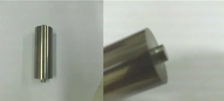
[image:2.612.89.523.196.393.2]Tool Fabrication is the most influential aspect of process development. The tool geometry plays a critical role in material flow and in turn governs the traverse rate at which FSP can be conducted. An FSP tool consists of a shoulder and a pin as shown in Fig 2.1. In the initial stage of tool plunge, the heating results primarily from the friction between pin and workpiece. Some additional heating results the deformation of material. The friction between pin and work piece results in biggest component of heating. From the heating aspect, the relative size of pin and shoulder is important and the other design features are not critical. The shoulder also provides confinement for the heated volume of material. The second function of the tool is to ‘stir’ and ‘move’ the material. The uniformity of microstructure and properties as well as process loads is governed by the tool design. The dimension of the tool used in this study are presented in table 2.1
Figure 2.1 Tool with shoulder and pin.
Table 2.1.Tool dimensions
B. Process parameter
One of the most important work to study the effect of the processed parameters on development of the composite surface. The processed parameters commonly mentioned in here are tool traversed speed, tool rotational speed, tilt angle.
This is one of the most important parameter that has drawn the interest of researchers working in the area of friction stir processing. Processing speed along with tool RPM decided whether enough heat input is being supplied to the processed which is favorable to develop the metallurgical and mechanical properties. Processing speed lower than 100mm/min, generate excessive heat and the processed made slow. If the processing speed is high the peak temperature is not reached up to recrystalization temperature because for that appeared the defect formation. Thus for performing the experiment the speed selected 100mm/min, 125mm/min and 160mm/min is shown in table 2.1.The another importance parameter for friction stir processing. Most of the researchers have tried to vary it to improve the mechanical properties of the friction stir processing. Tool RPM is deciding the amount the heat generation during the processed. Tool rotation above 710 RPM generates excessive heat cause of that tool got deformed and partially sheared. Less than 450 tool RPM heat generation is very less and the work material did not soften properly. For this the experimentation tool RPM were selected 450 RPM, 560 RPM and 710 RPM is shown in table2.2
Other important parameter is suitable tool tilt angle. Tilt angle is given toward the traveling direction of processing. Researchers specify the value of tilt angle range within 1-3o for this experimentation tool tilt angle was selected 3o is shown in table 2.2
Tool material Tungsten carbide
Shoulder diameter(d) 20mm
Pin diameter(d1) 5mm
Selected processed parameters for this work is shown in table 2.2 Process speed
(mm/min)
Tool rotational speed (rpm)
Tilt angle (degree)
100 450 3
100 560 3
125 560 3
160 560 3
160 710 3
III. EXPERIMENTAL WORK
Experiments were carried out in a vertical milling machine made by Bharat fritz Werner Ltd. Vertical milling machine can be used as a position control friction stir processing machine. It consists of a vertical spindle on to which the tool is mounted with the help of a collate. The tool can be brought in a contact with the workpiece by lifting the machine table and it can be moved in both vertical and horizontal axis .The plate to be processed can be fixed on the machine table by clamping. The machine can be set to range of weld speeds (31 to 1600mm/min) and spindle speeds (45 to 1800 RPM).The machine is powered by an 11 KW/15HP three phase induction motor. Most of the requirements of friction stir processing are satisfied by a vertical milling machine that is why researchers have used vertical milling and modified vertical milling machine for friction stir processing.
A. FS processing Without Particles
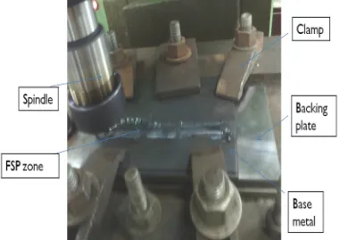
Prior to processing, the backing plate was ground and working plate surface was cleaned with acetone. The plate was clamped tightly with backing plate, before processing the tool rotational speed was set to the desired value. The traverse speed was manually controlled in order to avoid high stresses on the tool. Three degree tilt angle was given. Frictional heating is produced from the rubbing of the rotating shoulder with the workpiece, while the rotating pin deforms and stirs the locally heated material. FSP is considered to be a hot working process where severe plastic deformation occurs within the FS processed sheet. FS processed zone is characterized by
[image:3.612.117.498.440.709.2]dynamic recrystallization which results in grain refinement, and homogenous, equiaxed grain structure. Figure 3.1 shows the experimental setup of FS processing without particles. Typical process parameters of FSP are presented in table 2.1.
B. FS processing with B4C particles
Friction stir processing (FSP) was employed for the fabrication B4C composite surface layer on steel plate. Commercially available
B4C micro particles was added into a small amount of methanol and then the B4C powder was filled into a groove (depth of
1mm×width of 2 mm) on the steel plate before the FSP was carried out. The tool was inserted into the groove filled with the B4C
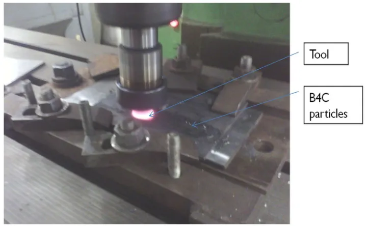
powder. The tool tilt angle of 3◦was used during processing. Figure3.3 shows the experimental setup of FS processing with B4C
[image:4.612.97.511.157.293.2]particles.
Figure.3.2. Plate used in FSP with B4C Grooves (depth of 1mm×width of 2 mm) made on the steel plate
Figure 3.3Processing with B4C particles
IV. RESULT AND DISCUSSION
A. Macro Hardness testing
Leica’s vicker macro hardness tester was used to measure the macrohardness of the different samples, unaffected base metal, heat effected zone of processed metal and heat effected zone of processed metal with B4C. The hardness were measured alone the centre
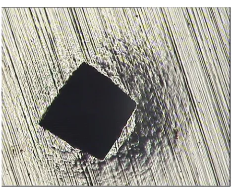
line of the process horizontally from one end to the other. A total of 13 indentations 1.5 mm apart were made covering 20mm processed zone for all the processing condition. During making indentation on samples, load was taken 10kg. Indentations were taken on polished surface (prior to etching) so that the indentions are very clear for accurate measurements of the diagonals. Care
[image:4.612.125.486.319.541.2]Figure 4.1.1 indentation produced on an uneatched surface
Hardness is resistance of material to plastic deformation caused by indentation and it gives indication about the strength of the material. The load on the Vickers macro-hardness indenter usually ranges from a few grams to several kilograms. The indentations should be as large as possible within the confines of sample geometry to minimize errors in measuring the indentation. Vickers hardness is also sometimes called Diamond Pyramid Hardness (DPH) owing to the shape of the indenter. Leica’s vicker macro hardness machine was used to measure the macro-hardness of the different samples base metal, heat effected zone of processed metal without B4C and heat effected zone of processed metal with B4C.
The hardness were measured alone the centre line of the process horizontally from one end to the other. Indentations were taken on polished surface so that the indentions are very clear for accurate measurements of the diagonals. Hardness was measured transverse section of the three different samples. In most of the cases increase in hardness values was observed in processed zone. The hardness value in the FS processed specimens with B4C particles is higher than that of the base metal. This is because of (1)
dispersion of the B4C particles as a harder phase in the steel (2) Severe grain refinement with respect to the base metal and (3)
quench hardening resulted from different thermal contractions between the B4C particles and the matrix.
In the transverse section the hardness values were found around 193HV in the base metal. The processing zone entitled constantly very high hardness at the processed area. After FS processed the average macrohardness value was found around 223HV and after processing with B4C themacrohardness value was found to be 487HV at processing speed of 100mm/min, tool RPM of 450. Figure
[image:5.612.189.423.70.261.2]4.1.1 shows the hardness profile across the processed zone.
Table 4.1.1Vicker’s hardness dataat processing speed of 100mm/min, tool RPM of 450 Distance from centre Vickers Hardness No of
base metal
Vickers Hardness No of FS Processing without particles
Vickers Hardness No of FS processing with B4C particles
-9 170 200 348
-7.5 192 233 317
-6 180 210 421
-4.5 175 235 399
-3 167 276 483
-1.5 185 264 542
0 173 289 486
1.5 181 240 550
3 168 219 407
4.5 193 206 488
6 161 189 354
7.5 172 199 349
Figure 4.1.1 Result of the Hardness taken on the traverse section (at processing speed of 100mm/min, tool RPM of 450)
The processing zone entitled constantly very high hardness at the processed area. After FS processed the average macrohardness value was found around 251 HV and after processing with B4C themacrohardness value was found 376 HV at processing speed of
[image:6.612.58.555.313.716.2]100mm/min, tool RPM of 560. Figure 4.1.2 shows the hardness profile across the processed zone.
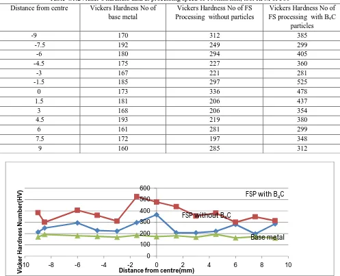
Table 4.1.2Vicker’s hardness dataat processing speed of 100mm/min, tool RPM of 560
Distance from centre Vickers Hardness No of
base metal
Vickers Hardness No of FS Processing without particles
Vickers Hardness No of FS processing with B4C
particles
-9 170 312 385
-7.5 192 249 299
-6 180 294 405
-4.5 175 227 360
-3 167 221 281
-1.5 185 297 525
0 173 336 478
1.5 181 206 437
3 168 206 354
4.5 193 219 380
6 161 281 299
7.5 172 197 348
9 160 285 312
Figure 4.1.2 Result of the Hardness taken on the traverse section (at processing speed of 100mm/min, tool RPM of 560).
0 100 200 300 400 500 600
-10 -8 -6 -4 -2 0 2 4 6 8 10
V
ic
k
er
H
ar
d
n
es
s
N
u
m
b
er
(
H
V
)Distance from centre (mm)
FSP with B4C
FSP without B4C
base metal 0 100 200 300 400 500 600
-10 -8 -6 -4 -2 0 2 4 6 8 10
V ic ke r H a rd n e ss N u m b e r( H V )
Distance from centre(mm)
FSP with B4C
FSP without B4C
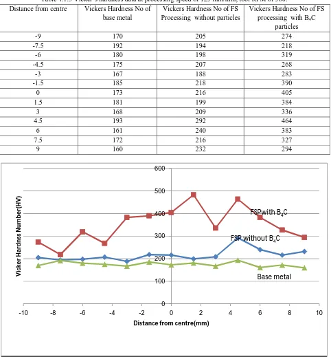
The processing zone entitled constantly very high hardness at the processed area. After FS processed, the average macrohardness value was found around 216 HV and after processing with B4C the average macrohardness value was found 350HV at processing
[image:7.612.67.549.134.653.2]speed of 125mm/min, tool RPM of 560. Figure 4.1.3 shows the hardness profile across the processed zone.
Table 4.1.3 Vicker’s hardness dataat processing speed of 125 mm/min, tool RPM of 560. Distance from centre Vickers Hardness No of
base metal
Vickers Hardness No of FS Processing without particles
Vickers Hardness No of FS processing with B4C
particles
-9 170 205 274
-7.5 192 194 218
-6 180 198 319
-4.5 175 207 268
-3 167 188 283
-1.5 185 218 390
0 173 216 405
1.5 181 199 384
3 168 209 336
4.5 193 292 464
6 161 240 383
7.5 172 216 327
[image:7.612.63.549.136.632.2]9 160 232 294
Figure 4.1.3 Result of the Hardness taken on the traverse section (at processing speed of 125mm/min, tool RPM of 560).
The processing zone entitled constantly very high hardness at the processed area. After FS processed, the average macrohardness value was found around 240 HV and after processing with B4C themacrohardness value was found to be 360 HV at processing
speed of 160mm/min, tool RPM of 560. Figure 4.1.4 shows the hardness profile across the processed zone.
0 100 200 300 400 500 600
-10 -8 -6 -4 -2 0 2 4 6 8 10
V
ic
ke
r
H
ar
d
n
ss
N
u
m
b
e
r(
H
V
)
Distance from centre(mm)
FSPwith B4C
FSP without B4C
Table 4.1.4 Vicker’s hardness dataat processing speed of 160mm/min, tool RPM of 560 Distance from centre Vickers Hardness No of base
metal
Vickers Hardness No of FS Processing without particles
Vickers Hardness No of FS processing with B4C particles
-9 170 183 306
-7.5 192 191 322
-6 180 279 287
-4.5 175 210 450
-3 167 175 498
-1.5 185 306 383
0 173 276 464
1.5 181 281 409
3 168 292 413
4.5 193 285 306
6 161 202 289
7.5 172 185 289
9 160 212 270
Figure 4.1.4 Result of the Hardness taken on the traverse section (at processing speed of 160mm/min, tool RPM of 560).
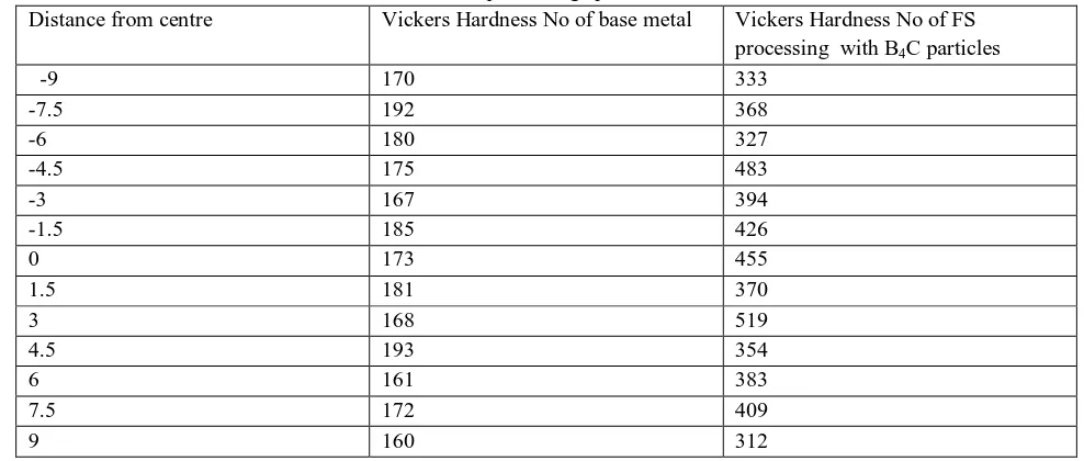
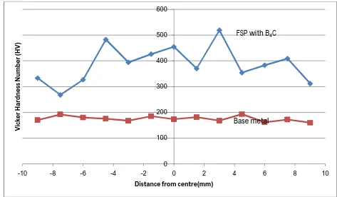
The processing zone entitled constantly very high hardness at the processed area. After processing with B4C themacrohardness
[image:8.612.57.551.528.738.2]value was found to be 387 HV at processing speed of 160mm/min, tool RPM of 710. Figure 4.1.5 shows the hardness profile across the processed zone.
Table 4.1.5 Vicker’s hardness dataat processing speed of 160mm/min, tool RPM of 710.
Distance from centre Vickers Hardness No of base metal Vickers Hardness No of FS
processing with B4C particles
-9 170 333
-7.5 192 368
-6 180 327
-4.5 175 483
-3 167 394
-1.5 185 426
0 173 455
1.5 181 370
3 168 519
4.5 193 354
6 161 383
7.5 172 409
9 160 312
0 100 200 300 400 500 600
-10Vicke -8 -6 -4 -2 0 2 4 6 8 10
r H ar d n e ss N u m b er (H V )
Distance from centre(mm)
FSP with B4C
FSP without B4C
Figure 4.1.5 Result of the Hardness taken on the traverse section (at processing speed of 160mm/min, tool RPM of 710).
B. Optical Microscopy
Different aspects of the microstructure of FS processed steel were studied. The studied features included grain structure and grain size. The process exhibits several distinct microstructural region i.e. processed zone (PZ) and the heat affected zone (HAZ).There is a reduction in grain size from base metal to processed zone. This is because of the dynamically recrystallization happening in processed zone because of friction heat and plastic share. In heat affected zone, there is no much reduction in grain size. Very fine grain of austenite is formed by the processed of dynamically recrystalizaion. The fine recrystallized grains of austenite transform back into ferrite when the temperature falls down. The processed parameters also affected the rate of cooling and the subsequent Austenite→ferrite transformation. The microstructure of the base metal at 500x magnification is shown in figure 4.2.1.
(a) (b)
Figure 4.2.1 Microstructure of base metal (500 x magnifications).
The microstructure of processed zone and heat effected zones of the FS processed without B4C specimens at 500x, 200x
magnification is shown in figure 4.2
0 100 200 300 400 500 600
-10 -8 -6 -4 -2 0 2 4 6 8 10
V
ic
ke
r
H
ar
d
n
es
s
N
u
m
b
e
r
(H
V
)
Distance from centre(mm)
FSP with B4C
(a) (b)
Figure 4.2.2 microstructure of FS processed without B4C specimens at500x, 200X magnification (a- PZ and b- PZ and HAZ).
It is evident that B4C particles were uniformly distributed in steel and no discernible porosities and defects were detected. The
surface composite layer was well bonded to steel and no defects were visible. The microstructural features clearly indicate that FSP is very effective technique to fabricate surface metal matrix composite with well-distributed particles.Figure 4.3shows that the B4C
particle led the grain to be refined by the FSP through a recrystallization process. The grain size in the B4C particles in processed
region was clearly fine compared with that of the region without the B4C particles. Figure 4.2.3showing the microstructure of FS
processed specimens with micro sized B4C particles, respectively exhibit that the grain size decreases significantly by increasing the
[image:10.612.162.451.373.598.2]micro-sizes B4C particles.
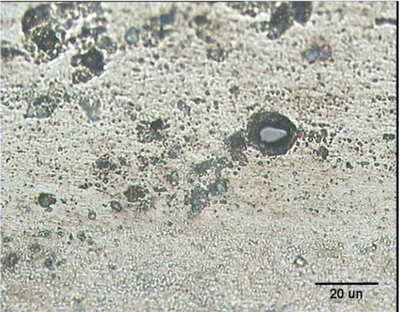
Figure 4.2.3 microstructure of processed specimen with B4C at 500 x magnifications.
C. Scanning Electronic Microscopy
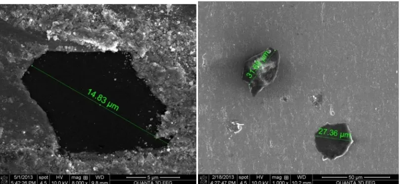
A scanning electron microscope (SEM) is a type of electron microscope that produces images of a sample by scanning it with a focused beam of electrons. The electrons interact with electrons in the sample producing various signals that can be detected and that contain information about the sample's surface topography and composition. The electron beam is generally scanned in a raster scan pattern and the beam's position is combined with the detected signal to produce an image. SEM can achieve resolution better than one nanometer. Specimens can be observed in high vacuum, low vacuum and in environmental SEM specimens can be observed in wet condition. The SEM macrograph taken from the cross-section of process zone of FS processed specimens with B4C
Figure 4.3.1 Microstructure of FS processed specimen with B4C by SEM.
V. CONCLUSIONS
A. Friction stir processing of steel has been successfully carried out and it has been demonstrated that friction stir processing results in better mechanical and metallurgical properties as compared to base metal
B. Tungsten carbide can work satisfactorily as a tool material for friction stir processing of steel. The tool can work well without failure. It is important to choose the correct grade of tungsten carbide for making tool
C. Friction stir processing shows three distinct microstructures namely the processed zone heat affected zone and the unaffected base metal.
D. The mechanism of microstructural evolution during friction stir processing of steel starts with the formation of small grains of austenite and this is followed by transformation of these fine austenite grains into ferrite and pearlite.
E. The values of macrohardness in the processed specimens are higher than that of base metal, for all combination of process parameters. Though the hardness values vary within the processed zone, and with process parameters, they never fall below the base metal hardness values. The values of macrohardness in FS processed specimens with B4C particles are larger by two times
than that of the base material.
F. Processing speed at 100mm/min, tool rpm 560 is suitable for FS processing without B4C and for FS processing with B4C
100mm/min, tool rpm 450 is suitable.
G. FS processed composite surface has been studied through optical microscope and scanning electronic microscope and conforming the B4C particles to make composite surface.
REFERENCES
[1] Aldajah S, Ajayi O.O., Fenske G., Trans. ASME, J. Tribol. (2009) Effect of friction stir processing on the tribological performance of high carbon steel 350– 355.
[2] Asadi P., Givi, M.K.B., 2009. Effect of friction stir processing on microstructure and hardness of AZ91-SiC composite. In: Kurt, A., Turker, M. (Eds.), 1st Int. Conference on Welding Technologies. 11–13 June, Ankara, Turkey, p. 244 (proceedings).
[3] Elangovan K, Balasubramanian V. Influences of pin profile and rotational speed of the tool on the formation of friction stir processing zone in AA2219 aluminium alloy. Mater Sci Eng A 2007;459:7–18.
[4] Hsu CJ, Chang CY, Kao PW, Ho NJ, Chang CP. Al–Al3Ti nanocomposites produced in situ by friction stir processing. Acta Mater 2006;54:5241–9.
[5] Jayaraman M, Sivasubramanian R, Balasubramanian V, Babu S. Influences of process parameters on tensile strength of friction stir welded cast A319 aluminum alloy joints. Met Mater Int 2009;15:313–20.
[6] Karthikeyan L, Senthilkumar VS, Viswanathan D, Natarajan S. Effect of low feed rate FSP on microstructure and mechanical properties of extruded cast 2285 aluminum alloy. J Mater Sci Technol 2007;23:614–8.
[7] Kashani Bozorg S.F., Jazayeri K., Nanosci. Nanotechnol. Am. Inst. Phys. 1136 (2009) 715.
[8] Khraisheh M., Darras B., Kalu P., Adams-Hughes M, Chandra N., Correlation between the microstructure and forces generated during friction stir processing of AA5052, Mater. Sci. Forum 475–479 (2005) 3043– 3046.