Evaluation and Study of Parametric
Characteristics of Structural Components of High
Rise Building
Mohsin khan1, Prof. Dr. A. M. Badar2, Prof. V. D. Vaidya3
1
PG Student, 2Vice Principal and Professor, 3Professor, KDK College of Engineering, Nagpur (Maharashtra) India,
Abstract: Human population is turning towards city from villages and sizes of cities are increasing. Cities are not only growing horizontally but also growing vertically. The vertical growth of city is challenge for engineers and architects. As for vertical growth the main part to take into consideration is the stability of structure. Basically lateral force which is created by wind, earthquake or vibration should effectively handle. To make structure more and more stable various method of strengthening of structure are developed. To make safer high rise structure various improvements are done like to shear wall, to provide different bracings, to adopt different earthquake resisting technique is now become very important aspect of structure. This paper also done with adopting some different method of bracing whose purpose is to try to make structure stable for lateral forces. In this project various beams are added by replacing shear wall at different floor and at different position. Result conclude that the model number 4 with single beam at alternate floor created gives better result compare to other model which reduces the volume of concrete required for structure.
Keywords: shear wall, bracings, base shear, lateral forces, high rise building, lateral displacement.
I. INTRODUCTION
Adequate stiffness is very important in high rise buildings to resist the lateral loads brought by wind or seismic events. RC shear walls are designed for buildings located in seismic areas, because of their high strength, stiffness and high ductility. A great portion of the lateral load on a building as well as the shear force resulting from load, are often assigned to structural elements made of RCC. Shear walls have very large in-plane stiffness and hence it can resist lateral load and control deflection very efficiently. The main drawback of shear wall is the cost of construction. The alternate method adopted for stability of structure is different forms of bracings. In various forms of bracings x bracing gives better result. Such bracings plays important role for steel construction but for RCC construction, monolithic lateral stability becomes difficult for construction. For such structure additional beams are proposed in this paper. Which slightly increase the lateral stability also reduces the volume of concrete required for construction and make monolithic structure. To satisfy strength and serviceability, lateral stiffness is a major consideration in the design of tall buildings. Different structural forms of tall buildings can be used to improve the lateral stiffness and to reduce the drift index. In this research, the study is conducted for RC frame structures. To provide additional beam is a highly efficient and economical method to laterally stiffen the frame structures against earthquake loads. Single beams at all floor increase the dead weight of structure but also increase the lateral stability. Similarly various additional beams give better result in increasing lateral stiffness of structure. This project considered for earthquake load for seismic zone III.
II. MATHEMATICAL MODELLING
Structure property: - Figure no: 2.1
1) Building Size -30m x 30m
2) Column to column spacing- 5 m
3) Height of building- 48m (G+14)
4) Floor to floor height- 3.2m
5) Slab thickness- 150mm
6) Shear wall thickness=150mm
7) Column size- 600mm x 900 mm
8) Beam size- 300mm x 500mm
9) Additional beam size- 300mm x 500mm
10) Soil condition- medium soil
11) Seismic zone- III
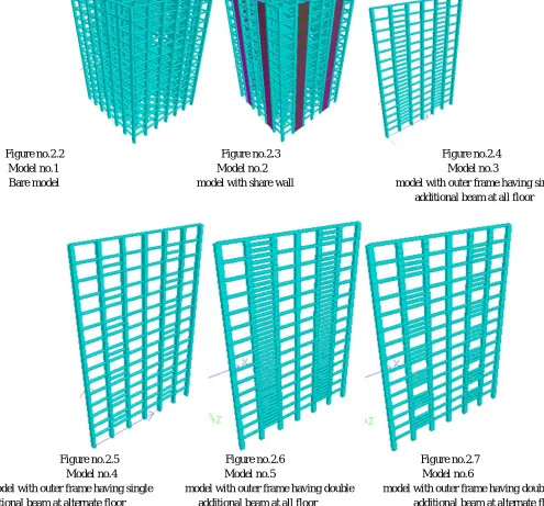
Figure no.2.2 Figure no.2.3 Figure no.2.4 Model no.1 Model no.2 Model no.3
[image:2.612.61.556.127.588.2]Bare model model with share wall model with outer frame having single additional beam at all floor
Figure no.2.5 Figure no.2.6 Figure no.2.7
Model no.4 Model no.5 Model no.6
model with outer frame having single model with outer frame having double model with outer frame having double additional beam at alternate floor additional beam at all floor additional beam at alternate floor
A. Model Properties
1) Model 1:- Model without additional properties (bare frame).
2) Model 2:-Model with shear wall at Second corner column at outer face.
3) Model 3:-Model with single additional beam at place of shear wall at all floor.
4) Model 4:- Model with single additional beam at place of shear wall at alternate floor.
5) Model 5:- Model with double additional beam at place of shear wall at all floor.
6) Model 6:- Model with double additional beam at place of shear wall at alternate floor.
B. Codal Provision
2) IS 1893:2016 (Part-I): Criteria for Earthquake Resistant Design of Structure, General Provision and Building:
3) IS 875-part 1 and 2-for dead load and live considerations. Descriptions of loading
a) Creating seismic definition in definition.
b) In load case assigning earthquake load in X and Z direction
c) Adding Self-weight
d) Adding Dead load of floor and member (wall)
e) Adding Live load on structure
III. RESULTS AND DISCUSSION
Seismic analysis is carried out for all six model by keeping all parameter same and just changing the additional properties i.e. adding additional beams by replacing shear wall for model no. 3 to 6. Various comparative results are as follows.
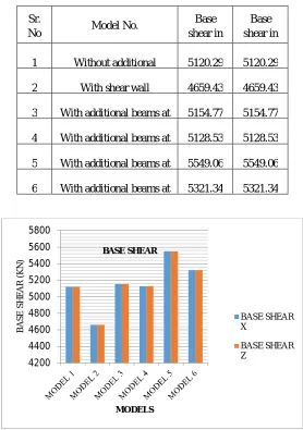
Table no. 3.1-Comparison between base shear
[image:3.612.166.444.268.663.2]
Figure no.3.1-Graph showing base shear
1) Observations From Graph Of Base Shear
a) From graph it is observed that the axial force is minimum for column C1, C2 and C3 for model number 2.
b) In case of model number 4 with beam at position of shear wall at alternate floor is better result compare to other model.
c) Maximum axial force is coming in model number 5 with double beam at position of shear wall compare to other model.
4200 4400 4600 4800 5000 5200 5400 5600 5800
BA
S
E
S
H
E
A
R
(K
N
)
MODELS BASE SHEAR
BASE SHEAR X
BASE SHEAR Z
Sr.
No Model No.
Base shear in X (KN)
Base shear in Z (KN) 1 Without additional 5120.29 5120.29
2 With shear wall 4659.43 4659.43
3 With additional beams at 5154.77 5154.77
4 With additional beams at 5128.53 5128.53
5 With additional beams at 5549.06 5549.06
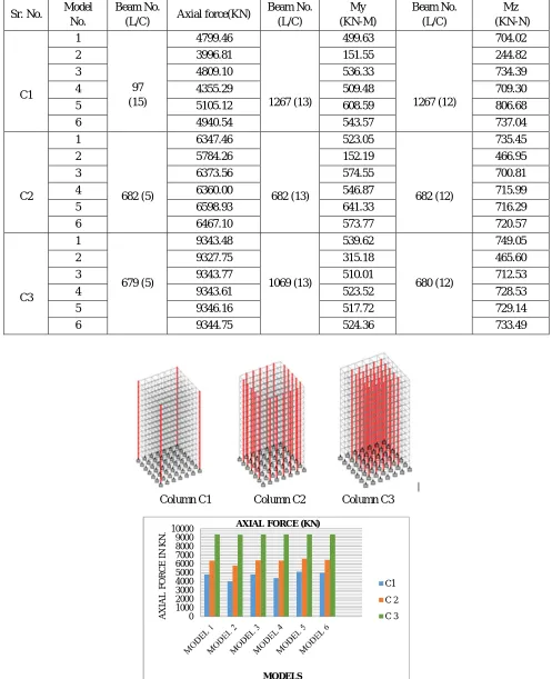
Table no. 3.2-Comparative values for axial force, moment in Y-direction and moment in Z-direction
Column C1 Column C2 Column C3
Figure no. 3.2-Column C1, C2 and C3 are considered as above for better Figure no. 3.3-Comparative axial force for C1, C2 & C3 Comparison
0 1000 2000 3000 4000 5000 6000 7000 8000 9000 10000
A
X
IA
L
F
O
RCE
IN
K
N
.
MODELS AXIAL FORCE (KN)
C1 C 2 C 3 Sr. No. Model
No.
Beam No.
(L/C) Axial force(KN)
Beam No. (L/C)
My (KN-M)
Beam No. (L/C)
Mz (KN-N)
C1
1
97 (15)
4799.46
1267 (13)
499.63
1267 (12)
704.02
2 3996.81 151.55 244.82
3 4809.10 536.33 734.39
4 4355.29 509.48 709.30
5 5105.12 608.59 806.68
6 4940.54 543.57 737.04
C2
1
682 (5)
6347.46
682 (13)
523.05
682 (12)
735.45
2 5784.26 152.19 466.95
3 6373.56 574.55 700.81
4 6360.00 546.87 715.99
5 6598.93 641.33 716.29
6 6467.10 573.77 720.57
C3
1
679 (5)
9343.48
1069 (13)
539.62
680 (12)
749.05
2 9327.75 315.18 465.60
3 9343.77 510.01 712.53
4 9343.61 523.52 728.53
5 9346.16 517.72 729.14
Figure no. 3.4-Comparative moment in Y direction for columns C1, C2 and C3.
Figure no. 3.5-Comparative moment in Z direction for columns C1, C2and C3
2) Observations From Graph Of Moment In Y-Direction
a) From graph it is basically observed that moment in Y-direction is coming very less for model number 2 with shear wall.
b) For C1, value of My is minimum for model no.1
c) For C3, values of My is Minimum in case of model number 4 with beam at position of shear wall at alternate floor other than model number 2.
3) Observations From Graph Of Moment In Z-Direction
a) From graph it is basically observed that moment in Z-direction is coming very less for model number 2 with shear wall.
b) For C1, value of Mz is minimum for model no.1
c) For C3, values of Mz are Minimum in case of model number 4 with beam at position of shear wall at alternate floor other than model number 2.
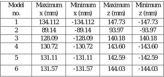
Table no. 3.3-Comparative nodal displacement. 0
100 200 300 400 500 600 700
M
O
M
E
N
T
M
Y
K
N
-M
MODELS MOMENT MY(KN-M)
C 1 C 2 C 3
0 100 200 300 400 500 600 700 800 900
M
O
M
EN
T
M
Z
(K
N
-M
)
MODELS
MOMENT MZ (KN-M)
C 1 C 2
C 3
Model no.
Maximum x (mm)
Minimum x (mm)
Maximum z (mm)
Minimum z (mm) 1 134.112 -134.112 147.73 -147.73 2 89.14 -89.14 93.97 -93.97 3 128.09 -128.09 140.18 140.18 4 130.72 -130.72 143.60 -143.60
5 131.11 -131.11 142.59 -142.59
Figure no. 3.6-Comparative nodal displacement.
4) Observations From Graph Of Nodal Displacement
a) From graph it is clearly seen that minimum nodal displacement occurring it model number 2 with shear wall
b) Graph also indicates that nodal displacement for model no. 3 is less compared to other model
[image:6.612.177.436.323.658.2]c) There is no much different in nodal displacement
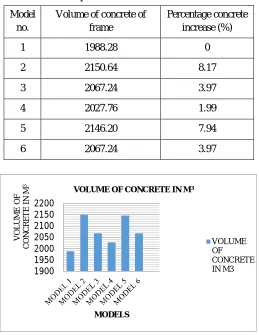
Table no. 3.4-Comparative % increase in volume of concrete.
Figure no. 3.7-Comparative % increase in volume of concrete
5) Observations From Graph Of Volume Of Concrete
a) Model 1 is considered to identify the percentage increase in volume of concrete.
b) Model 2 has maximum volume of concrete requirement
c) Model 4 has minimum (1.99 %) increase of volume of concrete compared to other model. 0 20 40 60 80 100 120 140 160
1 2 3 4 5 6
M A X IM U M N O D A L D IS P L A CE M E N T IN M M MODELS NODAL DISPLACEMENT displacement in X (mm) displacement in Z (mm)
1900 1950 2000 2050 2100 2150 2200 V O L U M E O F CO N CRE T E IN M 3 MODELS
VOLUME OF CONCRETE IN M3
VOLUME OF CONCRETE IN M3 Model no.
Volume of concrete of frame
Percentage concrete increase (%)
1 1988.28 0
2 2150.64 8.17
3 2067.24 3.97
4 2027.76 1.99
5 2146.20 7.94
IV. CONCLUSIONS
On the basis of study of models of structure, the following conclusions can be made.
A. As per axial force criteria, minimum axial force generated at particular fixed column is having minimum value for model number 4.
B. Similarly for moment in y direction and moment in z direction, model number 4 gives good results compared to other model.
C. For displacement criteria there is no much change in displacement for all models but model number 4 has lesser value of nodal displacement amongst all models.
D. For volume of concrete required criteria, model number 2 required more concrete amongst all model, while model number 4 has minimum additional concrete requirement than other model.
E. Model number 4 which has beam alternate floor at place of shear wall gives better results in all amongst all generated model.
F. Shear wall provided in structure provide more stability to structure.
REFERENCES
[1] Kiran Tidke, Rahul Patil, Dr. G.R.Gandhe, “Seismic Analysis of Building with and Without Shear Wall”,International Journal of Innovative Research in Science, Engineering and Technology,Vol. 5, Issue 10, October 2016.
[2] Gaikwad Ujwala Vithal, “Effect of Shear Wall on Seismic Behavior of Unsymmetrical Reinforced Concrete Structure.” International Journal of Research and Scientific Innovation, Volume IV, Issue X, October 2017.
[3] Rakshith K L, Smitha, “Effect of Bracings on Multistoried RCC Frame Structure under Dynamic Loading”, International Journal of Advance Research, Ideas and Innovations in Technology, Volume3, Issue4, 2017.
[4] Sagar R Padol, Rajashekhar S. Talikoti, “Review paper on seismic responses of multistoried RCC building with mass irregularity.” International Journal of Research in Engineering and Technology, Volume: 04 Issue: 03, Mar-2015.
[5] Adithya. M., “Study on Effective Bracing Systems for High Rise Steel Structures.” SSRG International Journal of Civil Engineering, volume 2 Issue 2 February 2015.