3065
©IJRASET: All Rights are Reserved
DC Microgrid for Wind and Solar Electric System
Power Integration
Pooja R. Waghmare
1, Nikita M. Malwar
21, 2Department of Electrical Engineering, Tulsiramji Gaikwad Patil College of Engineering Nagpur
Abstract: Sustainable power sources (SES) are in effect progressively associated in conveyance framework using power electronic converters.
This paper introduces a novel control methodology for accomplishing greatest advantages from this lattice - interfacing inverters when introduced in 3-stage 4-wire conveyance frameworks. The inverter is controlled to execute as multi-work gadget by fusing dynamic power channel usefulness.
The inverter would thus be able to be used as:1)power converter to infuse control created from RES to the matrix, and 2)shunt APF to remunerate current unbalance, load current sounds, load responsive power request and burden impartial current. These capacities might be cultivated either independently or all the while. With such a control, the mix of framework interfacing inverter and the 3-stage 4wire straight/non – direct unequal burden at the purpose of basic coupling shows up as adjusted straight burden to the lattice.
Keywords: Active power filter (APF), distributed generation (DG), distribution system, grid interconnection, power quality (PQ), renewable energy
I. INTRODUCTION
Electric utilities and end clients of electric power are ending up progressively worried about gathering the developing vitality request. Seventy five percent of all out worldwide vitality request is provided by the consuming of petroleum products. Be that as it may, expanding air contamination, an unnatural weather change concerns, reducing petroleum derivatives and their expanding cost have made it important to look towards sustainable sources as a future vitality arrangement. Since the previous decade, there has been a huge enthusiasm for some nations on sustainable power source for power age.
The market advancement and government's motivators have further quickened the sustainable power source division development. Conveyed age (DG) frameworks are displayed as an appropriate structure to offer high dependable electrical power supply [1]. The idea is especially fascinating when various types of vitality assets are accessible, for example, photovoltaic boards, energy components, or speed wind turbines [2], [3].
Most piece of these assets need control electronic interfaces to make up nearby air conditioning matrices [4], [5]. Thusly, inverters or air conditioning to-air conditioning converters are associated with an air conditioner regular transport with the plan to share appropriately the scatter loads associated with the nearby network [6].
The non-straight burden current sounds may result in voltage music and can make a genuine PQ issue in the power framework organize. Dynamic power channels (APF) are broadly used to remunerate the heap current music and burden unbalance at conveyance level. This outcomes in an extra equipment cost.
In any case, in this paper creators have consolidated the highlights of APF in the, customary inverter interfacing inexhaustible with the framework, with no extra equipment cost. Here, the primary thought is the greatest usage of inverter rating which is more often than not underutilized because of irregular nature of RES.
It is appeared in this paper the network interfacing inverter can viably be used to perform following vital capacities: 1) exchange of dynamic power gathered from the inexhaustible assets (wind, sun powered, and so on.); 2) load responsive power request support; 3) current sounds pay at PCC; and 4) current unbalance and unbiased current remuneration if there should arise an occurrence of 3-stage 4-wire framework. In addition, with satisfactory control of network interfacing inverter, all the four goals can be cultivated either separately or at the same time. The PQ imperatives at the PCC can along these lines be carefully kept up inside the utility benchmarks without extra equipment cost.
3066
©IJRASET: All Rights are Reserved
II. SYSTEMDESCRPTION
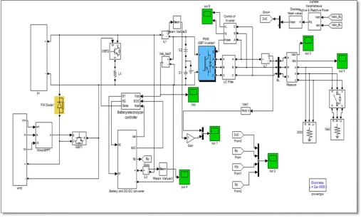
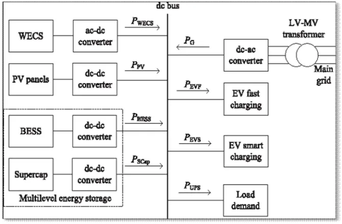
[image:2.595.178.419.152.339.2]The proposed framework comprises of RES associated with the DC-connection of a matrix interfacing inverter as appeared in Fig. 1.and the Simulink structure of conveyance framework is appeared in Fig. 2. The voltage source inverter is a key component of a
Fig. 1. DC Microgrid
DG framework as it interfaces the sustainable power source to the network and conveys the produced power. The RES might be a DC source or an AC source with rectifier coupled to dc-connect. For the most part, the power module and photovoltaic vitality sources produce control at variable low dc voltage, while the variable speed wind turbines create control at variable air conditioning voltage. In this manner, the power created from these sustainable sources needs control moulding (i.e., dc/dc or air conditioning/dc) before associating on dc-connect [6]–[8]. The dc-capacitor decouples the RES from lattice and furthermore permits free control of converters on either side of dc-interface. Simulink structure of wind vitality is appeared in Fig.3.
[image:2.595.44.551.427.733.2]3067
[image:3.595.140.475.111.331.2]©IJRASET: All Rights are Reserved
Fig. 3. Simulink Design of Wind Energy system
III.PROPOSEDCONTROLSTRATEGIES
A. DC- Link voltage and Power Control Operation Due to the intermittent nature of RES, the generated power is of variable nature. The dc-link plays an important role in transferring this variable power from renewable energy source to the grid. RES are represented as current sources connected to the dc-link of a grid-interfacing inverter. Fig. 4 shows the systematic representation of power transfer from the renewable energy resources to the grid via the dc-link. The current injected by renewable into dc-link at voltage level Vdc can be given as
Idc1= Pres/ Vdc (1)
Where, Pres is the power generated from RES. The current flow on the other side of dc-link can be represented as,
Idc2 = Pinv / Vdc = PG+PLoss/Vdc (2)
where Pinv, PG and PLoss are total power available at grid- interfacing inverter side, active power supplied to the grid and inverter losses, respectively. If inverter losses are negligible then
[image:3.595.181.415.557.673.2]Pres = PG
Fig. 4. DC- Link equivalent diagram.
Fig.6. Simulink Design of Grid Interfacing Inverter Control
The regulation of dc-link voltage carries the information regarding the exchange of active power in between renewable source and grid. Thus the output of dc-link voltage regulator results in an active current (Im). The multiplication of active current component
3068
©IJRASET: All Rights are Reserved
dc
dc(n) dc(n)
A. Control of Grid Interfacing Inverter
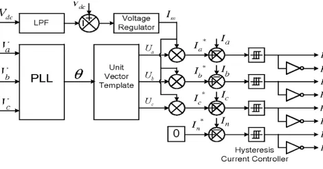
[image:4.595.180.415.213.336.2]The control diagram of grid- interfacing inverter for a 3-phase 4- wire system is shown in Fig. 5. The fourth leg of inverter is used to compensate the neutral current of load. The main aim of proposed approach is to regulate the power at PCC during: 1) Pres=0; 2) Pres < total load power (PL); 3) Pres > total load power. While performing the power management operation, the inverter is actively controlled in such a way that it always draws/ supplies fundamental active power from/ to the grid. If the load connected to the PCC is non-linear or unbalanced or the combination of both, the given control approach also compensates the harmonics, unbalance, and neutral current.
Fig. 5. Block diagram representation of grid-interfacing
zero, being the instantaneous sum of balanced grid currents. The grid synchronizing angle (θ) obtained from phase locked loop
(PLL) is used to generate unity vector template as [9]–[11]
Ua= Sin(θ) (3)
Ub= Sin(θ-2П/3) (4)
Uc= Sin (θ+2П/3). (5)
The actual dc-link voltage is sensed and passed through a first- order low pass filter (LPF) to eliminate the presence of switching ripples on the dc-link voltage and in the generated reference current signals. The difference of this filtered dc-link voltage and reference dc-link voltage (V *) is given to a discrete-PI regulator to maintain a constant dc-link voltage under varying generation and load conditions. The dc-link voltage error Vdcerr(n) at nth sampling instant is given as:
Vdcerr (n) = V * - V . (6)
The output of discrete-PI regulator at nth sampling instant is expressed as
Im(n) = Im(n-1) + KPVdc (Vdcerr (n) - Vdcerr (n-1)) + KIVdc Vdcerr(n) (7)
Where, KPVdc = 10 and KIVdc= 0.05 are proportional and integral gains of dc-voltage regulator. The simulink design of grid interfacing inverter using PI controller is shown in Fig. 6. The instantaneous values of reference three phase grid currents are computed as
Ia*= Im.Ua (8)
The reference grid currents (Ia*, Ib*, Ic*, and In*) are compared with actual grid currents (Ia, Ib, Ic and In) to compute the current errors as
3069
©IJRASET: All Rights are Reserved
[image:5.595.179.421.115.299.2]IV.SIMULATION RESULT
Fig. 6: Voltage generated in DC
[image:5.595.182.420.344.513.2]The DC voltage generated by wind system and solar system is shown in above fig.6. Voltage is generated near about highest peak and then it becomes saturated.
Fig. 7: Voltage generated in AC
The AC voltage generated by wind system and solar system is shown in above fig.7. Voltage is generated in three phase, firstly it having irregular voltage generation then it becomes in sinusoidal form.
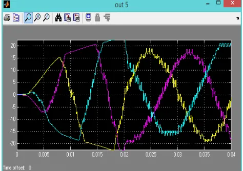
[image:5.595.183.420.562.729.2]3070
©IJRASET: All Rights are Reserved
a
b b
n
The alternating current generated by wind system and solar system is shown in above fig.8. Current is generated in three phase, firstly it having irregular current generation then it becomes in regular i.e. sinusoidal form.
In order to verify the proposed control approach to achieve multi-objectives for grid interfaced DG systems connected to a 3-phase 4-wire network, an extensive simulation study is carried out using MATLAB/ SIMULINK. A 4-leg current controlled voltage source inverter is actively controlled to achieve balanced sinusoidal grid currents at unity power factor (UPF) despite of highly unbalanced nonlinear load at PCC under varying renewable generating conditions. A RES with variable
Iaerr = I *- Ia Iberr = I *- I
Icerr = Ic*- Ic
Inerr = Ia *- In.
These current errors are given to hysteresis current controller. The hysteresis controller then generates the switching pulses (P1 to P8) for the gate drives of grid-interfacing inverter. The average model of 4-leg inverter can be obtained by the following state space equations
dIInva/dt = (VInva –Va) / Lsh (9)
dIInvb/dt = (VInvb –Vb) / Lsh (10)
dIInvc/dt = (VInvc –Vc) / Lsh (11)
dIInvn/dt = (VInvn –Vn) / Lsh (12)
dVdc/dt = (IInvad+IInvbd+IInvcd+IInvnd)/Cdc (13)
Where VInva, VInvb, VInvc, and VInvn are the three-phase ac switching voltages generated on the output terminal of inverter. These inverter output voltages can be modeled in terms of instantaneous dc bus voltage and switching pulses of the inverter as
VInva= (P1-P4)Vdc/2 (14)
VInvb= (P3-P6)Vdc/2 (15)
VInvc= (P5-P2)Vdc/2 (16)
VInvn= (P7-P8)Vdc/2 (17)
Initially, the grid-interfacing inverter is not connected to the network (i.e., the load power demand is totally supplied by the grid alone). Therefore, before time t=0.72s, the grid current profile in Fig. 7 is identical to the load current profile of Fig. 7. At t=0.72s, the grid-interfacing inverter is connected to the network. At this instant the inverter starts injecting the current in such a way that the profile of grid current starts changing from unbalanced nonlinear to balanced sinusoidal current as shown in Fig. 7 shows the simulation results for load and inverter. It can be noticed that as the inverter also supplies the load neutral current demand, the grid neutral current (In) becomes zero after t=0.72 s. The load neutral current due to single phase loads is effectively compensated by the fourth leg of the inverter such that the current in the grid side neutral conductor is reduced to zero.
At t=0.72 s, the inverter starts injecting active power generated from RES (Pres=Pinv). Since the generated power is more than the load power demand the additional power is fed back to the grid. The negative sign of Pgrid, after time 0.72 s suggests that the grid is now receiving power from RES. Moreover, the grid- interfacing inverter also supplies the load reactive power demand locally. Thus, once the inverter is in operation the grid only supplies/receives fundamental active power which is shown in Fig. 9.
3071
©IJRASET: All Rights are Reserved
V. CONCLUSION
This paper has presented a novel control of an existing grid interfacing inverter to improve the quality of power at PCC for a 3-phase 4-wireDGsystem. It has been shown that the grid- interfacing inverter can be effectively utilized for power conditioning without affecting its normal operation of real power transfer. The grid-interfacing inverter with the proposed approach can be utilized to:
A. inject real power generated from RES to the grid, and/or,
B. Operate as a shunt Active Power Filter (APF).
This approach thus eliminates the need for additional power conditioning equipment to improve the quality of power at PCC. Extensive MATLAB/Simulink simulation approach and have shown that the grid-interfacing inverter can be utilized as a multi-function device.
It is further demonstrated that the PQ enhancement can be achieved under three different scenarios: 1)Pres=0 , 2)Pres< PLoad, and 3) Pres > PLoad. The current unbalance, current harmonics and load reactive power, due to unbalanced and non-linear load connected to the PCC, are compensated effectively such that the grid side currents are always maintained as balanced and sinusoidal at unity power factor. Moreover, the load neutral current is prevented from flowing into the grid side by compensating it locally from the fourth leg of inverter. When the power generated from RES is more than the total load power demand, the grid-interfacing inverter with the proposed control approach not only fulfills the total load active and reactive power demand (with harmonic compensation) but also delivers the excess generated sinusoidal active power to the grid at unity power factor.
REFERNCES
[1] Kai Strunz, Ehsan Abbasi, and Duc Nguyen Huu, “DC Microgrid for Wind and Solar Power Integration”, IEEE Journal of emerging and selected topics in Power Electronics, vol. 2, no. 1, March 2014.
[2] Ujwala S. Raut, Y. D. Shahakar, “Optimization of Microgrid for Renewable Power Integration” International Advanced Research Journal in Science, Engineering and Technology, vol. 4, Issue 2, Feb 2017.
[3] Durga Vijayalakshmi, M. D. Aijaz, “Dc Microgrid for Wind & Solar Power Integration” International Journal Of Engineering In Advanced Research Science And Technology, vol -2, Issue-4, Dec.2016
[4] H. Polinder, J. A. Ferreira, B. B. Jensen, A. B. Abrahamsen, K. Atallah, and R. A. McMahon, “Trends in wind turbine generator systems,” IEEE J. Emerg. Sel. Topics Power Electron, vol. 1, no. 3, pp. 174–185, Sep. 2013.
[5] F. Giraud and Z. M. Salameh, “Steady-state performance of a grid connected rooftop hybrid wind photovoltaic power system with battery storage,” IEEE Trans. Energy Convers., vol. 16, no. 1, pp. 1–7, Mar. 2001.
[6] B. S. Borowy and Z. M. Salameh, “Methodology for optimally sizing the combination of a battery bank and PV array in a wind/PV hybrid system,” IEEE Trans. Energy Convers., vol. 11, no. 2, pp. 367–375, Mar. 1996.
[7] M. Cheng, S. Kato, H. Sumitani, and R. Shimada, “Flywheel-based AC cache power for stand-alone power systems,” IEEJ Trans. Electr. Electron. Eng., vol. 8, no. 3, pp. 290–296, May 2013.
[8] H. Louie and K. Strunz, “Superconducting magnetic energy storage (SMES) for energy cache control in modular distributed hydro genelectric energy systems,” IEEE Trans. Appl. Supercond., vol. 17, no. 2, pp. 2361–2364, Jun. 2007.
[9] A. L. Dimeas and N. D. Hatziargyriou, “Operation of a multiagent system for Microgrid control,” IEEE Trans. Power Syst., vol. 20, no. 3, pp. 1447–1455, Aug. 2005.
[10] F. Katiraei and M. R. Iravani, “Power management strategies for a microgrid with multiple distributed generation units,” IEEE Trans. Power Syst., vol. 21, no. 4, pp. 1821–1831, Nov. 2006.
[11] A. G. Madureira and J. A. Pecas Lopes, “Coordinated voltage support in distribution networks with distributed generation and microgrids,” IET Renew. Power Generation, vol. 3, no. 4, pp. 439–454, Dec. 2009.
[12] M. H. Nehrir, C. Wang, K. Strunz, H. Aki, R. Ramakumar, J. Bing,et al., “A review of hybrid renewable/alternative energy systems for electric power generation: Configurations, control, and applications,” IEEE Trans. Sustain. Energy, vol. 2, no. 4, pp. 392–403, Oct. 2011.
[13] R. Majumder, B. Chaudhuri, A. Ghosh, R. Majumder, G. Ledwich, and F. Zare, “Improvement of stability and load sharing in an autonomous microgrid using supplementary droop control loop,” IEEE Trans. Power Syst., vol. 25, no. 2, pp. 796–808, May 2010.
[14] D. Westermann, S. Nicolai, and P. Bretschneider, “Energy management for distribution networks with storage systems—A hierarchical approach,” in Proc. IEEE PES General Meeting, Convers. Del. Electr. Energy 21st Century, Pittsburgh, PA, USA, Jul. 2008.
[15] A. Chaouachi, R. M. Kamel, R. Andoulsi, and K. Nagasaka, “Multiobjective intelligent energy management for a microgrid,” IEEE Trans.Ind. Electron, vol. 60, no. 4, pp. 1688–1699, Apr. 2013.
[16] R. Palma-Behnke, C. Benavides, F. Lanas, B. Severino, L. Reyes, J. Llanos, et al., “A microgrid energy management system based on the rolling horizon strategy,” IEEE Trans. Smart Grid, vol. 4, no. 2,pp. 996–1006, Jun. 2013.