Performance Analysis of 5G Network Based on
BDMA and Massive - MIMO
Shweta Vij1, Naazia Makkar2
1, 2
Department of Electronics and Communication Engineering, Guru Nanak Dev Engineering College, Ludhiana, Punjab
Abstract: Beyond 4G, 5G is the next generation proposed telecommunications standard that will support large number of users with the introduction of Massive MIMO and beam-forming. Main area of focus of 5G network is capacity enhancement with the deployment of large number of antennas (Massive MIMO) whereas LTE focuses on high speed rather than capacity. LTE-A is the advanced version of LTE with the advancement in its features as well. LTE-A supports bandwidth of 100 MHz to 6GHz, therefore below 6GHz, 5G network will operate on LTE-A network and above 6 GHz range, 5G will offer large bandwidth with small coverage area due to path loss at high frequencies. This work presents capacity analysis with the help of BDMA and Massive MIMO techniques where outage probability considered is 10% and reduction of interference using beam forming. Keywords: MU-MIMO; BDMA; 4G; 5G, LTE-A.
I. INTRODUCTION
Wireless technology has improved, overcoming the shortcomings of previous generations leading to advent of new technology with enhanced performance. As the world becomes more automated than what it was, a continuous need of higher data transfer rate becomes the need of the hour. A faster network seems more inevitable than ever as more and more devices come online with every passing day. With the current data transfer rates our data network speed may not be able to sustain the continuous influx of device over the internet for very long. Hence the need for the upgraded technology, i.e. 5G, that will cater for increased capacity and reduced interference. 5G deployments also aims at achieving lower latency than what LTE network has achieved and efficient consumption of battery, for implementing internet of things [4]. Currently there is no standard that has been defined for 5G deployments. LTE manages swift hand-offs for fast-moving users and supports broadcast streams [10]. LTE supports both time-division duplexing (TDD) and frequency time-division duplexing (FDD) bandwidths from 1.4MHz to 20MHz.
II. BDMA
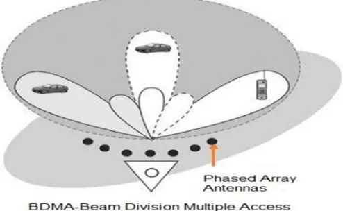
[image:1.612.185.432.561.713.2]Various multiple access techniques that are in use for the optimum use of common resources by multiple users such as time, frequency, codes etc. has led to the development of FDMA, TDMA, CDMA and OFDM techniques. The main aim here is to provide quality service to the users at affordable price. Multiple users share the most critical resources such as time and frequency using TDMA and FDMA access techniques respectively. The Korean researchers have devised new access technique known as BDMA for the fifth generation of mobile wireless communication systems [2]. BDMA stands for Beam Division Multiple Access. This technique does not utilize time and frequency resource sharing rather it forms beam that covers multiple users in the neighboring area [16].
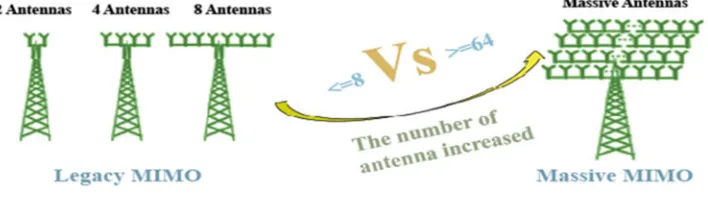
This antenna technology has gained popularity in wireless communications and has since then been incorporated into many wireless standards like LTE and Wi-Fi. The concept behind deploying large number of antennas at transmitter and receiver end is to increase the possible paths for signal and thereby improving the performance in terms of data rate and reliability of the link [15]. There is a trade-off between performance and price that has to be paid due to high level of complexity of the hardware used and the energy consumption involved in signal processing at both the ends.
Fig 1.2 Massive MIMO
Massive MIMO that is also known as Very Large MIMO, Large-Scale Antenna Systems and Hyper MIMO brings a change in the current day practice by introducing very large number of antennas at both transmitter and receiver ends that operate in coherent and adaptive manner [3]. These antennas help to cover smaller areas by the method of focusing the transmission and reception signal energy coming from various devices. This leads to significant improvement in throughput and also leads to energy efficiency in case of large number of users [3].
It has other benefits that include the use of low cost and low-power components, reduced weight of antennas and reduced latency, and immune to interference and frequency jamming. The proposed throughput also depends on the propagation media where channels are orthogonal to the terminals [17]. While massive MIMO overcomes traditional problems, it exposes entirely new problems which needs urgent attention; such as, to face the challenge of making multiple low-cost and low-precision components which work together effectively, the need for efficient resource allocation for the newly formed terminals, reducing total internal power consumption thus providing energy efficiency reductions, and finding new areas for deployment.
IV. BEAMFORMING
Fig 1.3 Beamforming at various angles
Beamforming has found its application in various utilities viz. radar, sonar, seismology, wireless communications, acoustics and biomedicine. Adaptive beamforming is being used for detecting and estimating the signal-of-interest at the output of antenna by means of optimal spatial filtering and also by interference rejection [15].
The beamforming algorithms in massive MIMO systems are executed at the digital baseband and get very complex. In addition, if beamforming operation is done at the baseband, each antenna will require its own RF feed. With large number of antenna elements at high frequencies, this will be very costly, increased path loss and complexity in the system [8]. Solution to these problems is addressed by hybrid beamforming which is a combination of both analog and digital components.
Beamforming requires antennas that have multiple inputs and multiple outputs thereby using a variety of techniques for signal processing for broadcasting different signals at different antennas via different signal paths, ensuring that these signals interfere in such a way that a stronger signal is broadcasted in a specific direction [15]. Beamforming technique is a type of radio frequency management in which one access point uses multiple antennas to transmit the same signal.
The table below describes the evolution of wireless generations, difference in the technologies used, data rates and bandwidth.
Table 1.1 Comparison of wireless generations [6]
Generation Data rate Technology Time period Applications Bandwidth
3G 5-30 Mbps
Wideband Code Division Multiple Access (WCDMA) and Universal
Mobile Telecommunication
Systems (UMTS)
2009-2015
Online gaming, video calling and high definition
TV
5 MHz
4G 100-200Mbps
Long term evolution, Orthogonal Frequency Division Multiple Access
(OFDMA), SC-FDMA
2007-2016 Online gaming + high
definition applications 1.8 GHz to 20 GHz
5G 10-50Gbps
Long term evolution-Advanced(LTE-A), Beam
Division Multiple Access (BDMA) and Filter Bank
Multicarrier (FBMC)access
Deployment expected by
2020
Ultra high definition video + Virtual reality
[image:3.612.67.548.437.717.2]assuming that the signal power is bounded, and also that the Gaussian noise process is given by a known power or power spectral density. It is formulated by:
C = B.log2(1+SNR)
Where, C is Channel capacity in bits per second. B is Bandwidth in Hertz.
and SNR is Signal to noise ratio in dB.
The above relation shows that Capacity is directly proportional to SNR, i.e. as the capacity of the system is improved so does the
SNR value. Outage probability is an apparent measure of performance which is defined as the probability when mutual information
[image:4.612.199.451.357.512.2]is less than the given threshold. The importance of outage probability is that when outage occurs, there is a higher probability of having a decoding failure. It is basically a typical error.
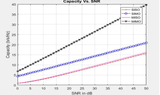
Fig 7.1 Graph of Capacity vs SNR for LTE-A (nT=2, mR=2)
The graph plotted above between capacity and SNR is for LTE-A network where MIMO technology is used by deploying 2 antennas each at transmitter and receiver end.
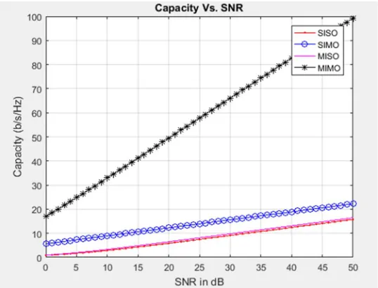
[image:4.612.188.452.564.721.2]Fig 7.3 Graph of Capacity vs SNR for 5G (nT=2, mR=50)
Fig 7.4 Graph of Capacity vs SNR for 5G (nT=5, mR=50)
[image:5.612.176.462.534.713.2]Fig 7.6 Graph of Capacity vs SNR for 5G (nT=20, mR=50)
[image:6.612.75.539.350.462.2]The above graphs are plotted for different combinations of transmitting and receiving antennas in 5G network that uses Massive MIMO technology, where number of antennas is increased. Variation in number of antennas shows that as the number of antennas is increased, capacity of the system increases drastically.
Table 7.1 Capacity in 5G networks for different number of antennas Number of transmit
antenna, nT
Number of receive antenna ,mR
Capacity (b/s/Hz)
2 2 2
2 20 7
2 50 10
5 15 18
50 100 70
20 50 35
B. Simulation of LTE-A and 5G network using Massive MIMO and beamforming for interference
Interference is one of the major concerns in wireless communication which can be caused by signal transmission from the adjacent cells within the same cluster or by the cells in neighboring cluster.
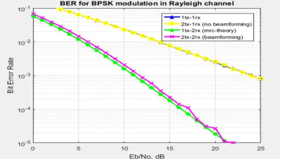
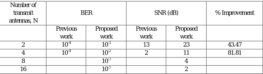
To mitigate the effect of interference, beamforming technique is used in 5G network. The effect of introducing beamforming can be studied from the graphs of BER and SNR, where, beamforming improves the performance of system by reducing the BER to a great extent as compared to no beamforming.
[image:6.612.189.463.566.721.2]Fig 7.7 Graph of BER vs SNR with beamforming (N=4)
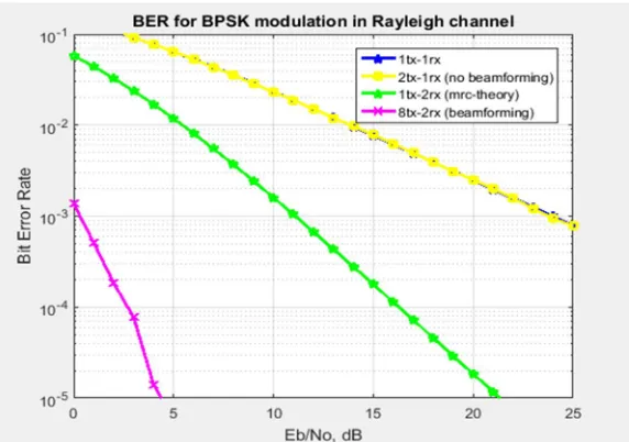
Fig 7.8 Graph of BER vs SNR with beamforming (N=8)
[image:7.612.184.465.522.719.2]4 10-4 10-2 2 11 81.81
8 10-3 4
16 10-5 2
The above graphs are obtained by varying number of transmitting antennas the effect of varying the number with beamforming is reflected upon BER. As the number of antennas increase, BER reduces. The modulation scheme used is BPSK in Rayleigh fading channel.
VII. CONCLUSION
Capacity analysis of LTE-A and 5G networks is done using MIMO and M-MIMO respectively and the results show improvement in system capacity as we increase the number of transmit and receive antennas. We have analyzed the results starting from 2 transmit and receive (MIMO) antennas to 50 to 100 transmit and receive antennas (M-MIMO) and the capacity has drastically improved from 2b/s/Hz to 70b/s/Hz showing improvement of about 65%.
To mitigate the effect of interference in 5G network, beamforming technique is used. By varying the number of transmit antennas
from N=2 to N=16 using BPSK modulation scheme it is observed that BER has improved from 10-1 to 10-5 showing improvement of
about 60%.
It can be concluded that there is a trade-off between BER and SNR. BER improves at the cost of SNR. Also the speed and capacity that is improved comes at the cost of introducing new device, it cannot be achieved with the current device. As the technology advances, so does the need to upgrade to new device that supports new technology.
VIII. FUTURE SCOPE
The improvement areas that can be addressed in future include following:
A. There is a trade-off between BER and SNR, BER improves as we vary the number of antennas but SNR reduces therefore, SNR
can be improved.
B. Work can be also be extended to mitigate co-channel interference when the number of antennas is increased.
REFERENCES
[1] Akyildiz, I. F., Nie, S., Lin, S. C., Chandrasekaran, M. (2016), “5G roadmap: 10 key enabling technologies,” Journal of Science Direct, vol. 106, pp. 17–48. [2] Beam Division Multiple Access [Online]. Available: http://www.rfwireless-world.com
[3] Benisha, M., Thandaiah, P. R. and Thulasi, B. V. (2016), “Requirements and Challenges of 5G Cellular Systems,” Proceedings of International Conference on Advances in Electrical, Electronics, Information, Communication and Bio-Informatics (AEEICB), Chennai, India, pp. 251-254
[4] Borkar, S. and Pande, H. (2016), “Application of 5G Next Generation Network to Internet of Things,” Proceedings of International Conference on Internet of Things and Applications, Pune, India, pp. 443-447
[5] Chen, L., Zhu, P., Zhang, S., You, X. (2013), “Outage Capacity Analysis of LTE-A Transmission Techniques,” Proceedings of IEEE/CIC International Conference on Communications in China (ICCG), Signal Processing for Communications, Xi'an, China, pp.281-285.
[6] Gupta, A.and Jha, R. (2015), “A survey of 5G network: architecture and emerging technologies,” IEEE Journal of recent Advances in Software Defined Networking for 5G networks, vol. 3, pp. 1206-1232.
[7] Idachaba, F. E. (2016), “5G Networks: Open Network Architecture and Densification Strategies for beyond 1000x Network Capacity Increase,” Proceedings of Future Technologies Conference (FTC), San Francisco, CA, USA, pp. 1265-1269.
[image:8.612.87.526.138.263.2][9] Nichita, M. V., Ciotirnae, P., Luca, R. L. and Petrescu, V. N. (2016), “5G Propagation: Current Solutions and Future Proposals,” IEEE International Symposium on Electronics and Telecommunications (ISETC), Timisoara, Romania, pp. 47-50.
[10] Olwal, T. O., Djouani, K. and Kurien, A. M. (2016), “A Survey of Resource Management Toward 5G Radio Access Networks,” IEEE Communications Surveys and Tutorials, vol. 18, pp. 1656-1686.
[11] Patel, N. (2015), “An overview on 5G technology,” International Journal of Electronics, Communication and Soft Computing Science and Engineering (IJECSCSE), vol. 4, pp. 418-422.
[12] Patil, S., Patil, V. and Bhat, P. (2012), “A review on 5G technology,” International Journal of Engineering Innovative Technologies, vol.1, pp. 26-30.
[13] Raheem, R., Lasebae, A. , Aiash, M. and Loo, J. (2016), “Interference Management for Co-Channel Mobile Femtocells Technology in LTE Networks,” Proceedings of International Conference on Intelligent Environment, London, UK, pp.80-87.
[14] Proceedings of International Conference on Computing Sustainable Global Development, New Delhi, India, pp.2137-2140.
[15] Suban, A., Priyanka, V. S., Atchaya, S. (2013), “Interference Mitigation in LTE- Advanced MU-MIMO through Beamforming Technique,” International Journal of Advanced Research in Computer Engineering & Technology (IJARCET), vol.2, pp.555-558.
[16] Sun, C., Gao, X., Jin, S., Matthaiou, M., Ding, Z. and Xiao, C. (2015), “Beam Division Multiple Access Transmission for Massive MIMO Communications,” IEEE Transaction on Communication, vol. 63, pp.2170-2184.
[17] Sun, Q., Wang, W., Zhong, W. and Gao, X. (2015), “Link adaptation method based on mutual information for BDMA massive MIMO transmission system”, Proceedings of International Conference on Wireless Communication and Signal Processing, Nanjing, China, pp. 1-5.
[18] Thaherbasha, S. and Parveen, S. (2016), ‘‘Erlang capacity estimation of OFDMA-based cellular systems under co-channel interference’’, International Conference on Wireless Communication, Signal Processing and Networking, Chennai, India, pp. 2439-2443.
![Table 1.1 Comparison of wireless generations [6]](https://thumb-us.123doks.com/thumbv2/123dok_us/1254889.652671/3.612.221.418.107.198/table-comparison-of-wireless-generations.webp)