Analysis of Strain Transfer through the Mg/Ti Interface Using Crystallographic
Orientation Analysis Based on Electron Back-Scattered Diffraction Patterns
Hiroaki Kawamoto
*, Seiji Miura, Kaori Yano
*, Kenji Ohkubo and Tetsuo Mohri
Division of Materials Science and Engineering, Graduate School of Engineering, Hokkaido University, Sapporo 060-8628, Japan
Improvement of deformability for Mg-based composite materials with a dispersion of Ti particles has been considered in terms of the strain transfer through the interface, but is not fully understood during the deformation of ductile Ti particles. Mg-based composites composed of pure Mg and pure Ti plates was investigated to clarify the strain transfer through the Mg/Ti interface using crystallographic orientation analysis based on electron back-scattered diffraction (EBSD) patterns. It is suggested that the larger Schmid factor and lower residual strain energy (W) are significant for the operation of a prismatic slip system in the Ti grains. [doi:10.2320/matertrans.MC200764]
(Received October 22, 2007; Accepted December 6, 2007; Published February 27, 2008) Keywords: electron back-scattered diffraction, bending test, twinning
1. Introduction
Recently, considerable attention has been paid to Mg alloys having high specific strength and recyclability, with consideration for the global environment and efficient energy utilization. However, there is a problem in that the processing of Mg at ambient temperature is quite difficult, because Mg has a hexagonal close-packed structure. The axial ratio (c=a) of Mg is smaller than the ideal value; therefore, it is difficult to activate both prismatic and pyramidal slip systems at ambient temperature, although it is easy to activate basal slip systems. Strain incompatibility in the grain boundary during deformation (e.g., rolling and forging) with a small number of slip systems causes intergranular fracture during the early period of deformation at ambient temperature;1) therefore, casting is the conventionally used processing method.
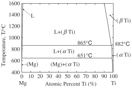
This investigation focuses on Mg alloy composite materi-als with improved deformability and/or toughness. Improve-ment in the toughness of brittle materials such as interme-tallic compounds can be achieved by the dispersion of ductile particles.2)In order to apply such an approach to metal-metal composites, it is necessary to select a suitable dispersoid that deforms plastically with a stress level lower than the maximum strength of the matrix. If such dispersoids are present at Mg grain boundaries, they are expected to alleviate grain boundary stress concentration and prevent cracking. Also, the dispersoid should equilibrate with Mg without a large solid solubility or the formation of brittle intermetallic compounds. Although several researchers have attempted to fabricate Mg-based metal-metal composites,3–7)Ti fulfills the dispersoid requirements, as shown in Fig. 1, and the improvement of deformability for a Mg-based composite material with a dispersion of Ti particles has been report-ed.8,9) In addition, it was reported that for a Mg-based composite material with a non-uniform-distribution of 20 vol% Ti particles, cracks propagate mainly through the Mg matrix where the density of Ti particles is low.10) Considering a previous result that shows good adhesion for the Mg/Ti,10) this implies that the high degree of strain compatibility at the Mg/Ti interface will alleviate cracking
near the Ti particles. However, the strain transfer through the interface during the deformation of ductile Ti particles is not fully understood. Therefore, in the present study, an orientation imaging microscopy (OIM) study was conducted with an electron back-scattered diffraction (EBSD) analysis to clarify the strain transfer through the Mg/Ti interface in a composite composed of pure Mg and Ti.
2. Experimental Procedures
A pure Ti ingot was rolled out to a thickness of 0.6 mm and annealed at 800C for 3 hours in an evacuated silica tube. A
pure Mg ingot of approximately 70 g was placed in a high purity graphite crucible and heated to the melting point of Mg using an induction heater under an Ar atmosphere. The Ti plate was immersed into the molten Mg, and the composite was immediately solidified in the crucible and processed into a suitable shape for the three-point bending test, as illustrated in Fig. 2. The 101:5mm observation side of the test sample was mechanically polished with emery paper (#2000) and colloidal-silica (SiO2). Three-point bending tests were
conducted and a laser scanning confocal microscope (LSCM; type 1LM21H, Lasertech Inc.) was used forin-situ observa-tion of the surface state and the deformaobserva-tion sequence was recorded using a video camera recorder.
Atomic Percent Ti (%) 651°C 865°C 1600
1400
1200
800
600
Temperature, T/
oC
0
Mg Ti
1000
(βTi)
(αTi)
(Mg) L
882°C
L+(βTi)
L+(αTi)
(Mg)+(αTi)
400
10 20 30 40 50 60 70 80 90 100
Fig. 1 The Mg-Ti binary phase diagram.
*Graduate Student, Hokkaido University
[image:1.595.313.542.287.440.2]The EBSD method has been known to provide information on the crystallographic orientation in a larger area, compared with transmission electron microscope (TEM) observation; therefore, characteristic deformation behavior such as the formation of twins and misorientation of the crystal lattice by dislocation motion can be investigated by observing the deformed surface in the vicinity of the Mg/Ti interface. For such purposes, a field-emission scanning electron microscope (FE-SEM; JSM-6500, Jeol) was used with an acceleration voltage of 20 kV, and Kikuchi patterns were recorded with a CCD camera for the EBSD analysis using OIM ver4.5 (TSL Crystallography). Prior to the EBSD analysis, a cross section polisher (SM-09010, Jeol) was employed to polish both Mg and Ti, and Mg was electrochemically polished (electrolyte component; methanol:nitric acid¼20 : 3) to finish the surface in order to obtain high quality EBSD patterns. Cross-section polishing, which is a method for polishing a wide-ranging sample section with argon ions, was applied for
6 hours at an acceleration voltage of 6.0 kV and an ion electric current of 132 A.
3. Results
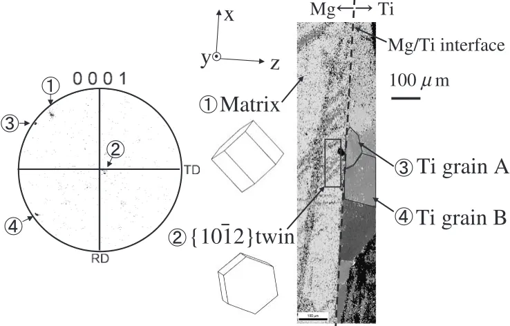
Figure 3 shows the result of LSCM observation of a specimen after the bending test. The appearance of slip-traces and the occurrence of twin-reliefs on the surface of the Mg area near the location of the center pin were confirmed. Figure 4 shows the result of the crystallographic orientation analysis in the vicinity of the Mg/Ti interface, which corresponds to the analysis area indicated in Fig. 3. The dotted line indicates the Mg/Ti interface, and the areas to the left and right of the dotted line are Mg and Ti, respectively. As indicated in Fig. 2, it is noted that the Mg/Ti interface is perpendicular to the observed surface. EBSD analysis revealed that the Mg area of the specimen consists of one large crystal grain, while the Ti area consists of several grains. The orientations of the Mg grain, the dark stripes in the square, Ti grains A and B are indicated in a (0001) pole figure. It was confirmed that the angle between [0001] axis of
0.6mm
2mm
1. 5mm
10mm
Pins
Center pin
Ti
Mg
y
x
z
Fig. 2 Schematic illustration of the three-point bending test set-up.
Ti
Mg
Mg
600
µ
m
Area
analyzed by EBSD
Center pin
Fig. 3 Laser microscope observation after the bending test.
Mg/Ti interface
Ti grain A
Ti grain B
100
µ
m
Mg
Ti
x
y
z
Matrix
{1012}twin
[image:2.595.310.540.73.209.2] [image:2.595.57.281.75.246.2] [image:2.595.113.482.530.766.2]the Mg grain and the dark stripes in the square is about 86,
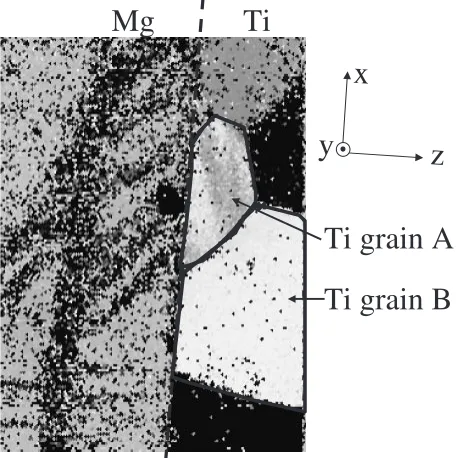
which means the dark stripes are {10112} twin. It was also found that the {10112} twin can be formed by the applied stress during the bending test. A magnified view of the center part of Fig. 4 is shown in Fig. 5 with the contrast improved. A gray-tone gradation can be recognized only in Ti grain A. EBSD analysis revealed that in Ti grain A the gray-tone gradation corresponds to the lattice misorientation of about 5. Such intra-grain misorientations have been used to
understand the introduction of dislocations.11) The {10112} twins in the Mg grain reach the interface with Ti grain A, while no twins are observed near the interface with Ti grain B. No gray-tone gradation is found in the Mg area.
4. Discussion
Although the selection of a slip system is primarily controlled by the Schmid factor, the operation of deformation mechanisms near a grain boundary is also strongly affected by the strain compatibility.11)Therefore, the difference in the twin formation behavior observed in Fig. 5 can be attributed to the strain compatibility at the Mg/Ti interface, as well as the difference in the magnitude of the Schmid factors for the slips in Ti grains A and B.
In the following discussion, all the strain components in both Mg and Ti, which are converted into an interfacial coordinate system shown in Fig. 5, are employed to under-stand the strain compatibility at the interface, the x-y plane. Generally these strain components ("xx, "yy and "xy) are
utilized to understand the effect of the interface on the onset of deformation mechanisms,12)or the selection of the variant of martensite.13)If three strain components ("xx,"yy and"xy),
which are introduced by the deformation of grains near the interface, fulfill the following requirements, then the strain compatibility between Mg and Ti is maintained and no strain energy is introduced at the interface.
"Mxx¼"Txx; "Myy¼"Tyy; "Mxy¼"Txy; ð1Þ
where superscripts M and T represent Mg and Ti, respec-tively.
The strain components can be estimated by taking the plastic deformation behavior analyzed by EBSD into ac-count. In the Mg grain, twinning was confirmed by EBSD, and"M
xx," M yyand"
M
xywere calculated. On the other hand, a very
small lattice misorientation was confirmed by the inverse pole figure of Ti grain A, while no evidence of lattice misorientation was obtained for Ti grain B. The lattice misorientation was too small to decide the slip system in Ti grain A. For both Ti grains A and B in the present study the Schmid factors for basal slips are almost the same with those for prismatic slip systems. However the CRSS for prismatic slip systems is much lower than that of basal slip systems at ambient temperature.14,15) Therefore, in the following dis-cussion, it is assumed that the prismatic slip system is operated in Ti grains. However, it was found that neither prismatic nor basal slip systems in Ti grains fulfill eq. (1) for the present study. Hence, in the present study, in order to evaluate the degree of strain compatibility, the following expression was applied.
W ¼E
2 "
M xx"
T xx
2
þE
2 "
M yy"
T yy
2
þ2G
2 "
M xy"
T xy
2
; ð2Þ
whereW is the ‘‘residual’’ elastic strain energy at the grain boundary, introduced by the difference in the strain compo-nents of the Mg twin and Ti slips.EandGare the Young’s modulus and shear modulus around a grain boundary, respectively. If each of the strain components for Mg and Ti is the same,Wis zero and the interface has no effect on the deformation of both grains.
The engineering shear strain @y
@z for the {10112} twin is 0:1299 for pure Mg (Fig. 6(a)). The shear strain is generally defined as follows.
Ti grain A
Ti grain B
Mg
Ti
x
y
z
Fig. 5 Close-up of the central part of the specimen shown in Fig. 4.
(a) Mg{1012} twin (Coordinate system 1)
'
'
=
1.154
=
∂
∂
A
B
y
x
δ
x
y
z
B’ A’
= −
0.1299
=
∂
∂
A
B
z
y
δ
(b) Ti prismatic slip system (Coordinate system 2)
c = 1.623 a
a
3 2
B
A
y
z
x
Original lattice Twin lattice
c
[image:3.595.298.543.73.261.2] [image:3.595.55.283.76.305.2]"ij¼
1
2 @i
@xj þ@j
@xi
: ð3Þ
Hence, the strain matrix was described in the coordinate system 1 as follows.
M¼
0 0 0
0 0 0:065 0 0:065 0
0 B @
1 C
A: ð4Þ
Similarly, the engineering shear strain@x
@y for the motion of a
perfect dislocation along [11220] with a size of the lattice constant, a, on the {10110} prismatic plane of Ti is 1.154 (Fig. 6(b)). Then, the strain matrix can be defined in the coordinate system 2 as follows.
M ¼
0 0:577 0 0:577 0 0
0 0 0
0 B @
1 C
A: ð5Þ
M can be converted to M0 in the interfacial coordinate
system. The converted strain matrixM0 is given by
M0¼RMRt; ð6Þ
whereRis the coordinate transformation matrix andRtis a
transpose ofR.R is obtained using the pole figure of each grain.
The components ofM0,"M xx,"
M yyand"
M
xy, for Mg {10112} twin
at the Mg/Ti interface are shown in Table 1. On the other hand, no limitation exists in the amount of the shear strain by the prismatic slip operation in Ti grains. Hence, eq. (6) for Ti prismatic slip systems is modified as follows.
M0¼RMRt; ð7Þ
whereis the number of dislocation per glide plane (¼1 for the case in which one dislocation moves on every (10110) plane) andis determined to minimize the ‘‘residual’’ elastic strain energy W. The results, "Txx, "Tyy and"Txy for the three equivalent prismatic slip systems in Ti grains in the
interfacial coordinate system, are also shown in Table 1. The results of the estimation of the ‘‘residual’’ elastic strain energyWfor three prismatic slip systems in the two Ti grains are shown in Table 2 in the order of the Schmid factor. Three equivalent prismatic slip systems are referred to as PSS (prismatic slip system) 1, 2, and 3. It was noted that as the ratios ofEtoGare almost the same for Mg (ratio¼2:66) and Ti (ratio¼2:86), the sum of the actual ‘‘residual’’ elastic strain energies in Mg and Ti at the Mg/Ti interface is expected to be proportional to the estimated value for W
estimated usingEandGof Ti or Mg. In this present study the
E (¼4:43104MPa) and G (¼1:66104MPa) of Mg were employed for the estimation of W (MJ/m3), and the results are shown in Table 2. Without plastic deformation in Ti grains, the value of ‘‘residual’’ elastic strain energy W0
with the twin in Mg is 111 MJ/m3 in the present case, obtained by substituting "T
ij¼0 and applying the strain
components of Mg twin in Table 1 into eq. (2).
Considering the results given in Table 2, the value ofW
has significantly decreased, by the operation of PSS 1 in both Ti grains A and B, from the value ofW0(¼111MJ/m3). This
suggests that the PSS 1 is the preferred operation in both Ti grains A and B. However, the Schmid factor (Sf) of PSS 1 in Ti grain A is larger than that in Ti grain B. For the operation of PSS 1, the stress along x-axis during bending is primarily important. The deformation in Ti grain A is seemingly assisted by this stress, because it has a larger Schmid factor. On the other hand, in Ti grain B, the dislocation motion for PSS 1 is not expected, because of the lower Schmid factor, resulting in the lack of Mg twinning.
For further understanding, it is necessary to identify the slip system by optical and/or SEM observation of the slip trace lines or by TEM observation. Moreover, the calculation should be conducted by taking the influence of other slip systems and the difference of the thermal expansion coefficients of Mg and Ti into account.
5. Conclusion
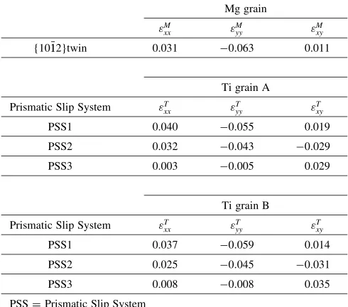
[image:4.595.304.549.94.180.2]In order to clarify the strain transfer through the Mg/Ti interface in a composite made of pure Mg and pure Ti, characteristic deformation behavior such as twin formation and crystal lattice misorientation by dislocation motion were investigated by observing the deformed surface in the vicinity of the Mg/Ti interface. It was found that twinning in the Mg grain is associated with dislocation motion in Ti Table 1 "M
xx,"Myyand"Mxyfor the Mg {10112} twin at the Mg/Ti interface and
"T
xx,"Tyyand"Txyfor the three equivalent prismatic slip in Ti grains in the
interfacial coordinate system.
Mg grain
"M
xx "Myy "Mxy
{10112}twin 0.031 0:063 0.011
Ti grain A Prismatic Slip System "T
xx "Tyy "Txy
PSS1 0.040 0:055 0.019
PSS2 0.032 0:043 0:029
PSS3 0.003 0:005 0.029
Ti grain B Prismatic Slip System "T
xx "
T
yy "
T xy
PSS1 0.037 0:059 0.014
PSS2 0.025 0:045 0:031
PSS3 0.008 0:008 0.035
PSS = Prismatic Slip System
Table 2 ‘‘Residual’’ elastic strain energyW at the Mg/Ti interface and Schmid factors (Sf) of prismatic slip systems in Ti grains A and B.
Ti grain A Ti grain B
W Sf W Sf
PSS 1 4.8 0.34 1.3 0.28
PSS 2 35.5 0.29 39.4 0.20
PSS 3 97.0 0.06 85.1 0.08
Mg twin Reached Not reached
PSS = Prismatic Slip System
W0¼111MJ/m3(with the twin in Mg and without plastic deformation
[image:4.595.46.291.106.322.2]grains. The estimation of ‘‘residual’’ elastic strain energyW
at a grain boundary was conducted for the combination of the Mg twin and Ti prismatic slips, and it was found that the larger Schmid factor and the lowerW are significant for the selection of the operation of the prismatic slip system in a Ti grain.
REFERENCES
1) J. Koike: Metall. Mater. Trans. A36A(2005) 1689–1696.
2) J. J. Kruzic, J. H. Schneibel and R. O. Ritchie: Metall. Mater. Trans. A
36A(2005) 2393–2402.
3) B. A. Wilcox and A. H. Clauer: Trans. Met. Soc. AIME245(1969) 935–939.
4) Y. Tsunekawa, M. Okuyama, I. Niimi and T. Yamada: The Journal of the Casting Institute of Japan60(1988) 596–601.
5) I. Niimi, M. Okuyama, K. Kuramochi and T. Sugimoto: The Journal of the Casting Institute of Japan66(1994) 263–268.
6) J. A. Jensen and L. S. Chumbley: Metall. Mater. Trans. A29A(1998) 863–873.
7) S. F. Hassan and M. Gupta: J. Alloys and Compounds335(2002) L10– L15.
8) M. Hida: Kinzoku, Materials Science & Technology68(1998) 232– 238.
9) S. Miura and T. Mohri: The Fourth Pacific Rim International Conference on Advanced Materials and Processing (PRICM4), Ed. by S. Hanada, Z. Zhong, S. W. Nam and R. N. Wright, (The Japan Institute of Metals, 2001), 1947–1950.
10) K. Yano: Master thesis, Hokkaido University (2006), ‘Deformation behavior of Mg-base composite with ductile Ti’.
11) D. Chandrasekaran and M. Nyga˚rds: Acta Materialia51(2003) 5375– 5384.
12) P. Peralta and C. Laird: Acta Materialia45(1997) 3029–3046. 13) M. Ueda, H. Y. Yasuda and Y. Umakoshi: Acta Materialia49(2001)
3421–3432.
14) H. Numakura and M. Koiwa: Metallurgical Science and Technology16
(1988) 4–19.