Using Generative Programming to Visualise Hypercode in
Complex and Dynamic Systems
Katherine Mickan
Ron Morrison
Graham Kirby
Dharini Balasubramaniam
Evangelos Zirintsis
School of Computer Science University of St Andrews,
North Haugh, St Andrews, Fife KY16 9SS, Scotland,
Email:{kath, ron, graham, dharini, vangelis}@dcs.st-and.ac.uk
Abstract
The research presented here takes place in the context of the EC Funded ArchWare project which focuses on innovative architecture-centric languages, frameworks and tools for en-gineering evolvable software systems. Of particular interest are complex and dynamic systems characterised by the need to evolve to meet changing requirements without total shut-down or the loss of state information. The ArchWare approach uses the unique combination of a pi-calculus based architec-ture description language, persistence and hypercode. Hyper-code provides the essential base technology for composing and decomposing system components without losing state. The contribution of this work is an implementation of hypercode using generative programming techniques to produce different hypercode visualisations.
Keywords: hypercode, structural reflection, genera-tive programming, system evolution.
1 Introduction
Hypercode was introduced by Kirby et al., (Kirby, Connor, Cutts, Dearle, Farkas & Morrison 1992), in work motivated by the search for better programming language support for the software engineering process. By unifying the concepts of source code, executable code and data in a programming system, hypercode eases the task of the programmer, who is presented with a simpler environment in which the conceptu-ally unnecessary distinction between these forms is removed. In terms of Brooks’ essences and accidents, (Zirintsis 2000), this distinction is an accident result-ing from inadequacies in existresult-ing programmresult-ing tools; it is not essential to the construction and understand-ing of software systems. In a hypercode system the user composes hypercode and the system executes it. The user only sees a single view of the system and underlying operations are abstracted over.
A hypercode program is constructed from a mix-ture of text and hyperlinks. The text is normal pro-gram source code and the hyperlinks point to exist-ing values. In a hypercode system the user can com-pose programs interactively, navigating the environ-ment and selecting data items, including functions, Copyright c2004, Australian Computer Society, Inc. This pa-per appeared at the 27th Australasian Computer Science ference, The University of Otago, Dunedin, New Zealand. Con-ferences in Research and Practice in Information Technology, Vol. 26. V. Estivill-Castro, Ed. Reproduction for academic, not-for profit purposes permitted provided this text is included.
This work is supported by the EC Framework V project Arch-Ware (IST-2001-32360) and the ORS Award Scheme.
to be incorporated into their program as hyperlinks, (Kirby et al. 1992). Clicking on a hyperlink allows the user to see a hypercode representation of the value. The artificial distinction between source and executa-bles is removed, therefore a hypercode view can be generated for any value in the system, (Morrison, Connor, Cutts, Dearle, Farkas, Kirby, McGettrick & Zirintsis 1999).
The first hyper-programming system, imple-mented for Napier88, (Kirby et al. 1992), demon-strated how the technique could ease the task of re-flective programming and provide support for source representations of procedure closures. Farkas & Dearle (1994), presented a mechanism called Octopus, that permitted the types of values to be abstracted over and values to be manipulated in a type indepen-dent manner. Octopus comprised a set of operations over a dynamic infinite union type, essentially pro-viding higher level tools based on the structural re-flection in the langauge. Another aspect of their work was partially resolved hyper-programming, which en-abled the production of templates. The templates al-lowed programs to be constructed and compiled with-out the requirement that the values used by the pro-gram be present. In this manner, individual compo-nents could be constructed independently and later assembled to form a complete application. Zirintsis, Dunstan, Kirby & Morrison (1999), constructed a hypercode system for Java and established the hyper-code operations, through which a user interacts with hypercode.
The arena of complex and dynamic systems presents itself as a new application for hypercode technology. Greenwood, Robertson & Warboys (2000), use the term co-evolution to describe the symbiotic relationship between dynamically changing commercial environments and the software that sup-ports them. In these systems there is an ever present demand to accommodate change over time. As re-quirements change, software needs the capacity to adapt to the altered environment in which it is used, in order to avoid increasing redundancy. This evo-lutionary potential is particularly relevant to large, long-lived systems which are expensive to build and deploy.
Warboys 2000a).
Applying hypercode to evolution results in desir-able properties lacking in the traditional approach. Firstly, hypercode is able to capture closure and con-sequently, a hypercode program can be evolved with-out total system shutdown or loss of state. Secondly, it abstracts over the distinction between source code and values, thereby guaranteeing that a component’s source code will be accessible.
The work here is part of the ArchWare project which considers evolution from the perspective of soft-ware architectures - a context in which a system is constructed from a set of components bound together by connectors. This compositional nature is reflected in the evolutionary process, where evolution is based on the system’s decomposition into components, the replacing or modifying of those components, and the recomposition of the evolved system. The compose
anddecomposeoperations have been defined to struc-ture this process, (Morrison et al. 2000a).
1.1 Generative Technology
We have implemented a hypercode system using gen-erative technology, (Czarnecki & Eisenecker 2000), to realise a set of hypercode operations for hypercode programming. Employing generative techniques, rather than making changes to the software platform, separates the orthogonal concerns of the program-ming language and hypercode.
The evaluate hypercode operation transforms, compiles, binds, executes and produces a visualisation for a hypercode program. Using generators in the im-plementation implies a set of transformations which map the original hypercode onto some target code according to a set of rules. Compiling and execut-ing the target code completes theevaluate hypercode
process. Different generators can operate over the same piece of hypercode to produce different target code. This paper describes two generator algorithms used to produce different aspects of the visualisation of hypercode evaluation.
The first generator produces a program equiva-lent to the hypercode which can be compiled and executed. Execution of the program effects a visu-alisation of evaluate hypercode’s result. The second generator produces target code to display an anima-tion of the evaluaanima-tion’s progress, a process known as
identifier tracking. During identifier tracking the user can view values in the closure of the executing code.
2 Hypercode
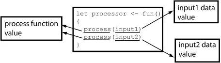
[image:2.595.324.524.334.424.2]A sample of hypercode using the language Process-Base, (Morrison, Balasubramaniam, Greenwood, Kirby, Mayes, Munro & Warboys 1999), is shown in Figure 1, where a function, processor, is defined which contains four hyperlinks. The mixture of text
Figure 1: Hypercode contains hyperlinks to existing values
and links is similar to a page of HTML viewed in a browser, the essential difference being that the hyper-links in hypercode point to live objects. In this exam-ple the links point to values, including functions, but
there is no distinction between them in the user inter-face: the difference has been abstracted over. Click-ing on a hyperlink gives the user a hypercode view of the value. To model sharing, any number of links are permitted to the same value, shown by the two separate links to theprocessfunction.
User interaction with hypercode has been defined by Zirintsis (2000), as a set of operations; these are:
explode Reify to reveal a hypercode view of the value pointed to by a hyperlink.
implode Inverse operation of explode which hides the view of the value.
evaluate hypercode Transform, compile, and exe-cute hypercode with visualisation.
edit Conventional editing facilities.
get root Returns the root of the object graph from a stable store.
This paper will concentrate on an implementation of theevaluate hypercode operation, which abstracts over the conventional programming tasks of compila-tion, linking, execution and debugging.
[image:2.595.61.289.636.701.2]A hypercode system can be considered as operat-ing within two domains: the entity and representation domains shown in Figure 2. Hypercode values exist
Figure 2: Hypercode in the entity and representation domains
and execute in the entity domain, but the user view of the values is in the representation domain. Switching between the two domains is achieved with reflection and reification. Theevaluate hypercodeoperation can be defined in terms of the two domains. It involves reflecting a hypercode representation into the entity domain where it executes. Then the execution and its result are reified to produce visualisations in the representation domain.
An important property of hypercode which un-derpins its usefulness in the evolutionary context is its ability to preserve the state and shared data of a system during evolution. This transpires because the hypercode source, which is a mixture of text and links to values in the store, is always avail-able. When the components in the system are de-composed, hyperlinks are maintained since they exist in the hypercode representation as well as in the ex-ecutable. Underlying persistence guarantees referen-tial integrity, which implies that the hyperlinks will always be accessible, therefore state and shared data can be preserved.
Balasubramaniam, Cimpan, Kirby, Mickan, Morri-son, Oquendo, RobertMorri-son, Seet, Snowdon, Warboys & Zirintsis 2003). When introspection is combined with compilation the technique known as structural reflection results, (Kirby, Morrison & Stemple 1998).
3 Composition and Decomposition
An essential property of evolutionary systems is the ability to decompose a running system into its con-stituent components, and recompose evolved or new components to form a new system, while preserving any state and shared data. In this context, the abil-ity of hypercode to capture closures allows parts of a system to be represented after decomposition without losing their state. It provides representations which can be used for both evolving the components and recomposing them into the new system.
The composition of a system S from components P and Q under rules has been defined by Morrison et al. (2000a) as:
P Q⇒SP Q
The ⇒ symbol represents the binding mechanism, which operates under the rules . For example, a compiler may merge a number of source files with the program to be compiled. The merging facility is the binder and the rules under which it operates deter-mine the order and scoping of the included files. De-composition is defined as the reverse of De-composition, giving the reversible equation:
P Q⇔SP Q
Hypercode provides the mechanism to realise the re-versible composition operation, since it offers intro-spection and the preservation of shared state and data throughout the evolutionary process. Normally, en-capsulated data in a program is difficult to access and breaking the encapsulation is an irreversible opera-tion.
[image:3.595.350.495.203.421.2]To further explain thecomposeanddecompose op-erations a scenario is modelled in Figure 3. The orig-inal system, in the bottom left of the figure, can be thought of as a composition of three filter components connected by two pipes. Two of the filter components refer to some data outside of the connected compo-nents, represented by the star shapes.
Figure 3: Compose and decompose operations
To evolve the system the first step is to decompose it into its components; note that the filter components still maintain their links to the data. Changes may then be effected on the components so that two of the filters are combined into a single filter. This new filter component still maintains links to the data referred to by the original filters. The three components can be composed to form a new system.
Figure 3 can be interpreted from both an tural and a process perspective. From the architec-tural perspective, the diagram captures the structure
of the current and evolved systems and the relation-ships between them in terms of which components are unchanged, modified or replaced. From a process per-spective the diagram captures how to evolve from the current to the evolved system: decompose into parts, replace some components and recombine in the new configuration.
4 Implementation
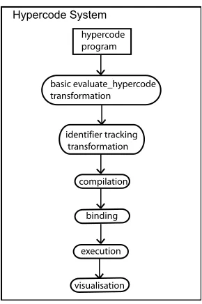
[image:3.595.63.288.538.649.2]evaluate hypercode is part of the hypercode system, the application which provides all the hypercode op-erations. It operates on the hypercode in four steps: transformation, compilation, binding and execution. Figure 4 shows the progress ofevaluate hypercode. A
Figure 4: evaluate hypercodeprocess
hypercode program is composed in the user inter-face. When evaluate hypercode is called, a program equivalent to the hypercode, but able to be processed by the conventional ProcessBase compiler, is gener-ated through source-to-source transformation. A sec-ond transformation is performed to insert the code to manageidentifier tracking. Then the transformed code is compiled, bound and executed. During exe-cution a visualisation is shown in the user interface, and afterwards the result is presented as a hypercode representation.
The two separate transformations in Figure 4 will be delineated: the basic transformation for evalu-ate hypercodegenerates an executable version of the hypercode program. The next transformation en-hances this by generating code to provide a reifica-tion of the hypercode execureifica-tion. Because identifiers in scope from the point of view of the user become hyperlinks during execution, the latter transforma-tion is referred to as identifier tracking. After the transformations, the generated program is compiled and executed by the hypercode system and the result of execution reified as a hypercode representation.
ProcessBase, the language used in the implemen-tation, has a number of properties which support the work in hypercode:
structural reflection The compiler is available as a library function.
first class functions Functions are first class values in the language.
All the hypercode operations have been imple-mented in ProcessBase, forming an environment in which to program hypercode. ProcessBase is also the language in which the user composes hypercode pro-grams. The programming environment consists of a hypercode system which accepts a request to perform an operation on some hypercode and returns the re-sult of the operation if applicable.
Figure 5 shows a short hypercode program as it appears to the user.
let filter <- fun(in stream: string) -> string spacer ++ in stream ++ spacer
filter(in pipe)
Figure 5: Hypercode representation viewed by the user
The same hypercode is represented as an XML string marked up with hyperlinks in Figure 6. The
let filter <- fun(in stream: string ) -> string <hl id="1">spacer</hl> ++ in stream
++ <hl id="1">spacer</hl>
filter(<hl id="2">in pipe</hl>)
Figure 6: Hypercode representation encoded as XML
code defines a function, filter, which concatenates its input with a spacer on each end and returns the re-sulting string. Both spacer hyperlinks point to the same data value. In the final line,filteris called with a parameterin pipe, which is a hyperlink. In the XML, the hyperlinks are marked up with <hl>tags which label them with ID strings. Each hypercode program is associated with a list of values in which the ID string is used to locate the value pointed to by this hyperlink.
[image:4.595.331.517.489.755.2]4.1 The evaluate hypercode Operation The conventional evaluate operation is comprised of compilation and execution, whereas evalu-ate hypercode involves transformation, compilation, binding, execution and visualisation. During the op-eration some hypercode is executed and hypercode is returned as the result. Figure 7 shows how evaluating the filterfunction produces a hyperlink to the result of execution.
Figure 7: evaluate hypercode operation
Figure 8 shows howevaluate hypercodecan be de-fined in terms of the functions applied to the hyper-code, where h is some hypercode. The compiler is used to reflect a transformed hypercode program; the
evaluate hypercode( h ) =
visualise ( execute ( compile ( transform ( h ) ) ) )
Figure 8: evaluate hypercodedefinition
result of a successful compilation is then executed; and the result of the execution reified, which produces a visualisation of the result for the user to view.
There are two generators used in the implemen-tation ofevaluate hypercode which will be focused on in the next sections. In order to display the result of
evaluate hypercode to the user, the hypercode must be compiled and executed. The task of the first gen-erator is to transform the hypercode into ProcessBase source so it can be processed by the conventional com-piler. The second generator carries out a transfor-mation for identifier tracking, where the hypercode execution is reified, and which can be used for debug-ging hypercode. Duringidentifier tracking, identifiers that come into scope during the execution turn into hyperlinks, enabling their values to be examined by the user.
4.2 Compiling Hyperlinks
Part of evaluating hypercode is linking the exist-ing values pointed to by the hyperlinks into the ex-ecutable code. The new implementation of evalu-ate hypercodefor ProcessBase uses the generative pro-gramming technique known as source-to-source trans-formation to do this. It makes no changes to the stan-dard compiler. A function is added which encloses the hypercode and takes a list of values as its parameter. When the transformed hypercode is executed, a list of values pointed to by the hyperlinks is passed to the function. The example code in Figure 5 will be used to show how the transformation progresses.
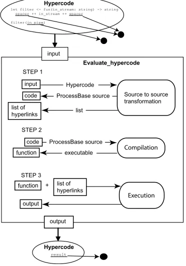
An overview of evaluate hypercode is depicted in Figure 9. A hypercode program, shown as it would be
rendered for the user, is input to evaluate hypercode. The program has three hyperlinks in it pointing to two values. evaluate hypercodeperforms the following steps:
1. Source-to-source transformation on the input produces transformed code and a list of hyperlinks.
2. Compiling the transformed code generates a function. 3. Projecting and executing the function with the list of
hyperlinks as its parameter gives a visualisation of evalu-ate hypercode.
The final outcome of evaluating the hypercode is out-put and rendered as a hyperlink.
In the first part of the transformation, Figure 10, each hyperlink in the hypercode is replaced with a new unique name: hl1 replaces spacer and hl2
re-let filter <- fun(in stream: string) -> string hl1 ++ in stream ++ hl1
[image:5.595.313.533.49.282.2]filter(hl2)
Figure 10: Hyperlinks replaced by names
places in pipe. Introducing these new identifiers into the code requires some type coercion. Most of the code generated by the following transformations is concerned with this task.
The values pointed to by the hyperlinks are asso-ciated with their new names in the list of hyperlinks which was referred to in Figure 9. This list is gener-ated by the hypercode system as part of step 1. In step 3, the compiled and transformed hypercode is called with the list as its parameter. Figure 11 shows the type of the list, which is a record. It hasid field to hold the name; and an entityfield, of the infinite union type any, to hold the value. Any data struc-ture could have been used. The use of a list is an implementation decision.
rec type list type is view[id: string; entity: any;
[image:5.595.310.544.318.560.2]next: loc[list type]]
Figure 11: Type of the list of hyperlinks
The code fragment in Figure 10 is made into legal ProcessBase code by including declarations for the new names, hl1 and hl2. The values associated with these identifiers will be part of the list of hyperlinks, and therefore have type any, so their specific types are also declared here. hl1andhl2are cast onto their types as they are declared.
In Figure 12 the type of the parameter list,list type
is defined; followed by the definition of a function,
getFromList, which will extract a value from the list, given its name. Next, the types of the hyperlinks are defined; in this case they are both string. This type information is acquired using thetypereplibrary func-tion in ProcessBase. Subsequently a project clause performs a cast from the infinite union type, which is the type of the value in the list, onto hl1 type; the same is done forhl2.
In Figure 13, the generator function is added around the hypercode; it takes as a parameter the table of hyperlinks,list. Thegenerator function is so called because it generates an executable version of the hypercode.
rec type list type ...
let getFromList <- fun(id: string) -> any .... !find the value in the list of parameters
! define the types of the hyperlinks type hl1 type is string
type hl2 type is string
!fetch the values from the list and cast
!them onto their correct types before assignment let hl1 <- project getFromList("hl1") as X onto
hl1 type: X
default: nil(hl1 type)
let hl2 <- project getFromList("hl2") as X onto hl2 type: X
default: nil(hl2 type)
let filter <- fun(in stream: string) -> string begin
hl1 ++ in stream ++ hl1 end
filter( hl2)
Figure 12: Declaring the new identifier
rec type list_type ...
let generator<-fun(list:list type) -> fun()->any{
let getFromList <- fun(id: string) -> any ...! get a value from the list
type hl1 type is string type hl2 type is string let hl1 <- project ... let hl2 <- project ...
type return_type is string
let wrapper <- fun() -> return type {
let filter <- fun(in stream: string) -> string hl1 ++ in stream ++ hl1
filter( hl2)
}
! generator returns a function which calls wrapper fun() -> any
any(wrapper())
}
generator
Figure 13: Adding thegeneratorfunction
generator needs to have a fixed type so it can be invoked from a fixed context in the hypercode system. Its return type isfun() → any, a function which re-turns a value of typeany: which can be explained by looking further down the code to the wrapper func-tion. This function wraps around the original hyper-code, so that it can later be executed alone without the overhead of projections during the execution of
en-closed in a function which returns a value of typeany. The final line in Figure 13 is generator, hence the re-sult of executing the code is the generator function itself.
In summary, when the hypercode system executes the code in Figure 13, it obtains the generator func-tion. The execution of generatorreturns a function, and executing this function returns the result of exe-cutingwrapper, which is a string, inside anany. Ex-ecuting the function returned bygeneratoris equiva-lent to executing the hypercode.
Having completed the transformation, the gener-ated code is compiled and executed - this is steps 2 and 3 in Figure 9. Figure 14 shows the section of code in the hypercode system which acts on the transformed hypercode. Step 2 is applying the
com-!call the compiler with code !(the transformed hypercode)
let compilation result <- compile(code)
!project the result of compilation onto the type !of generator
project compilation result.result as X onto fun() -> any: {
let Y <- X() !Y is the generator function
project Y as generator onto fun(list type) -> fun()-> any: {
let hypercode function <- generator(list) let hypercode result <- hypercode function() explode(hypercode result)
}
fun(list type) -> fun(): {
let hypercode function <- generator(list) hypercode function()
default: raise exception
} }
[image:6.595.321.521.146.340.2]default: raise exception
Figure 14: Compiling and executing the hypercode
piler to the transformed hypercode. The start of Fig-ure 14 shows the compiler being called withcode, the transformed hypercode, as its parameter. The com-piler returns a structure with the executable function in result. In the first project statement the result of compilation is projected onto type fun() → any and executed, which is the start of step 3. The execution returns Y, which is thegeneratorfunction, wrapped in an infinite union type. This is in turn projected onto the specific type ofgenerator, and then executed. The parameterlistpassed togeneratoris the list of hyper-links built up during the source transformation. Exe-cutinggeneratorgives a function,hypercode function, and executing this is equivalent to running the hyper-code. This gives the return value of the hypercode in-side hypercode resultwhich has typeany. To extract a value of the correct type from hypercode result, the hypercode operationexplode, which reifies a value, is used.
The second part of the project statement, whereY
is projected ontofun(list type)→fun(), is used when evaluating a hypercode program which does not re-turn a value. Thengeneratorreturns a function which returns nothing. The third part of the project state-ment raises an exception and is chosen when neither of the previous types matches the value, which would only occur if the hypercode system failed.
4.3 Identifier Tracking
Duringidentifier tracking, hypercode execution is an-imated and identifiers in scope from the user’s point of view become hyperlinks. The user may click on any identifier and see its value at that point in execu-tion. This paper concentrates on an animation which is only updated at user inserted breakpoints.
Figure 15 shows the user view of identifier track-ing on the functionhyphenate. This function declares
Figure 15: User view of identifier tracking
a string divider and concatenates it to the front of
in pipe. The black dot to the left of the hypercode indicates a breakpoint. In the first part of the figure, (a), execution, indicated by a horizontal line, has not yet begun and there are no hyperlinks in the code. In (b), execution continues down to the breakpoint and stops; the identifiers which are in scope,divider and
in pipe, become hyperlinks. After executing hyphen-ate, in (c), only the function call itself is still in scope and the other identifiers cease to be hyperlinks.
To implement identifier tracking, a generative pro-cess is applied. Code is inserted which will halt the execution at breakpoints and restart it on request; and turn identifiers into hyperlinks when they are in scope. All identifiers are made into potential hyper-links, which are only activated while in scope. As a result of this transformation, the code which executes is no longer identical to the hypercode that the user is viewing the execution of. Therefore, the system has two versions of the hypercode: an executing version and a separate version which appears to the user.
As part of evaluate hypercode, the system parses the hypercode and outputs these two versions. The process of producing each is explained in the following sections, which delineate the generation of the code viewed by the user, and the code which executes, re-spectively. During identifier tracking these two ver-sions communicate with each other to coordinate on breakpoints.
4.3.1 Producing a user view of identifier tracking
There are two essential elements of the hypercode that the user views during identifier tracking. Firstly, every identifier has the potential to be a hyperlink; and secondly, at a breakpoint, it can be established which identifiers should be hyperlinks. The rule is that an identifier turns into a hyperlink when it is in scope.
[image:6.595.62.297.212.451.2]its scope, as well as an ID string, to connect it with a value in the table when it becomes a hyperlink. Figure 16 shows how this information is included in the hypercode as XML. Each identifier is marked up
<hl id="divider00" scope="0:0">divider</hl> ++ <hl id="in pipe00" scope="0:0">in pipe</hl>
Figure 16: XML representation of the user view of identifier tracking
as a hyperlink, the attributes of which indicate its ID and scope. The code in Figure 16 is a sample of what is generated from a syntactic analysis of the hypercode from line 4 of Figure 15(a), where each identifier is replaced with a hyperlink.
The markup included in the hypercode allows the user interface to determine what view to show the user depending on the point of execution. When the code stops at a breakpoint, the user interface receives a message telling it which breakpoint has been reached. From this information the scope can be established, and hence the identifiers which are hyperlinks in that scope can be shown. Hyperlinks which were included as part of the composition of the hypercode will al-ways be hyperlinks.
4.3.2 Producing the executing version Source transformation to produce the executing ver-sion of the hypercode involves adding code for a num-ber of different purposes. Firstly, all the new hyper-links which have been added to the user view of the code need to be associated with existing values. This is done by including code after each declaration to add the newly created value to a list of values and hyperlink IDs. Therefore, when the user clicks on a hyperlink, the correct value can be discovered from its ID by looking in the table. The value can then be reified to display as hypercode to the user. Secondly, the source code for functions needs to be stored, so that the function values can later be reified. Unlike other data values, where the hypercode view can be generated from the value, function source code must be explicitly saved. Thirdly, code needs to be added at breakpoints to stop the execution and coordinate with the user view.
A step by step example of source code transforma-tion on the hyphenatefunction from Figure 15 is pre-sented. The transformation is performed during the same syntactic analysis which produced the hyper-code for the user interface described in the previous section.
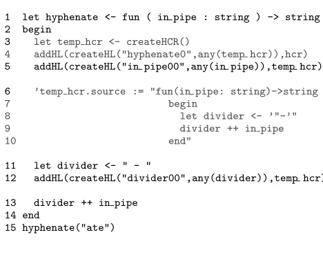
The first transformation is inserting code which will store the values of identifiers as part of the hyper-code representation, HCR, a data structure contain-ing the source code and links which represent a hyper-code program. In Figure 17, each identifier declara-tion in the hyphenate function is followed by a line which does this. The addHL function adds a hyper-link to the HCR. ThecreateHLfunction makes a new hyperlink from an ID, e.g. in pipe00, and a value, e.g. in pipe, which is cast as an infinite union type. If there are already hyperlinks in the code, added dur-ing the hypercode composition, they do not need to be added toHCRbecause they are already part of it. A hypercode representation, or HCR, is created for each function in the hypercode program, and added to the program’s HCR as a hyperlink. Identifiers within the function become hyperlinks in the func-tion’s HCR. Figure 18 shows the HCR, being created for hyphenate in line 3, and added to the program’s
let hyphenate <- fun ( in_pipe : string ) -> string begin
addHL(createHL("in pipe00",any(in pipe)),hcr) let divider <- " - "
addHL(createHL("divider00",any(divider)),hcr) divider ++ in_pipe
end
hyphenate("ate")
Figure 17: Creating hyperlink values and adding them to the HCR
HCR as a hyperlink in line 4. The source code for
hyphenate is stored in the HCR as a string in lines 6-10. Preserving the source code ofhyphenateallows a hypercode view of the function to be generated.
1 let hyphenate <- fun ( in pipe : string ) -> string 2 begin
3 let temp hcr <- createHCR()
4 addHL(createHL("hyphenate0",any(temp hcr)),hcr) 5 addHL(createHL("in pipe00",any(in pipe)),temp hcr)
6 ’temp hcr.source := "fun(in pipe: string)->string
7 begin
8 let divider <- ’"-’"
9 divider ++ in pipe
10 end"
11 let divider <- " - "
12 addHL(createHL("divider00",any(divider)),temp hcr)
13 divider ++ in pipe 14 end
[image:7.595.310.544.243.429.2]15 hyphenate("ate")
Figure 18: Creating a new HCR for the function
A function is added around the code which takes an HCR as a parameter. Figure 19 shows the defini-tion of the outer function. Later, outercan be
exe-let outer <- fun(hcr: loc[HCR]) begin
let hyphenate <- fun ( in_pipe : string ) -> string ...
end outer
Figure 19: outertakes an HCR as its parameter
cuted with an existing HCR in scope similar to what was done with the generatorfunction in section 4.2.
outeris returned at the end of the code so it can be executed later by the hypercode system.
The final stage of the transformation involves adding code which will stop the hypercode execution at the designated breakpoints and wake it up again on receipt of a message from the user. This is done using semaphores. On completion of the transforma-tion the code is compiled and executed using the same technique as forevaluate hypercode, which was shown in Figure 14.
in-Figure 20: Hypercode system, executing hypercode and user interface interact during identifier tracking
terface are within the hypercode system, they each have their own thread, so they are shown separately in the diagram. Communications between the user interface and the other two threads are in the form of messages, shown as dotted lines. The hypercode sys-tem and executing hypercode communicate through semaphores.
Figure 21 shows the portion of code in the hyper-code system which manages the interactions between the executing hypercode and the user interface. The
...
1. let sem <- newSemaphore(0) 2. let executing hypercode
<-start(fun();outer(hcr,sem))
3. sem.wait() ! wait for signal from hypercode 4. getMessage(restart) ! wait here for user message 5. sem.signal() ! restart hypercode
...
Figure 21: Hypercode system restarts the hypercode execution after a signal from the user
code in this figure is not part of the transformation, but part of the hypercode system which has generated the transformation. In line 1, a new semaphore ob-ject is created. The second line starts a new thread to execute the outerfunction, i.e. the hypercode, which has already been compiled by the time this code exe-cutes in the hypercode system. The definition of the
outer function has also been altered here to take a semaphore as its second parameter. Figure 22 shows the code which is added at this stage of the transfor-mation, and line 1 shows the new definition ofouter. Looking back to line 3 of Figure 21, it can be seen
1. let outer <- fun(hcr: loc[HCR]; sem: semaphore) 2. begin
3. let hyphenate <- fun(in_pipe: string)->string 4. begin
...
5. sendMessage(breakpoint_number,scope) 6. sem.signal() ! wake up main thread 7. sem.wait() ! suspend self
[image:8.595.78.248.41.172.2]... 8. end 9. outer
Figure 22: Adding semaphores to stop the code at breakpoints
that after starting the execution ofouter, the
hyper-code system waits. Now the execution passes to the code in Figure 22, which executes down to the break-point, at which stage it sends a message to the user interface, in line 5, to inform it which breakpoint it has stopped at and what the current scope is. This in-formation is inserted during the transin-formation when the syntax analyser can access the current scope. The user has defined where the breakpoints are. In line 6, the hypercode signals the semaphore which wakes up the main thread, and in the next line it suspends its own execution. The hypercode system in Figure 21 has been waiting on line 3 for the signal from the hypercode. Once it receives that, the hypercode ex-ecution has been suspended and the user is exam-ining the code halted at the breakpoint. When the user sends a message to restart the code, which is waited on in line 4, the hypercode system signals the semaphore, thereby restarting the execution of the hypercode thread.
4.4 Implementation Status
The current hypercode implementation for Process-Base includes the hypercode operations and the gen-erators described in this paper. The user interface is still under development.
5 Related Work 5.1 Hypercode
Apart from the work on hyper-programming sys-tems described in the introduction there are a few projects which have implemented programming sys-tems related to the hypercode environment. The Intentional Programming project at Microsoft Re-search, (Simonyi 1995) built a development environ-ment which operates overactive source: a graph data structure representing the program. The behaviour of the program source is implemented using meth-ods operating on this graph. Nodes of the graph can be elements from different programming languages, each node is associated with a declaration of inten-tionwhich corresponds to the syntax definition of the programming language. Identifier declarations are as-sociated with their uses in the source graph.
Other projects such as the CodeProcessor, (Vanter & Boshernitsan 2000) built at Sun Microsystems aim to improve programming environments by manipulat-ing source code to exploit the formal structure of the programming language. These tools can use infor-mation derived via linguistic analysis to offer services that are impractical for purely text-based tools. How-ever, they fall short of including live data values in the programming process.
5.2 Architectural evolution
There is a growing body of work on the subject of soft-ware evolution, where complex and dynamic softsoft-ware systems are of particular interest. These systems have emergent properties which can result in changes to the system becoming necessary after deployment. In addition, the software often operates within a chang-ing business environment. Lehman’s first law of soft-ware evolution, (Lehman 1996), states that a softsoft-ware system embedded in a real world domain must con-tinually change or becoming increasingly less useful. The changes are driven by the need to repair soft-ware faults, cope with new operating environments, and add or modify functionality.
[image:8.595.62.287.614.734.2]under various conditions of use. Some researchers ar-gue that software should be able to meet the needs of all users, (Kiczales, Lamping, Maeda, Keppel & McNamee 1993), which leads into work in compliant architectures, (Morrison, Balasubramaniam, Green-wood, Kirby, Mayes, Munro & Warboys 2000b). These architectures accommodate, and are thus com-pliant to, the needs of particular applications and users.
An explicit run-time representation of a system’s architecture can aid evolution of the system at run-time. An implementation of such a system is de-scribed in (Oreizy & Taylor 1998). ArchStudio is a tool suite that supports architecture-based develop-ment. Changes are made to an architectural model and then reified into implementation by a runtime architecture infrastructure. However, this system re-stricts the user to a particular architectural style.
6 Further Work
In future this work will be extended by incorporat-ing hypercode into the ArchWare system. Hypercode would provide an interface to the Architecture De-scription Language defined as part of the project. It would also provide the means to implement the
composeanddecomposeoperations which characterise evolution at the architectural level.
7 Acknowledgements
This work is supported by the EC Framework V project ArchWare (IST-2001-32360) and the Overseas Research Students Award Scheme (ORS).
8 Conclusion
This work shows the use of generative technology to implement a hypercode system. Two separate source-to-source transformations have been applied to a piece of hypercode to generate different visuali-sations of the hypercode evaluation. Compilation of hyperlinks was facilitated by the basic transforma-tion. The transformation for identifier tracking en-abled the user to view a representation of the hyper-code execution and access the values of identifiers in scope.
Generative technology facilitates an unlimited set of transformations on hypercode. These could in-clude: conversion into an XML Infoset; inclusion of dynamic traces; and customised display of data types. Generators for such purposes assume the input of properly formed hypercode and alter it to produce different visualisations and useful formats. Alterna-tively, the application of transformations to improp-erly formed hypercode can be considered, allowing the user to enter programs in any appropriate format. For example, mathematical formulae could be entered in a formula editor, or a graphical tool could assist in designing a program.
Also presented here were the benefits of hyper-code when applied to the evolution of software archi-tectures: because hypercode represents closure and offers a unified view of the system it can be used to underpin thecomposeanddecompose operations.
References
Czarnecki, K. & Eisenecker, U. (2000), Generative Programming: Methods, Tools, and Applica-tions, Addison-Wesley.
Farkas, A. & Dearle, A. (1994), ‘The Octopus model and its implementation’, Australian Computer Science Comm. — Proc. 17th Annual Computer Science Conf., ACSC16(1), 581–590.
Greenwood, M., Robertson, I. & Warboys, B. (2000), A support framework for dynamic organizations,
inR. Conradi, ed., ‘Proceedings of the 7th Euro-pean Workshop in Software Process Technology (EWSPT 2000)’, Vol. 1780 of Lecture Notes in Computer Science, Springer, Kaprun, Austria, pp. 6–20.
Greenwood, R., Balasubramaniam, D., Cimpan, S., Kirby, G., Mickan, K., Morrison, R., Oquendo, F., Robertson, I., Seet, W., Snowdon, B., War-boys, B. & Zirintsis, E. (2003), ‘Process sup-port for evolving active architectures’,9th Euro-pean Workshop on Software Process Technology (EWSPT 2003), Helsinki, Finland .
Kiczales, G., Lamping, J., Maeda, C., Keppel, D. & McNamee, D. (1993), The need for cus-tomizable operating systems,in ‘Proceedings of the Fourth Workshop on Workstation Operat-ing Systems’, IEEE Computer Society Techni-cal Committee on Operating Systems and Ap-plications Environment, IEEE Computer Society Press, pp. 165–169.
Kirby, G., Connor, R., Cutts, Q., Dearle, A., Farkas, A. & Morrison, R. (1992), Persistent hyper-programs,in‘Persistent Object Systems’, Springer-Verlag, pp. 86–106.
Kirby, G., Morrison, R. & Stemple, D. (1998), ‘Lin-guistic reflection in Java’, Software - Practice and Experience28(10), 1045–1077.
Lehman, M. (1996), Laws of software evolution re-visited,in‘5th European Workshop on Software Process Technology, EWSPT’, Nancy, France, pp. 108–124.
Morrison, R., Balasubramaniam, D., Greenwood, M., Kirby, G., Mayes, K., Munro, D. & Warboys, B. (1999), ProcessBase reference manual (ver-sion 1.0.6), Technical report, Universities of St Andrews and Manchester.
Morrison, R., Balasubramaniam, D., Greenwood, R., Kirby, G., Mayes, K., Munro, D. & Warboys, B. (2000a), ‘An approach to compliance in software architectures’,IEE Computing and Control En-gineering Journal, Special Issue on Informatics
11(4), 195–200.
Morrison, R., Balasubramaniam, D., Greenwood, R., Kirby, G., Mayes, K., Munro, D. & Warboys, B. (2000b), ‘A compliant persistent architecture’,
Software - Practice and Experience, Special Issue on Persistent Object Systems30(4), 363–386. Morrison, R., Connor, R., Cutts, Q., Dearle, A.,
Farkas, A., Kirby, G., McGettrick, R. & Zir-intsis, E. (1999), Current directions in hyper-programming, in ‘Lecture Notes in Computer Science 1755’, Springer-Verlag, pp. 316–340.
Oreizy, P. & Taylor, R. (1998), On the role of software architectures in runtime system reconfiguration,
in ‘Proceedings of the International Conference on Configurable Distributed Systems (ICCDS 4)’, Annapolis MD.
Vanter, M. L. V. D. & Boshernitsan, M. (2000), Dis-playing and editing source code in software en-gineering environments,in‘Second International Symposium on Constructing Software Engineer-ing Tools (CoSET2000)’.
Zirintsis, E. (2000), Towards Simplification of the Software Development Process: The Hyper-Code Abstraction, PhD, University of St An-drews.
Zirintsis, E., Dunstan, V. S., Kirby, G. N. C. & Mor-rison, R. (1999), Hyper-programming in Java,in