An Enhanced
dq
-Based Vector Control System
for Modular Multilevel Converters Feeding
Variable Speed Drives
Mauricio Espinoza,
Student Member,
IEEE, Roberto C ´ardenas,
Senior Member,
IEEE,
Matias Diaz,
Student Member,
IEEE, and Jon Clare,
Senior Member,
IEEE
Abstract—Modular Multilevel Converters (M2C) are
con-sidered an attractive solution for high power drive appli-cations. However, energy balancing within the converter is complex to achieve, particularly when the machine is operating at low rotational speeds. In this paper a new control system, based on cascaded control loops and a vector-power-voltage (vP V) model of the M2C, is proposed. The control system is implemented in a dq-synchronous frame rotating atωerad/s with the external loop regulating
the capacitor voltages using PI controllers. The internal loop controls the converter currents using PI and resonant controllers. In addition the control systems required to operate the machine at other points, i.e. at medium and high rotational speeds, are also discussed in this work. Experi-mental results obtained with a M2C-based drive laboratory
prototype with eighteen power cells are presented in this paper.
Index Terms—Modular Multilevel Converter, variable speed drives, low-frequency operation, voltage balancing.
I. INTRODUCTION
T
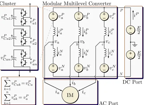
HE Modular Multilevel Converter (M2C) is a relatively new power converter topology originally proposed for high voltage dc (HVDC) transmission [1]–[4]. However, for drive applications, the M2C has several advantages whencompared to other high-power converters, particularly for quadratic torque-speed profile loads, where a better perfor-mance has been reported [5], [6]. Several publications, where experimental results are presented, have been discussed in the literature [7]–[20]. The topology of a high power drive based on a M2C is shown in Fig. 1. It is composed of an ac port, a
dc port and six ”clusters”. Each cluster has n cascaded cells and an inductor L. Each cell is composed of a half bridge circuit and its associated ”flying” capacitor C.
Because of the large number of flying capacitors, one of the important tasks of the control systems is to maintain the voltage in each capacitor operating within an acceptable range.
Mauricio Espinoza is with the Electrical Engineering Department, University of Costa Rica, San Pedro, Costa Rica (e-mail: mauri-cio.espinoza [email protected]),
Roberto C ´ardenas and Mat´ıas D´ıaz are with the Electrical Engineer-ing Department, University of Chile, Avenida Tupper 2007, Santiago, Chile (e-mail: [email protected], [email protected]).
[image:1.612.315.562.209.390.2]Jon Clare is with the Department of Electrical and Electronic Engi-neering, University of Nottingham, Nottingham University Park, Notting-ham, NG7, 2RD, (e-mail: [email protected]).
Fig. 1. Modular Multilevel Converter topology
This control target is difficult to fulfil when the electrical machine is operating at zero or low rotational speed [12], [13]. Therefore, for control purposes, the operating range of the M2C is usually divided into two modes: The High-Frequency
Mode (HFM) and the Low-Frequency Mode (LFM).
Control systems for both, HFM and LFM, have been pre-sented and experimentally validated in [9]–[12]. However, in these papers the control systems are not decoupled. Therefore, cross-couplings between control loops is possible, affecting the overall system performance. Moreover, in [9]–[12], [19] the regulation of the currents and voltages is realized using P or PI controllers. As is well known, these controllers are not appropriate for regulating the ac currents and voltages found in the M2C with zero steady state error [21]. In [19] a decoupled model of the M2C is proposed using a six-dimensional transformation of the converter signals to regulate the variables at each port and to perform the energy balance of the M2C. However, the effectiveness of the algorithms
proposed in [19] is difficult to evaluate because the presented experimental results do not show the tracking achieved for these signals in the proposed six-dimensional domain.
with or without third harmonic injection [12], [13], square wave [12] and hybrid mitigation signals [16], [22]. In all these publications, the set points for the regulation of the mitigation currents are predefined off-line. Therefore, the predetermined mitigation currents do not have any sort of closed loop adaptation capability which is required to compensate for possible changes in the parameters or operating points of the M2C-based drive. For instance off-line predefined mitigation
signals cannot compensate non-linearities (e.g. dead times issues in the converter cells); non-idealities or simplifications in the power converter model (e.g. neglected inductor voltage in the energy model); the difficulties associated with measuring the stator voltage at low rotational speeds, etc. Moreover in [12]–[16], [19], [22] P or PI controllers, implemented in the stationary frame, are utilised. As mentioned before, these controllers are not appropriate to regulate sinusoidal signals with zero steady state error.
To solve the aforementioned problems, this paper proposes a new control system for the operation of the M2C-based
drive. Moreover, to analyse the control system a vector-Power-Voltage (vP V) model is presented in this work. This model represents the dynamics of the topology shown in Fig. 1 using a compact notation with only four vector equations being required. Moreover, it is simpler to use this 4-equation modelling to propose, analyse, and implement conventional
dq-based vector control systems.
The proposed dq vector control system is based on a cas-caded architecture, where the outer loop drives the imbalances in the capacitor voltages to zero by modifying the set-point value for the circulating currents, which are regulated with resonant controllers implemented in a synchronous rotating frame. Using some minor modifications the proposed control scheme is suitable for operation in both the LFM and HFM.
The rest of this paper is organised as follows. Section II briefly discusses the conventional modelling of the M2C drive topology shown in Fig. 1. Section III discussed the proposed
vP V model and the vector control systems for operating at LFM and HFM. Section IV presents the experimental results obtained with a laboratory prototype. Finally, an appraisal of the proposed control systems is presented in the conclusions.
II. ANALYSIS OF THEM2C
A. Voltage-Current Model of the M2C
As often occurs in applications related to power converters, it is simpler to analyse the system using a different coordinate space. In this section the Σ∆αβ0 transformation (which is partly based on the work presented in [23]) is discussed. Considering the M2C shown in Fig. 1, the following currents
can be obtained as a function of the cluster currents by using the[C]Σ∆matrix, which considers the interaction of electrical variables among the converter poles:
iΣa iΣb i Σ c
ia ib ic = 1 2 1 2 1 −1
| {z }
[C]Σ∆
·
iPa iPb i P c
iN a iNb i
N c
(1)
where the lower row of the resultant current matrix contains the ac port currents and the upper row contains currents that
do not appear at the ac port, usually referred to as circulating currents [12], [24]. However, (1) can be post-multiplied by the transpose Clarke-transformation, [C]|αβ0, to consider the interaction of the electrical variables among the converter phases of the M2C and to get the independent components
of each kind of current, resulting in:
iΣ α iΣβ i
Σ 0
iα iβ i0 = 1 2 1 2 1−1
·
iPa iPb i P c
iN a iNb i
N c · 2 3 − 1 3 − 1 3 0 √1
3 − 1 √ 3 1 3 1 3 1 3 |
| {z }
[C]|
αβ0
= iΣ
α iΣβ 1 3i
P
iα iβ 0
(2) whereiΣ
0 = 1 3i
P and the zero sequence current isi 0= 0.
TheΣ∆αβ0transformation applied to (2) could be used to transform any2×3matrix fromPNabccoordinates toΣ∆αβ0
coordinates. Mathematically this is written as:
[X]Σ∆αβ0= [. C]Σ∆·[X]P Nabc ·[C]|αβ0 (3) Hence, Kirchhoff’s voltage law for every loop of Fig. 1 is applied to obtain the dynamic model of the cluster currents:
E 2
1 1 1 1 1 1
=
vP a vPb vPc
vNa vbN v N c
+Ld
dt
iP a iPb iPc
iNa iNb i N c
+
va vb vc
−va −vb −vc
(4)
and applying theΣ∆αβ0 transformation to (4) yields:
0 0 12E
0 0 0
= "
vΣ α vβΣ v
Σ 0
vα∆ v∆β v ∆ 0
#
+Ld dt
iΣα iΣβ 1 3i
P
iα iβ 0
+ 2
0 0 0
vα vβ v0
(5)
wherevα,vβ,iαandiβare theαβcoordinates of the voltages
and currents in the electrical machine, v0 is the common
mode voltage and iΣ
α and iΣβ are circulating currents which
are not present at any port. Using (5) it is simpler to propose and analyse an appropriate control system to regulate each independent current of the M2C shown in Fig. 1.
B. Power-Voltage Model of the M2C
The sum of the capacitor voltages in a cluster (i.e. the available cluster voltage) is related with its instantaneous power by the following expression [10], [25]:
d dt
vP
Ca vCbP vPCc
vNCa vCbN vNCc
| {z }
[V]P N Cabc
≈ 1
CvC∗
pP
a pPb pPc
pNa pNb pNc
| {z }
[P]P N abc
(6)
wherev∗
C is the voltage reference for the capacitor voltage in
each cell. Notice that the powers in (6) (in a-b-c coordinates) are calculated using the current and voltage of each cluster (e.g. pP
a =vPaiPa, pNa = vNaiNa, etc.). Moreover, in (6) it is
assumed that the capacitor voltages are well regulated with instantaneous values close tov∗C.
among the converter poles and phases [see (3)] as follows: d dt " vΣ Cα v Σ Cβ v Σ C0
vCα∆ vCβ∆ vC∆0
#
| {z }
[V]Σ∆ Cαβ0
≈ 1
Cv∗C
"
pΣ α pΣβ p
Σ 0
p∆α p∆β p∆0
#
| {z }
[P]Σ∆ αβ0
(7)
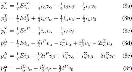
where the powers in Σ∆αβ0 coordinates could be derived from (5). After some manipulations yields:
pΣα =12Ei Σ
α−14iαvα+ 1 4iβvβ−
1
2iαv0 (8a)
pΣβ =12EiΣβ+14iβvα+14iαvβ−12iβv0 (8b)
pΣ0 =16EiP−1 4iαvα−
1
4iβvβ (8c)
p∆α =12Eiα− 2 3i
Pv
α−iΣαvα+iβΣvβ−2iΣαv0 (8d)
p∆β =12Eiβ− 1 32i
Pv
β+iΣβvα+iαΣvβ−2iΣβv0 (8e)
p∆0 =−iΣαvα−iΣβvβ−23iPv0 (8f)
The meaning of these variables is discussed in next sections.
III. PROPOSED CONTROL SYSTEM
A. Vector Power-Voltage Model of the M2C
In this paper a new Vector-Power-Voltage (vP V) model of the M2C is proposed. This model allows a simple analysis and implementation of control strategies using vector control algorithms. Defining the power flows and the total cluster voltages as vectors, e.g.pΣ
αβ=p Σ
α+jpΣβ,v Σ Cαβ =v
Σ
Cα+jvΣCβ,
etc., and using the conventional vector notation for the currents and voltages, the vector model of (8a)-(8f) is obtained as:
pΣαβ= 12EiΣαβ−1
4(iαβvαβ) c
−1
2v0iαβ (9a)
p∆αβ= 12Eiαβ−32iPvαβ− vαβiΣαβ c
−2v0iΣαβ (9b)
pΣ0 = 1 6Ei
P−1
4(vαβ◦iαβ) (9c)
p∆0 =− vαβ◦iΣαβ
−2 3i
Pv
0 (9d)
where the symbol “◦” represents the dot product between vectors and the superscript “c” stands for the complex conju-gated operator. In (9a), the vector pΣαβ represents the power flows between the converter phases. On the other hand the vector power p∆αβ [see (9b)] and the zero sequence powerp∆0
[see (9d)] represents power flows between the upper and lower poles of the converter. Finally the zero sequence power, pΣ 0
[see (9c)] is proportional to the power flow between the dc and ac ports and defines the change in the M2C total stored energy. The relationship between the powers of (9) and the voltages in Σ∆αβ0 coordinates is obtained from (7).
[image:3.612.77.300.154.276.2]If the control systems of the M2C-based drive depicted in
Fig. 1 achieve perfect regulation of the capacitor voltages, then it is concluded from (6) and (7) that in steady state the vector voltages in Σ∆αβ0 coordinates converge to:
vΣCαβ∗
=
v∆Cαβ∗
=v∆C0∗= 0, vCΣ∗0=nv∗C (10)
B. Analysis of the System Using thevP V Model for LFM
When the machine is operating atωe≈0rads−1, the stator
voltage applied is low. Using (7) and (9b) yields:
Cv∗Cdv
∆ Cαβ
dt ≈p
∆ αβ≈
1
2Eiαβ−2v0i Σ
αβ (11)
Analysing (11) is concluded that most of the low frequencyωe
power oscillations are produced by the termEiαβ, particularly
when high motor starting current is required. Moreover, if the stator voltage is not negligible, additional low frequency power oscillations are produced by the termiPvαβ inp∆αβ.
To avoid large voltage variations in the M2C capacitors, the low frequency power oscillations produced by Eiαβ and
iPvαβhave to be mitigated or eliminated fromp∆αβ. Therefore,
in this work a hybrid control strategy, based on the ac compo-nent of the common mode voltage (i.e.v˜0) and the circulating
current (i.e. ˜iΣ
αβ), is proposed to reduce the amplitude of
v∆
Cαβ during LFM operation. Thus, the set point value of the
circulating current˜iΣ
αβ is defined as: ˜iΣ∗
αβ=ke
j(θe−θ0)f(t) (12)
where k is a constant, θe = R
ωedt, with ωe as the output
frequency and θ0a phase angle. The term f(t)is defined as:
f(t) =Asin (ωmt) (13)
where the value ofωmis a degree of freedom, usually selected
to be relatively high compared to ωe. Additionally, ˜v∗0 is
defined as a square waveform of frequency ωm, i.e.: ˜
v∗0=V0sgn[f(t)] (14)
Using (12) and (14) is relatively simple to demonstrate that
˜
v0∗˜iΣ∗
αβhas a power term of frequencyωewhich could be used
to mitigate the low frequency power pulsations produced by the termsEiαβandvαβ in (9b). Ideally, these low frequency signals are completely eliminated when:
˜iΣ αβ=ke
j(θe−θ0)f(t) = 1 2V0
1 2Eiαβ−
2 3i
Pv αβ
f(t) (15) whereA=1.57is used in (13) as is discussed elsewhere [22]. In the following subsections the control systems required for voltage balancing and mitigation of the power oscillations are going to be discussed. They are analysed and designed using thevP V model depicted in (9a)-(9d).
C. Vector control of thev∆Cαβ voltage
1) At low rotational speed (LFM): As discussed in several
publications [12]–[16], [22] the most critical operating point of a M2C-drive is when the electrical frequency is low and the
machine is operating with a relatively high current. Moreover, if˜iΣ∗
αβis off-line calculated using (15), there are several issues
which can potentially hinder the correct mitigation of the low frequency voltage pulsation in the M2C capacitors. Some of
Current control loop Voltage control loop
Additional
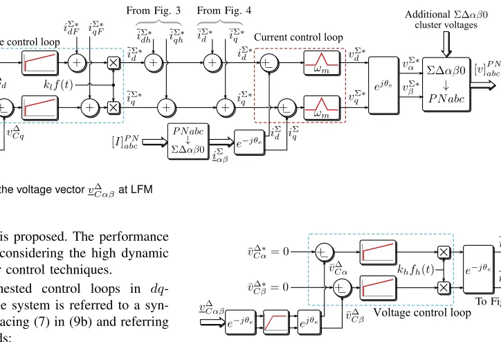
[image:4.612.178.540.52.299.2]cluster voltages From Fig. 3 From Fig. 4
Fig. 2. Proposed control system for the voltage vectorv∆
Cαβat LFM
for real time regulation of˜iΣ∗
αβ is proposed. The performance
of this control system is good considering the high dynamic typically achievable with vector control techniques.
To analyse the proposed nested control loops in dq -coordinates, the dynamics of the system is referred to a syn-chronous frame. Therefore, replacing (7) in (9b) and referring to a dq-axis rotating atωe yields:
CvC∗ hdv∆
Cdq dt +jωev
∆ Cdq
i
≈1
2Eidq−23i Pv
dq−2v0iΣdq (16)
Notice that in (16) one term producing relatively high fre-quency power oscillations has not been considered. These oscillations are almost completely filtered out by the M2C capacitors and its effects are negligible.
The proposed nested control system is shown in Fig. 2. The slower outer control loop regulatesv∆Cdq, and the internal faster control loop regulates the circulating current˜iΣ∗
dq. The voltage
vector v∆
Cdq, is controlled, with zero steady state error, using
PI controllers. The output of the external control loop is used to calculate the set-point for the circulating currents˜iΣ
dq. For
simplicity, the dq decoupling terms have not been considered in Fig. 2, but they can be added to both control loops.
In the external loop at the output of the PI controllers, two feed-forward compensation terms are considered. These terms are obtained by transforming (15) to the dq frame yielding:
˜iΣ∗ dqF = 21V0
1
2Eidq−23i Pv
dq
f(t) (17) and they correspond to the conventional feed-forward terms used in the control strategies reported in [12]. In this work these terms are used only to improve the dynamic performance of the voltage control loop. However, if (for instance) some of the components in (17) are misidentified, the PI controllers still ensure zero steady state error driving v∆
Cdq to zero (i.e.
eliminating theωefrequency component inv∆Cαβ).
Analysing (13) and (17) is concluded that thedqcirculating currents have sinusoidal components of frequencyωm.
There-fore, in this work resonant controllers are utilised to regulated these currents (see Fig. 2). Notice that the magnitude and phase of˜iΣ∗
αβ(i.e.kandθ0) are modified by the voltage control loop.
This is certainly an advantage over the conventional mitigation algorithm, where˜iΣ∗
αβis predetermined in advance and P or PI
controllers, implemented in the stationary frame, are used in the control system to balance the capacitor voltages [12], [19]. The output of the cascaded control systems shown in Fig.
[image:4.612.64.554.56.174.2]Voltage control loopTo Fig. 2
Fig. 3. Proposed control system for the voltagev∆
Cαβat HFM
2 are the clusters voltages in Σ∆αβ0 coordinates. These voltages are referred to the P N abc frame using the inverse
Σ∆αβ0 transformation in order to be processed by the cell balancing algorithm (see [26]). In this work the angle θe
is the rotor-flux angle of the vector controlled induction machine. However, the control system proposed in Fig. 2 can be orientated along any other vector rotating atωerads−1.
2) Operation at high rotational speed (HFM): The M2C is
operating in the HFM when the voltage oscillations in v∆Cαβ
are relatively small and the circulation of the mitigation cu-rrents is not longer required to maintain this voltage bounded.
In the HFM only the dc components ofv∆
Cαβ are regulated
to zero. Hence, PI controllers implemented in the stationary frame are used, as is shown in the control system in Fig. 3. To eliminate the components of frequencyωe fromv∆Cdq, a filter
is applied. Good performance and implementation simplicity have been obtained by using a high-pass filter implemented in a synchronous frame rotating at ωe (see Fig. 3). Notice that
high pass filters implemented in adq-frame are equivalent to notch filters in the stationary frame.
In previous work [19] it was proposed to add a positive and negative sequence current of frequencyωetoiΣαβ, to produce
a manipulable power flow in(vαβiΣαβ) c and (v
αβ◦iΣαβ). These
power flows were used to control the voltagesv∆
Cαβ andv ∆ C0
[see (9b) and (9d)]. However, when that methodology is used, the M2C control system could be affected by sudden variations
of the machine stator voltage, vαβ. In fact, cross-couplings
between the control systems could be introduced whenvαβ is
affected by intermittent load perturbations.
Hence, in this paper the power termv0iΣαβin (9b) is used to
balance the voltage vectorv∆Cαβ at HFM operation. Moreover, the common mode voltage˜v0is used to increase the maximum
LFM
HFM
To Fig. 2
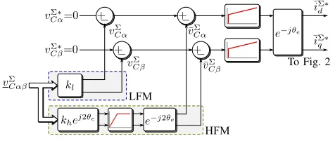
Fig. 4. Control system to regulate the voltagevΣ
αβ
˜
v0 and the functionfh(t)are defined as: ˜
v0=V0hsin 3θ∆αβ
, fh(t) = 2 sin 3θαβ∆
(18) whereθαβ∆ is defined as the electrical angle of the vectorv∆αβ=
v∆
α+jv∆β. It is important to clarify that the electrical angle used
to generate the common mode voltage (3θ∆
αβ) is not directly
derived from the voltages applied to the machine stator. This is because the phase shift introduced by the voltage drop in the cluster inductances is not negligible.
3) Transition between modes: A simple method is used
to switch between the low frequency and high frequency operating modes. Assuming thatωlis the highest frequency at
which (only) the LFM is used and the transition zone is from
ωl toωh, the following weighting factors are defined:
kl= 1−kh=
1 if|ωe|< ωl ωh−|ωe|
ωh−ωl ifωl≤ |ωe| ≤ωh 0 ifωh<|ωe|
(19)
These weighting factors are used to select the reference for current iΣdq∗ for either HFM or LFM (see Fig. 2 and Fig. 3).
For the experimental work presented in Section IV, the value of ωl is20π rads−1 (ωr≈500rpm) and ωh is equal to30π
rads−1 (ω
r≈750rpm). D. Control ofvΣ
αβfor the whole speed operating range
The voltagevΣ
Cαβis regulated by manipulatingp Σ
αβof (9a).
However, in pΣ
αβ there are not large low frequency power
oscillation when the machine is operating at ωe ≈ 0 and a
single control loop (see Fig. 4) with some minor modifications could suffice to operate in the LFM as well as the HFM.
The regulation of vΣ
Cαβ is achieved by introducing a dc
component in the circulating currents, iΣ∗
αβ, which affects the
powerEiΣ
[image:5.612.317.558.57.149.2]αβin (9a). The proposed control system is shown in
Fig. 4. At LFM, the voltagevΣ
Cαβis directly used as a feedback
signal, because most of its ac components are in the high frequency range which are filtered out by the cell capacitors. The only exception is the term(vαβiαβ)cthat produce a power
component of frequency2ωe. However, for LFM operation, the
magnitude of the stator voltage vαβ is small and the effects
produced by this power term are typically negligible.
To avoid the oscillations introduced by the 2ωe frequency
component at HFM operation, a notch filter (implemented synchronously) is applied to the feedback signal. The transition between modes is also realised using the weighting factors kl
LFM
[image:5.612.57.295.59.161.2]HFM
Fig. 5. Proposed control system for the voltagesvΣ
C0andv∆C0
and kh. The output of the PI controllers is a dc component
added to the circulating current referenceiΣαβ∗ (see Fig. 2).
E. Control of the voltagesvCΣ0andv∆C0
The voltages vΣ
C0 and v∆C0 are controlled by manipulating
the current iP and the common mode voltage, v
0. The
pro-posed control system, for both voltages, is shown in Fig. 5. The voltage vΣ
C0 is controlled by regulating the power
produced by the termEiP using the current iP [see (9c)] as
shown in the top side of Fig. 5. A feed-forwardiP
F term could
be included to improve the dynamic response when sudden variations in the ac output power are produced. This output power is represented by the term 14(vαβ◦iαβ)in (9c).
The voltage v∆
C0 is regulated by manipulating the power
produced by the term iPv
0 in (9d). This is achieved by
introducing a dc component in the common mode voltagev0as
shown at the bottom of Fig. 5. However, when the machine is operating at low rotational speed, the input power is negligible and the current iP is very low. Therefore in this case the
regulation ofv∆
C0 could require a large dc component in the
common mode voltagev0. To avoid this problem, in this paper
an alternative control method for LFM operation is proposed. It is relatively simple, with a low control effort, to add an ac (˜iP) current superimposed to the main dc input current. If
the current˜iP has the same frequency and phase off(t)[see (13)], then the voltagevC∆0could be regulated by manipulating the amplitude of (˜iP) and the mean value of the power term
˜iPv
0 in (9d). The proposed control system is shown in Fig.
5. Notice that a resonant controller tuned at ωm could be
required to regulate˜iP. Moreover the use of an ac component
superimposed to the main dc input current is dependant on the capacity of the dc power supply (feeding the M2C) to withstand operation with ac current components.
The selection of the control systems for HFM/LFM opera-tion is again realised by using the weighting factors of (19).
IV. EXPERIMENTAL SET-UP AND RESULTS
In Fig. 6a the experimental system implemented to validate the proposed control strategy is shown. In addition a picture of the experimental prototype is shown in Fig. 6b.
The M2C prototype is fed by a dc-link created by a
six-pulse diode rectifier bridge and filter capacitors. The M2C
(a) System configuration
Converter phase
Control platform
Induction machine
PMG
[image:6.612.54.297.61.345.2](b) Experimental system
Fig. 6. Description of the laboratory prototype
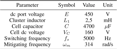
TABLE I
SET-UP PARAMETERS FOR THE18CELLSM2C-DRIVE
Parameter Symbol Value Unit
dc port voltage E 450 V
Cluster inductor L1 2,5 mH
Cell capacitor C 4700 µF
Cell dc voltage VC 160 V
Switching frequency fs 5000 Hz
Mitigating frequency ωm 314 rad/s
emulating a quadratic torque-speed load. For the implemen-tation of the indirect vector-control system [27], a position encoder of 10.000 pulses per revolution is affixed to the induction machine. Hall effect transducers are used to measure the dc-link voltage, the capacitor voltage of the 18 cells and the cluster currents. To control the system a platform based on two FPGA boards (Actel ProASIC3), 40 14-bit AD channels and the DSP Texas Instrument TMS320C6713 is used. Optical fibres are used to transmit the switching signals. The experimental parameters are summarized in Table I. All the control systems have been tuned using frequency domain linear control tools. The controllers are designed with the same tuning parameters to allow a fair comparison between different control methodologies.
A. Experimental results considering operation atωr= 0
For this test the rotor of the induction machine is mechani-cally locked and the stator currents are regulated toid≈2.2A
andiq=10A. This is a very demanding condition for the M2C
control system considering that the electrical frequency (close
to1.6Hz) is equal to the slip frequency. Two control system have been implemented to obtain the experimental results shown in Fig. 7. In both cases, the functionf(t)was defined as in (13) and the common mode voltage waveform was changed to a trapezoidal shape, with the edges of the 50Hz trapezoidal wave varying between−100%to 100%of the peak value in approximately 1ms. With this modification, the performance of the proposed control systems to operate when variations are produced in the M2C system is validated.
To allow a fair comparison between different control methodologies, all the nested control loops discussed in this work have been designed using identical tuning algorithms. Firstly, for the inner control loops (see Fig. 2), the controller parameters have been calculated by solving the following constrained optimisation problem:
min λ
∞ X
h=0
|e(hTs)| such that:MS = 2 (20)
whereλis the vector that contains the controller parameters,
e is the tracking error, Ts the sampling time and Ms is the
sensitivity function [28]. Notice that a system with MS ≤2
is usually considered very robust [28], [29].
Secondly, the parameters of the outer controllers are cal-culated by solving the following constrained optimisation problem:
min λ
∞ X
h=0
|y(hTs)−y∗(hTs)|such that:MS = 2 (21)
where y(hTs) is the system response and y∗(hTs) is the
desired response, which is usually selected to fulfil a pre-defined control bandwidth. The main advantage of using the tuning procedures depicted in (20) and (21), is that identical loop robustness is achieved for both, the conventional and the proposed methodology.
In Fig. 7a the results obtained by implementing the con-ventional control strategy reported in [12], [19] are shown. In this case the mitigation currents are off-line calculated using (15) and the control systems are based on PI controllers implemented in the stationary frame. On the other hand, the results obtained by the mitigation currents regulated using the proposed control strategy are shown in Fig. 7b.
As shown in Fig. 7, the peak to peak value of each capacitor voltage is reduced in 55% from approximately 11.9V to 6.6V when the proposed mitigating method is applied. Notice that this reduction produces an increase of 11% in the cluster peak-to-peak currents (from 34.4A to 38.3A), because in this case the feed-forward currents of (15) were underestimated. Both stator machine currents depicted in Fig. 7 (22.3A peak-to-peak) shows little distortion and are well regulated.
[image:6.612.79.270.403.484.2](a) (b)
[image:7.612.58.293.233.360.2]Fig. 7. M2C static performance at LFM. (a) stationary frame controllers (conventional methodology). (b) proposed control system. Blue: capacitor voltage (20 V/Div), yellow and green: cluster currents (15 A/Div), red: machine current (15 A/Div), pink: phaseacirculating current (15 A/Div).
Fig. 8. M2C signals applying the proposed control system. Blue: capacitor voltage (20 V/Div). green: line to line voltage (200 V/Div), red: machine current (15 A/Div), yellow: cluster voltage (250 V/Div).
2 3 4 5 6 7 8 Frequency (Hz) 1
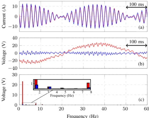
Fig. 9. Comparison of mitigation schemes. (a) iΣ
α. (b)vCα∆ . (c)v∆Cα
Fourier Spectrum. Blue:dq-based control, red: stationary frame control.
the proposed control system is able to reduce the capacitor voltage oscillations even if the waveform of v˜0 defined in
(14) is modified. As explained before the dq-based voltage control loop regulates with zero steady state error the signals of frequencyωepresent in the voltagev∆Cαβ, even if variations
in the M2C system are produced.
Finally an amplify view of some of the signals correspon-ding to the test of Fig. 7 are shown in Fig. 9. In Fig. 9a
both circulating currents are shown, i.e. that obtained from the conventional control method and the one obtained with the proposed control method of Fig. 2. The circulating currents have similar phase and different peak values. Fig. 9 (b) shows the voltage vCα∆ achieved with both control methodologies. Notice that for the conventional control system, the 1.6Hz oscillations are not eliminate from the capacitor voltage. The Fourier analysis of the frequency components inv∆
Cα, for both
control methodologies, is shown in Fig. 9. For the conventional control methodology there is a 20V component atf ≈1.6Hz, on the other hand the proposed control method has a 0.7V component at the same frequency.
B. Dynamic performance of the proposed control system
1) Performance considering step changes in the machine
currents: The experimental results considering step changes
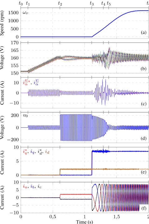
in the machine currents are shown in Fig. 10. For this test is considered that initially all the capacitors are discharged and the control and start-up of the M2C is realised in four stages
(t0=0s, t1=0.1s,t2=0.6s, t3=1.1s). In the first stage,[t0→t1]
(see at top of Fig. 10), the eighteen M2C cells (3 per cluster) are charged to 150V imposing a duty cycle of50%, (E = 450V). During the second stage,[t1→t2], the control
loops to regulate the voltagesvΣ Cαβ, v
∆ Cαβ,v
Σ C0 andv
∆ C0 are
enabled and the cell voltage set-point is changed linearly from 150V to 160V (see Fig. 10(b)). In this stage a small sinusoidal component of 50Hz is superimposed in the dc input current to facilitate the regulation ofv∆
C0. Moreover, as shown in Fig.
10(c) and Fig. 10(d), circulating current and common mode voltage are imposed in the system.
A step in the the reference of the machine magnetisating current is realised in the third stage,[t2→t3]andi∗d is set to 2.2 A (see Fig. 10(e) and Fig. 10(f)). After this step change, the proposed mitigating algorithm increases the common mode voltage and the magnitude of the circulating currents to maintain the M2C capacitor voltages well regulated.
The last stage,[t3→t4], is the machine start-up by
[image:7.612.54.292.410.599.2]Time (s)
Fig. 10. Set-up response to step changes in the machine currents. (a) Machine speed, (b) capacitor voltages, (c) Circulating current iΣα, (d)
desired common mode voltage, (e) ac port current (dq-frame), (f) ac port current (abc-frame).
The transition mode (TM) is defined between 10Hz-15Hz. In this mode the amplitude of iΣ
αβ is reduced and the
magnitude of the capacitor voltage oscillations increases to approximately ±4.44% of the nominal value (160V). When HFM operation is achieved, the circulating currents required are of relatively small amplitude balancing the energy in the M2C cells. In addition, for HFM operation the current iP is
relatively large and, due to this, a low dc component in the common-mode voltage is enough to maintain the voltage vC∆0
well regulated (see (9d)).
2) Dynamic performance considering a ramp variation in
ω∗r: To test the performance of the M2C-based drive in the
whole speed range, including zero-speed crossing operation, the rotational speed profile shown in Fig. 11(a) is applied to the induction machine. The machine is accelerated from 0 to
±1700 rpm with a slope of ±1800 rpm/s (see Fig. 11(a)). During LFM operation (below 10 Hz), a small ac component is superimposed in the dc input current to facilitate the regulation of v∆C0 (see Fig. 11(c) and Fig. 11(i)). Therefore some noise and oscillations are present in this current which are also related to the application of the common mode voltage. However, this is not a problem since the motor currents are not
LFM TM HFM TM LFM TM HFM TM LFM
(a)
(b)
(c)
(d)
(e)
(f)
(g)
(h)
(i) (c)
Fig. 11. System response to a ramp speed variation. (a) machine speed, (b) Total cluster voltages, (c) dc port current, (d) ac port current (dq
frame), (e) ac port currents (abcframe), (f)vΣ
Cαandv
Σ
Cβvoltages, (g) v∆
CαandvCβ∆ voltages, (h)vΣC0voltage, (i)v∆C0voltage.
affected (see Fig. 11(d) and Fig. 11(e)). Moreover, in this work is assumed that the dc port power supply can safely operate with (small) ac signals superimposed in iP.
In Fig. 11(g) theαβcomponents of the voltage vectorv∆ Cαβ
[image:8.612.54.293.54.412.2]When the transition zone is reached, the output signals of the LFM/HFM control systems are weighted up by the factors kl and kh defined in (19). During this transition the
oscillations of the cluster voltages are less than 30V peak-to-peak, representing a variation of±3.1%respect to the nominal value (3v∗C= 480V). During HFM operation, neither the ac component iniP nor the mitigating signals of (15) are applied.
Therefore, only the dc components of theΣ∆αβ0voltages are regulated. Moreover, the amplitude of the oscillations in the
Σ∆αβ0voltages decreases whenωrincreases. Therefore they
are relatively simpler to control. This is shown in Fig. 11(f) to Fig. 11(h) (depicting the voltagesvΣCαβ,v∆Cαβ,vCΣ0 andvC∆0). From the experimental results depicted in Fig. 11 is also concluded that the magnitudes of the oscillations produced when the machine is regenerating energy to the dc-link power source are smaller than those produce when the machine is motoring. This is because, for this test, the amplitudes of the machine currents and iP current are reduced during regeneration.
To the best of our knowledge this is the first time that regenerative and zero-speed crossing operation of a M2
C-based drive are experimentally implemented using a vector-controlled induction machine fed by a M2C.
V. CONCLUSION
In this paper a new and comprehensive vector-power-voltage (vP V) model of the M2C-based drive has been presented.
Using this model is simple to analyse the converter dynamics and it can be used to design and implement vector control strategies to balance the power converter, mitigate low fre-quency voltage oscillations, regulate the input/output energy transfer, etc.
Using the vP V model, a novel dq-based vector control strategy for LFM operation has been presented, analysed and experimentally validated in this paper. This control methodo-logy balances the capacitor voltages, as well as mitigates the low frequency (ωe) capacitor voltage oscillations using nested
control loops implementing PI and resonant controllers. The proposed modelling and vector control systems have also been applied to HFM operation. In all the cases, i.e. LFM and HFM operation, decoupled control of the voltages in theΣ∆αβ0-space is achieved by using circulating currents and common mode voltage of different frequencies. All the control strategies proposed in this paper have been analytically discussed and experimentally validated using a M2C-based
drive prototype. The dynamic and steady state performance of the proposed control methodologies have been tested, con-sidering M2C starting-up, step changes in both the torque and magnetising currents, speed-ramps, zero-speed crossing test, motoring and generating operation, rotor-locked operation, etc. In all the cases the performance achieved has been excellent. When compared to the control strategies reported in the literature, the proposed control system produces a higher computational burden, which is mostly required to implement several controllers, and to transform current and voltage sig-nals from abc coordinates to Σ∆αβ0 and dq coordinates. However this extra computational burden can be easily handled
by a modern DSP, e.g. in this work the implementation of the whole control system for an 18-cell converter, has been relatively simple to realise using a low cost commercial DSP augmented by FPGFA boards.
REFERENCES
[1] M. Glinka and R. Marquardt, “A new AC/AC-multilevel converter family applied to a single-phase converter,,” inPower Electronics and Drive Systems, 2003. PEDS 2003. The Fifth International Conference on, vol. 1, DOI 10.1109/PEDS.2003.1282669, Nov. 2003, pp. 16–23. [2] M. Glinka and R. Marquardt, “A new AC/AC multilevel converter
fam-ily,”IEEE Trans. Ind. Electron., vol. 52, DOI 10.1109/TIE.2005.843973, no. 3, pp. 662–669, Jun. 2005.
[3] S. Debnath, J. Qin, and M. Saeedifard, “Control and Stability Analysis of Modular Multilevel Converter Under Low-Frequency Operation,”IEEE Trans. Ind. Electron., vol. 62, DOI 10.1109/TIE.2015.2414908, no. 9, pp. 5329–5339, Sep. 2015.
[4] M. Perez, S. Bernet, J. Rodriguez, S. Kouro, and R. Lizana, “Circuit Topologies, Modeling, Control Schemes, and Applications of Modular Multilevel Converters,” IEEE Trans. Power Electron., vol. 30, DOI 10.1109/TPEL.2014.2310127, no. 1, pp. 4–17, Jan. 2015.
[5] Y. Okazaki, W. Kawamura, M. Hagiwara, H. Akagi, T. Ishida, M. Tsukakoshi, and R. Nakamura, “Experimental Comparisons Between Modular Multilevel DSCC Inverters and TSBC Converters for Medium-Voltage Motor Drives,” IEEE Trans. Power Electron., vol. PP, DOI 10.1109/TPEL.2016.2562103, no. 99, pp. 1–1, 2016.
[6] K. Ilves, L. Bessegato, and S. Norrga, “Comparison of cascaded multi-level converter topologies for AC/AC conversion,” inPower Electronics Conference (IPEC-Hiroshima 2014 - ECCE-ASIA), 2014 International, DOI 10.1109/IPEC.2014.6869722, May. 2014, pp. 1087–1094. [7] B. Tai, C. Gao, X. Liu, and Z. Chen, “A Novel Flexible Capacitor
Voltage Control Strategy for Variable-Speed Drives With Modular Multilevel Converters,” IEEE Trans. Power Electron., vol. 32, DOI 10.1109/TPEL.2016.2535463, no. 1, pp. 128–141, Jan. 2017. [8] J. J. Jung, H. J. Lee, and S. K. Sul, “Control Strategy for Improved
Dy-namic Performance of Variable-Speed Drives With Modular Multilevel Converter,”IEEE Trans. Emerg. Sel. Topics Power Electron., vol. 3, DOI 10.1109/JESTPE.2014.2323955, no. 2, pp. 371–380, Jun. 2015. [9] M. Hagiwara, K. Nishimura, and H. Akagi, “A Medium-Voltage Motor
Drive With a Modular Multilevel PWM Inverter,” IEEE Trans. Power Electron., vol. 25, no. 7, pp. 1786–1799, Jul. 2010.
[10] H. Akagi, “New trends in medium-voltage power converters and mo-tor drives,” in Industrial Electronics (ISIE), 2011 IEEE International Symposium on, DOI 10.1109/ISIE.2011.5984128, Jun. 2011, pp. 5–14. [11] N. Thitichaiworakorn, M. Hagiwara, and H. Akagi, “Experimental
Verification of a Modular Multilevel Cascade Inverter Based on Double-Star Bridge Cells,”IEEE Trans. Ind. Appl., vol. 50, no. 1, pp. 509–519, January-February 2014.
[12] M. Hagiwara, I. Hasegawa, and H. Akagi, “Start-Up and Low-Speed Operation of an Electric Motor Driven by a Modular Multilevel Cascade Inverter,”IEEE Trans. Ind. Appl., vol. 49, no. 4, pp. 1556–1565, July-August 2013.
[13] A. J. Korn, M. Winkelnkemper, and P. Steimer, “Low Output Frequency Operation of the Modular Multi-Level Converter,” inEnergy Conversion Congress and Exposition (ECCE), 2010 IEEE. IEEE, Sep. 2010. [14] A. Antonopoulos, L. ¨Angquist, S. Norrga, K. Ilves, L. Harnefors, and
H.-P. Nee, “Modular Multilevel Converter AC Motor Drives With Constant Torque From Zero to Nominal Speed,”IEEE Trans. Ind. Appl., vol. 50, DOI 10.1109/TIA.2013.2286217, no. 3, pp. 1982–1993, May. 2014. [15] B. Li, S. Zhou, D. Xu, D. Xu, and W. Wang, “Comparative study of the
sinusoidal-wave and square-wave circulating current injection methods for low-frequency operation of the modular multilevel converters,” in
2015 IEEE Energy Conversion Congress and Exposition (ECCE), DOI 10.1109/ECCE.2015.7310324, Sep. 2015, pp. 4700–4705.
[16] S. Debnath, J. Qin, and M. Saeedifard, “Control and Stability Analysis of Modular Multilevel Converter Under Low-Frequency Operation,”IEEE Trans. Ind. Electron., vol. 62, DOI 10.1109/TIE.2015.2414908, no. 9, pp. 5329–5339, Sep. 2015.
[18] J. Kolb, F. Kammerer, and M. Braun, “Dimensioning and design of a Modular Multilevel Converter for drive applications,” in Power Electronics and Motion Control Conference (EPE/PEMC), 2012 15th International, DOI 10.1109/EPEPEMC.2012.6397380, Sep. 2012, pp. 1–8.
[19] J. Kolb, F. Kammerer, M. Gommeringer, and M. Braun, “Cascaded Control System of the Modular Multilevel Converter for Feeding Variable-Speed Drives,” IEEE Trans. Power Electron., vol. 30, DOI 10.1109/TPEL.2014.2299894, no. 1, pp. 349–357, Jan. 2015. [20] S. Du, B. Wu, K. Tian, N. R. Zargari, and Z. Cheng, “An
Ac-tive Cross-Connected Modular Multilevel Converter (AC-MMC) for a Medium-Voltage Motor Drive,”IEEE Trans. Ind. Electron., vol. 63, DOI 10.1109/TIE.2016.2547875, no. 8, pp. 4707–4717, Aug. 2016. [21] R. Cardenas, C. Juri, R. Pena, J. Clare, and P. Wheeler, “Analysis
and Experimental Validation of Control Systems for Four-Leg Matrix Converter Applications,” IEEE Trans. Ind. Electron., vol. 59, DOI 10.1109/TIE.2011.2158041, no. 1, pp. 141–153, Jan. 2012.
[22] M. Espinoza, A. Mora, M. Diaz, and R. C´ardenas, “Balancing en-ergy and low frequency operation of the Modular Multilevel Con-verter in Back to Back configuration,” in Ecological Vehicles and Renewable Energies (EVER), 2015 International Conference on, DOI 10.1109/EVER.2015.7113005, Mar. 2015, pp. 1–9.
[23] F. Kammerer, M. Gommeringer, J. Kolb, and M. Braun, “Energy balancing of the Modular Multilevel Matrix Converter based on a new transformed arm power analysis,” inPower Electronics and Applications (EPE’14-ECCE Europe), 2014 16th European Conference on, DOI 10.1109/EPE.2014.6910939, Aug. 2014, pp. 1–10.
[24] Y. Wan, S. Liu, and J. Jiang, “Generalised analytical methods and current-energy control design for modular multilevel cascade converter,”
IET Power Electronics, vol. 6, DOI 10.1049/iet-pel.2012.0494, no. 3, pp. 495–504, Mar. 2013.
[25] H. Akagi, S. Inoue, and T. Yoshii, “Control and Performance of a Transformerless Cascade PWM STATCOM With Star Configuration,”
IEEE Trans. Ind. Appl., vol. 43, DOI 10.1109/TIA.2007.900487, no. 4, pp. 1041–1049, Jul. 2007.
[26] Y. Okazaki, H. Matsui, M. M. Muhoro, M. Hagiwara, and H. Akagi, “Enhancement on capacitor-voltage-balancing capability of a modu-lar multilevel cascade inverter for medium-voltage synchronous-motor drives,” in 2015 IEEE Energy Conversion Congress and Exposition (ECCE), DOI 10.1109/ECCE.2015.7310550, Sep. 2015, pp. 6352–6359. [27] R. Cardenas, R. Pena, J. Clare, and P. Wheeler, “Analytical and Expe-rimental Evaluation of a WECS Based on a Cage Induction Generator Fed by a Matrix Converter,”IEEE Trans. Energy Convers., vol. 26, DOI 10.1109/TEC.2010.2083666, no. 1, pp. 204–215, Mar. 2011.
[28] A. G. Yepes, F. D. Freijedo, ´O. Lopez, and J. Doval-Gandoy, “Analysis and Design of Resonant Current Controllers for Voltage-Source Con-verters by Means of Nyquist Diagrams and Sensitivity Function,”IEEE Trans. Ind. Electron., vol. 58, DOI 10.1109/TIE.2011.2126535, no. 11, pp. 5231–5250, Nov. 2011.
[29] B. Kristiansson and B. Lennartson, “Robust and optimal tuning of PI and PID controllers,”IEE Proceedings - Control Theory and Applications, vol. 149, DOI 10.1049/ip-cta:20020088, no. 1, pp. 17–25, Jan. 2002.
Mauricio Espinoza(S’15) was born in Alajuela, Costa Rica. He received the B.Sc. and Lic. de-grees in electrical engineering from the Univer-sity of Costa Rica in 2010 and 2012 respectively. From 2010-2014 he was a lecturer in the Uni-versity of Costa Rica. Actually, he is pursuing a Ph.D. degree at the University of Chile, Chile. During his career, he has worked in research projects related to Modular Multilevel Conver-ters, machine modelling and control systems for power electronics.
Roberto C ´ardenas (S’95-M’97-SM’07) was born in Punta Arenas Chile. He received his B.Sc. degree from the University of Magallanes, Chile, in 1988 and his Msc. and Ph.D degrees from the University of Nottingham in 1992 and 1996 respectively. From 1989-1991 and 1996-2008 he was a lecturer in the University of Maga-llanes Chile. From 1991 to 1996 he was with the Power Electronics Machines and Control Group (PEMC group), University of Nottingham, United Kingdom. From 2009-2011 he was with the Elec-trical Engineering Department, University of Santiago. He is currently a professor of power electronics and drives in the Electrical Engineering Department, University of Chile, Chile. His main interests are in control of electrical machines, variable speed drives and renewable energy systems.
Mat´ıas D´ıaz(S’15) was born in Santiago, Chile. He received the B.Sc. and the M.Sc. degrees from the University of Santiago of Chile in 2011. Currently, he is pursuing a dual Ph.D. degree at the University of Nottingham, U.K., and at the University of Chile, Chile. From 2013 to 2015 he was sub-director of the School of Engineering at Duoc UC. Currently, he is a Lecturer at the Uni-versity of Santiago of Chile. His main research interests include the control of Wind Energy Conversion Systems, Multilevel Converters, and renewable energy systems.