--,
(
•
; a··.
:'I:'I'1llrrTT. ~
. ~~~
Q001/D DISK CONTROLLER
TECHNICAL MANUAL
(MSCP COMPATIBLE)
3545
Harbol'Boulevard.. tosta Mesr,"Califomia 92626 (714) 662-5600 TWX 910-595-2521
.'
.
,("
EMULEX PRODUCT/MANUAL REVISION HISTORY
PROM A62x1, Location U43
•
PROMA62x DESCRIPTION MANUAL PIN
A,B,C,D, QD01/Dwith QD0151001-OO,
E,F,G optional diagnostics QD0151002-00
Hand QD01/D with firmware- QD0151003-00
above resident diagnostics ,
This manual has been extensively revised to incorporate changes to support the Firmware-Resident Diagnostics (FoR.D.) that have been added to the Revision H controller firmware PROM. Due to the nature of these firmware changes, a QD01/Q,with'a Revision H and above firmware PROM will
no longer operate with previously supplied diagrtqstic\aoftware. In addition, some of the ODT functions (NOVRAM loading commands and Format Drive command) previously available are no longer available.
All of the functionality-that was provided by software diagnostics and ODT commands has been incorporated in F.RoD: Be certain that your manual is appropriate for the revision level of your controller firmware, as noted in the table aboveo This firmware is easily identified by the la"el at U430
WARNING
This equipment generates, uses and can radiate radio frequency energy, ." and if not installed and used in accordance with the technical manual,
may ca~i"terference to radio communications. It has been tested and .. ' found to comply with the limits for a Oass A computing device pursuant
to Subpart J-of Part 15 of Federal Communications Commission (FCC) Rules, which· are designed to provide reasonable protection against such interference when operating in a commercial environment~ Operation of this equipment in a residential area is likely to cause interference in which case the user'at his own expense will be required to take whatever measures may be required to correct the interference.
Copyright (c) 1988 Emulex Corporation
The information in this manual isJor information~purposes and-is subject to change without notice .
• ~ <./f""~
"
Emulex Corporation assumes no responsibility for any errors which may appear in the m~ual.
"'''--Printed in U.S.A.
1 The small x indicates the PROM's revision level letter: A, B, C, etc.
,/,r--.(
'-,'/
-/ {
'",,-/,-
--(
ONE 1.1 1.2 1.2.1 1.3 1.41.5
1.5.1
1.5.21.5.3
1.5.41.5.5
1.5.6
1.5.7
1.5.8
1.5.9
1.5.101.5.11
1.6 1.6.1 1.6.2C·
'tWO 2.1 2.2 2.3 2.42.5
mREE 3.1 3.2 3.2.1 3.2.2 3.2.3 3.3TABLE OF CONTENTS
INTRODUcnON
OVERVIEW .•...••....•...•...•..•...•...•..••..••..•...•.•..••...•...•.••••
S;tJ13!)~5;~~ ()VER~~ .•..•••••...•..••••.•••••••.•.•..•••.••.•....•••••••••..•.••..•.••..
Mass Storage Control Protocol (MSCP) ...•. ~ •.•...•...••..•.••.•....••.•... ~1iri~I~ ()1tC;~1rI()~ ()~~ ••••••••••••••••••••••••••••••••••••••••••••••••• !;tJ13!)~!)~!vl !vI()[)~~ •••••••••••••••••••••••••••••••••••••••••••••••••••••••••••••••••••••••••
~~!; •••••••••••••••••••••••••••••••••••••••••••••••••••••••••••••••••••••••••••••••••••••• ~ ••• Microprocessor Design ...•...•...•.••.•....•.••...•...•.. Firm.ware-Resident Diagnostics .••••••••.•••••••••.••••••••.•••••••.••••••.•..•...•..•••••• Custom Configuration Capability' .•.••....•..•••...••...•••...••..•••..•.•...•...••
Self-Test ..••.•...••••••••...•.••.••••.• ' .••.•.•..•.••••••.•.••••..•••••...•...•••....•...••.•
Error Control ..•... ~~ ....•...•...••...•..•...•.•...••.
Ho,t-lnitiated Bad Block Repla~ement .•...•...•...•...•...•.
Seek, ,Optimiza:tion .••••••.••••••• " • ~ •••••••••••...•••••••••••••••••••••••• -•••••.•••...•.•••
Command Buffer •. ~. ' •.•...•...•...•••.•...•...
J\ciSll'ti"e [)~ .••.••••••.•••.•••••••••••••.•••••••••••••••••••••••••.•••••••.••••.•••••••.•..• Block.-Mode D~ .. _ ...•.. 0· • • • • • • • • • • • • • • • • • • • • • • • • • • • • • • • • • • • • • • • • • • • • • • • • • • • • • • • • 22-Bit Addressing ... -•.•...••..• ~ •.•..•.••.•..•••.•..••...••.•••.•••.••...•...• CO MP A TIBILITY' ••••••••••••••••••••••••••••••••••••••••••••••••••••••••••••••••••••••••••••••••.• Operating Systems ...•...•...•. Hardware ... .
CONrROLLER SPEOFICATION
O'VERVIEW ...•.•...•. ~ •. ~ ...••••• " •••••••.••..••.•••••••.••••••••.•.•.•••.•..•.•...•...
GENERA.L SPEcn:ICA.TION ' ...•..•...•••...•...•.•...••...
~()~~~ ~1?~cn:ICA.~~
...•...•...••.•...
1?lir.(~ICA.~ S;1'~cn:ICA.1rI()~
....•. \ •...•..•...
, ,ELEcrR.ICAL
SPECIF'ICA.TION ...••...
p~NINGmE INST:A~~TION<'
()VERVIEW ...•.•.•..•...•..••....•..••..•.•.••..••.•.••••.••••.•••••.•••.••...•...•..•.•• MSCP StJ13SYSTEM CONFIGURATION ... .
J\rcllitecil1re ••••••••••••••••••••••••••••••••••••••••••••••••••••••••••••••••••••••••••••••••••••
Peripheral Numbering ... .
. Peripheral Capacities .... " ... ~ •..•...•...••.••...•...•.••... A DEC MSCP StJ13SYSTEM ...••.•.•....•.•... -•....•••. ~ ••....••••••.•••••••••.•...•..•...
1-1 1-2 1-2 1-2 1-3 1-5 1-5 1-5 1-5, 1-6 1-6 1-6 1-6 1-6 1-7 1-7 1-7 1-7 1-7 1-8 2-1 2-1 2-3 2-3 2-4
3-1
3-1; 3-1 3-2 3-2 3-2( FOUR
4.3.3
4.3.3.1
4.3.3.2
4.3.3.2.1
4.3.3.2.2
4.3.3.3
4.3.3.4
4.3.3.5
4.4
4.4.1
4.4.2
4.4.3
4.5
4.5.1
4.5.2
4.5.3
4.5.4
4.5.5
4.6
4~74.7.1
4.7.2
4.7.3
4.7:4
4.7.5
-, 4.8
4.8.1
4.8.2
4.8.3
4.8.4
4.8.5
4.8.6
4.8.7
.. 4.8.8
A.8.9
'4.9
4.9.1
4.9.2
4.9.3
4.9.4
4.9.5
4.9.6
4.9.7
4.9.8
4.9.9
TABLE OF CONTENTS
INSTALLATION
()l'tiCJrtS ••••••••••••••••••••••••••••••••••••••••••••••••••••••••••••••••••••••••••••••••••••••••••
Automatic Bootstrapping ...•...•.••.•••••••....•••••...•.•..••...•••.•.•.••••• 1VI!)<:], I)~ce l'[\1IJ\})er ••••••••••••••••••••••••••••••••••••••••••••••••••••••••••••••••••• Logical Unit to Boot From .•.•.•••••.•••••••••••••.••.•••••••••.•••••••••••••..••.•••••.• First Logical Unit Number for an Alternate Address •.••.••••••••••••••••.•..••.•.•
22-Bit Memory- Addressing ...••••••••••••••••••••••••••••••••••••••••••••.•••.••..••••••
DMA Burst Delay .•.••.•••.••.•.•••.•••••••••••••••.••••••••••.••.••••.•••••••••.•.••••••• DMA Adaptive Mode .•••••....••••••••••••••••.••.••..••••••.•••••.••.•••••.•••.•••••.•••
1?1iri!)I~ 1l'l!)1r~~1rI()1'r •.••..•••••••.•••••••••••••••••••••••.•..••••••.••.•.••.•••••.••.•
System Preparation ••••.••.•.••..••.•...••••••••••....••.•.••.•.•..•..••.•••.••...•....
!;lClt !)eiecji()1\ •••••••••••••••••••••••••••••••••••••••••••••••••••••••••••••••••••••••••••••••••• Mounting ...•...••...•...•..•.•.••.••..••••..•••..•...••...•...•...••..
!)1L-5()6 IJI!)1( I>~ 1?~~1rI()~ ••..•••••••••••••••••••••.•••••.••••••••••••••.•••••••.• Drive Placement ..••••..•.•....••••••••••..••.••••••••••.•...••.•••.•.••••••.••.•••••...•..•.. !)ect()rill~ ....••.••.••.•••.•.••.•••••.•••••.••.•••••••••••••••••.•••••••.•••••.•.•••••••••••••...• Drive Numbering ...•...•...•.•..••••••...•...••..••..•••.••...•...•... Spindle Motor Spin-up ....•.••••.•..•...•.. ~ ...•...•...•...•....•..•
1re~rlSlti()rl ••••••••••••••••••••••••••••••••••••••••••••••••••••••••••••••••••••••••••••••••••••
~~C; ••••••••••••••••••••••••••••••••••••••••••••••••••••••••••••••••••••••••••••••••••••••••••
NOVRAM LOADING, DISK FORMATrING, AND TESTING ... .
}:.1t.I>. <:()Jl"ellti()rts •••••••••••••••••••••••••••••••••••••••••••••••••••••••••••••••••••••••••• Starting F .R.D. on a Micro V.A);C I •••••••••••••••••••••••••••••••••••••••••••••••••••••••••• Starting F .R.D. on a Micro V.AX. IT •••••••••••••••••••.••••••••••.•••••••••••••.•••.••.••••. Starting F.R.D. on an LSI-l1.System .••..•..•••••...••••••••...•..•.•••.•••••..•...••
Terminating F .R.D .••.•.•.•.••.•••••••.•••••••••.•••••••••.••••••.•.•••••••.•••••••..••.•••••. F.lt.l). ()1'1rI()~~ •••••••••••••••••••••••••••••••••••••••••••••••••••••••••••••••••••••••••••••••••
()l'tiOI\ 1 -}:()r1J\SLt •••••••••••••••••••••••••••••••••••••••••••••••••••••••••••••••••••••••••••••
Option 2 - Format and Verify ••••.••.••••.••.••••••••••••.••••..•••.•••••••.•••...•...•.. Option 3 - Verify ..•.•.••....•....••• !' ••••••••••••••••••••••••••••••••••••••••••••••••••••••••• Option 4 - Read Only Test ..••••••.••••.•••••.••••••.••.•.•••.•....•.•.•.•.••.•...•.. Option 5 - Data Reliability'Test .•.•.•.•...•••••.••.•..•.••••.•••...•.••••.•.••..•.••.•... Option 6 - List Known Units .•....••.••....•••...••.••••....•..•••••••••....•.•...•.•.. Option 7 - Replace Block .••...•...•••.•.•••.••••••••••.••.••••.•••.•.•.••••.•..•.••.••....•. Option 8 - Load I Edit NO'VRAM ..•...•••.•••••••.••••••••••••..•••••••...••.••... Option 9 - Display NOVRAM ...•...••••..••.•••.•.•••••••....•.•.•.••....••.•...•..
D~ CONFIGURATION P.ARAMETERS .••.••..••••••.•..••..•.•.•..•.•.••...•...
1r}1?e <:()cie ...•...•...•...•...•...•.••...•.•....•... Number of Units of this T}1?e ...••...•••....•.•..•..••...•••.•.•••••.•••... ~ ... . Starting Head Offset ... . Number of Sectors per Track .•... ~, ....•...•...•.••...
Number of Heads ...••.•.••.••••••..••••.••••..••••...••....•.•.•••.•.••••...•..•..•...•.... Number of Cylinders ...•...•..••••••.•... ! • • • • • • • • • • • • • • • • • • • • • • • • • • • • • • • • • • • • • • • • • • • • • • • • •
Number of Spare Sectors per Track ...•••..••.•••..••••.•...•..•.•..•.•...•.. Number of .Alternate Cylinders ...••...•.•..••••.••....••.••••...•...•...• Co~figuration Bits ... .
4-8 4-8
4-9
4-9
4-9
4-11
4-11
4-11
4-13
4-13
4-13
4-14
4-14
4-14
4-14
4-14
4-14
4-15
4-15
4-18
4-20
4-20
4-~--' 4:-~_/.4-22
4-234-24
4-24
4-24
4-25
4-25
4-25
4-26
4-26
4-26
4-27
4-27
4-27
4-27
4-28
4-28
4-28
4-28'
4-28
4-28
( FOUR
4.9.10
4.9.11
4.9.12
4.9.13
4.9.14
4.10
4.10.1
fIVE5.1
5.2
5.3
5.4
5.5
SIX6.1
6.2
6.3
6.3.1
6.3.1.1
6.3.1.2
6.4
6.5
SEVEN7.1
7.2
EIGHT8.1
8.2
8.2.1
8.2.2
8.2.3
8.2.3
8.3
8.4
TABLE OF CONTENTS
INSTALLATION
!)I'lit <:()cie •••••••••••••••••••••••••••••••••••••••••••••••••••••••••••••••••••••••••••••••••••• ~.
Removable Media .•••....•..•••••.•..•••..•••..•.••.•••.•..•••..••.•..•••••• ~ •.••..•.•...•.• Gap 0, I, and 2 Parameters ..•...•...•...•...•... Cylinder Offset .•••...••....•.•.•.••••••.••••••••.•••.•••••..••••••••.•.••••••..••.••..•.•••. !)I'iral ()ffset ••••••••••••••••••••••••••••••••••••••••••••••••••••••••••••••••••••••••••••••••••••
()1?~1rI()l'r .•••••••••••••••••••••••••••••••••••••••••••••••••••••••••••••••••••••••••••••••••••••
IllclicClt()rs ••••••••••••••••••...••••••••••••••••••••••••••••••••••••••••••••••••••••••••••••••••••
TROUBLESHOOTING
...•.•...•.•...•...•.•.•....•..•...
OVERVIEW
SERVICE ...•...•...•...•.... FAULT ISOLA.TION PROCEDURE .•...••••.•...••••.••.•.••...•.••••••.•.•.•.•..•.••...•....
POWER-UP SELF-DIAGNOSTIC .•.••••.•..•...•..••.•.•....•.•.•.•••...•.•.••.•.••...•.
1F~1L~ ~()It <:()l)~!) •••••••••••••••••••••••••••••••••••••••••••••••••••••••••••••••••••••••••
DEVICE REGISTERS AND PROGRAMMING
()VER~~
.•.•.•.•.•...•...•.•...•...•...•.••....•....•...•...
()VER~~
()}:
!vI!)~ S;lJ13S;~!;~ ••••••••••••••••••••••••••••••••••••••••••••••••••••••••1'1t()C;~C; ••••••••••••••••••••••••••••••••••••••••••••••••••••••••••••••••••••••••••• ~ ••••
!vI!)~ <:()rrtrr\8l\ci 5>l1l'l'CJrt ••••••••••••••••••••••••••••••••••.••••••••••••••.•••.•.•.•••••.••
Minimal Disk Subset ..•...••.••.•...••...•••••.••.••••..•...•... Diagnostic and Utility Protocol (DUP) ..••••..••.•...••••••.•...•...••...•...•.
~C;I!)~It!) •••••••••••••••••••••••••••••••••••••••••••••••••••••••.•••••••••••••••••••.••••••••••••
1S()()1L5;~ C:()~ ... .
FUNCIlONAL DESCRIPTION
4-30
4-30
4-31
4-31
4-31
4-32
4-32
5-1 5-1·5-2
5-4 5-56-1
6-1 6-2 6-2 6-26-2
6-3
6-4OVER~~
...•...
7-1
QD01/D DISK CONTROLLER ARCHITECTURE ..•...•.•...7-1
INTERFACES
OVER~~ ..•...••.•...•.•••••.•...••.•..•.•...•....••...•...• LSE-l1 BUS IN'TERF ACE ...•...•..••••.•...•....•...•....•... Interrupt Priority Level ... .. Register Address ... . DMA Operations ... . Scatter/Gather ... . QD01/D ST -506 DISK DRIVE IN~RF
ACE ... .
FRONT PANEL INTERFACE ... .
8-1 8-1 8-3 8-3 8-3 8-3 8-3 8-5
vi Table of Contents
,,-(
TABLE OF CONTENTS
APPENDICES
A
A.l
A.2 A.3 A.4
B
B.l
B.2
C
C.l C.2
AUTOCONFIGURE, CSE AND VEcrOR ADDRESSES
~e~~ •••••••••••••••••••••••••••••••••••••••••••••••••••••••••••••••••••••••••••••••••••••••••••
Determining the CSR Address for Use With Autoconfigure ••••••••••••.•••••.••••..••.. Determining the Vector Address for Use With Autoconfigure •.••••••••••.•••••..••.•••
~ ~]nStelJl C:()nfi~ti()1\ ~21rrtl'le .••••••••••••••••••••••••••••••••••••••••••••••••••••••••••••
PROM REMOVAL AND REPLACEMENT
~e~~ •••••••••••••••••••••••••••••••••••••••••••••••••••••••••••••••••••••••••••••••••••••••••••
~cft~~I1~j)r()r.rus
••••••••••••••••••••••••••••••••••••••••••••••••••••••••••••••••••••••••••••••••
DISK DRIVE CONFIGURATION PARAMETERS
()"ervie~ ....•...•••...••...•....•...•....••.•.•••...•...
l?surCllJ\eter"aJll~
.••••••••••••••••••••••••••••••••••••••••••••••••.•••••••••••..••••.•••.••..•••.•
A-l
A-l
A-3 A-6B-1 B-1
C-l C-l
figure
1-1 1-2
2-1
3-1
3-2
3-3
3-4
4-1
4-2 4-3
4-4
5-1
7-1
8-1 8-2 8-3
LIST Of FIGURES
TItle
QD01/D Subsystem Configuration .•..•.•.•••.••..•.•...••.••..••••.•.•.•••.••.•.•....•..• QD01/D Disk Controller ..••....•••.•.•.••.••....•.•..•...•••..•..•••...•.•.••••.••.••••.•••••••
QD01/D Disk Controller Dimensions ..•...•...•.•...•...
DEC MSCP Subsystem Logical and Physical Configuration .•.••.•..•..•••.••..•••.••.• QD01/D Subsystem Logical and Physical Configuration .••••...•.•••..••••....••..•.•.. Sample SHOW CONFIGURA.TION •••••.•••••.•.•••••••.•••••••••••.•.•••••..•••..••.•... CONFIGURE Command Listing ... .
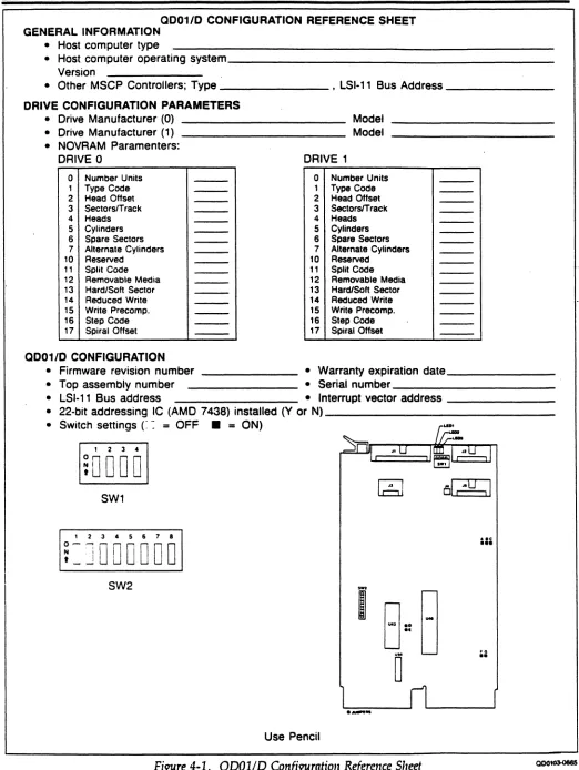
QD01/D Configuration Reference Sheet ..••.•.•..•••...••••••.•.••.•••••..•...•..••.•.... Switch Setting Example .••••••...•.•..•.••.•...•....•.•.••..•.••••...•.•...••••...•.•...•. QDOl/D Disk Controller Assembly .•...•••.••..•..•.•.•...•...•••.•....••.•...
I>ri\7e C:Cl)'liI\~ ... .
Fault Isolation Chart .•••...•.•..•••••.•••••••....•..••••.•..•.•..•.•.•.•...•.•••.•••.•...••...
QD01/D Bl~ Dia~am .•.•..•.••••••••...•.•...•.•...•.••••••..•...•...•...•....••...
Control Pin/Signal Assignments at ST-506 Disk Drive Interface (Connector 11) ... Data Pin/Signal Assignments at ST-506 Disk Drive Interface (Connector 12 or 15)
Status and Control Interface ...•...••...•...•...
viii Table of Contents
1-3 1-4
2-4
3-2 3-3 3-19
3-20
4-2 4-3 .. 4-5 4-16
5-3
7-2
8-4
8-5
(
Table 1-1 1-2 2-1 2-2 2-3 2-4 3-1 3-2 4-1 4-2 4-3 4-4 4-5 4-6 4-7 4-8 4-9 4-10 5-1 5-2 5-3 5-4 6-1 8-1 8-2 A-1 A-2 A-3 A-4 C-1LIST OF TABLES
Title
Basic Contents ..•....•...•••...•...•...••.•.••••...••••.••••••.•.•...•....•••
(2[)()1/I> ()I'tiocus ...•...•... ~ ...•...•...•...•...••••.•..•.•.•••••...•...•...••
(2001/0 General Specifications ...•.•.•.••••..••.••.•.•...••••.•••.••.•.••.••.•••••.•...••••
(2D01/D Environmental Specifications .••••...•••••.•..•.••••••••••••.••••••••.••••.•.•••• (2D01/0 Physical Specifications .••..••...•.••.•••••.•...•.••..•••••.•••••••.•..••••.••..•••.
(2D01/D Electrical Specifications ...••.•...•..••••..••.•.•..••..•.•.••••.•.•••.••..•••....•••
Subsystem Configu.ration Example ...••...•..•...•..•...•...
Device Names ...•...•...•...
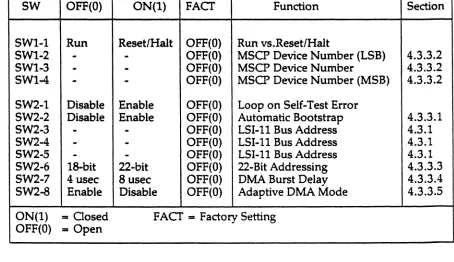
(2001/0 Switch Definitions and Factory Configu.ration .•••••.••••.••••.•..••.•...•..••• (2001/0 Jumper Definitions and Factory Configu.ration ••.••.•.••.••••..••••...•.•.•.•.. Controller Address Switch Settings ....•...•.•....•..••.•..•••••....••••.•...•...
Bootstrap MSCP Device Number ....•••••...••...•••.•••.•...•..•.••...•...•..• MSCP Device Number for the First Drive Supported by
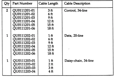
a (2 D01/D at an Alternate Address ...••...••.•..••.•...•.•.•...•••...•.•...•• (2001/0 Internal Cabling Kit (PIN (2001/013001) ....•.••••.•..•.••.•.•..•..••...••
Interface and Cable Components .••••••••..••...••...•...•••••.•.•.•..••••.••••....•...•••
IvIic:rCl"J\)( ()ffsets .•••••.•••••••••.••.••••••••••••••••••••••••••••••••••••••••••••••••••••••••••••
~SI-l1 ()ffsets .•...••••••..•••••••••••••••••••••••••••••••••••.•••••••••••••••••••••••.•••••.•..•
Configu.ration Bit Values in Decimal
Flow Otart Symbol Definitions •••••••••••••••••••••••••••••••••••••••••••••••••••.••••••.•••••
~l) ~rror <:()cies ....•...•...••.•....••...••...•.••..•.••••.••••.•.•.•.••...•.•••
MSCP Fatal Error Codes Used by the (2001/D ••••••••.••.••••••••••••.••..••.••..••.••.•• Fatal Error Codes ...•.•.•.•.•••...••.••...••.••...••••.••..••••••••.•.•..••••..••.••...•..••
(2D01/D and SA Registers ...•.••..•.•....•..•...•.•..•.••••••.••••••••.•.••••...•.•....••
LSI-11 Bus Interface Pin Assignments ..•...•.•...•.••..•••...•.•...•..•.••..••.•...•. Control and Status Interface Pin Function Description ...•...•..••.•..•.•...
SYSGEN Device Table
Priority Ranking for Floating Vector Addresses ...•.•.•.•.•....•...••...•...
CSR and Vector Address Example .•...•.•...•...•.•.•.•..•...•... Floating CSR Address Assignment Example
Drive Configuration Parameter Values ...•...•...•..•...
Page 1-3 1-4 2-1 2-3 2-3 2-4 3-6 3-8 4-6 4-7 4':'7 4-9 4-10 4-15 4-16 4-21 4-21 4-28 5-2 5-4 5-5 5-6 6-4 8-2 8-6
A-2 ~ A-4
A-6 A-7
C-2
(
EMULEX PRODUcr WARRANTY
CONTROLLER WARRANTY: Emulex warrants for a period of twelve (12) months from the date of shipment that each Emulex controller product supplied shall be free from defects in material and workmanship.
CABLE WARRANTY: All Emulex provided cables are warranted for ninety (90) days from the time of shipment.
The above warranties shall not apply to expendable components such as fuses, bulbs, and the like, nor to connectors, adaptors, and other items not a part of the basic product. Emulex shall have no obligation to make repairs or to cause replacement required through normal wear and tear or necessitated in whole or in part by catastrophe, fault or negligence of the user, improper or unauthorized use of the product, or use of the product is such a manner for which it was not designed, or by causes external to the product, such as but not limited to, power failure or air conditioning. Emulex's sole obligation hereunder shall be to repair or replace any defective product, and, unless otherwise stated, pay return transportation cost for such replacement.
Purchaser shall provide labor for removal of the defective product, shipping charges for return to Emulex and installation of its replacement. THE EXPRESSED WARRANTIES SET FORTH IN THIS AGREEMENT ARE IN LIEU OF ALL OTHER WARRANTIES, EXPRESSED OR IMPLIED,
INCLUDING WITHOUT LIMITATION, ANY WARRANTIES OF MERCHANTABILITY OR FITNESS FOR A PARTICULAR PURPOSE, AND ALL OTHER WARRANTIES ARE HEREBY DISCLAIMED AND EXCLUDED BY EMULIDC THE STATED EXPRESS WARRANTIES ARE IN LIEU OF ALL OBUGATIONS OR LIABILITIES ON THE PART OF EMULEX FOR DAMAGES,
INCLUDING BUT NOT LIMITED TO SPECIAL, INDIRECT, OR CONSEQUENTIAL DAMAGES \
ARISING OUT OF, OR IN CONNECTION WITH THE USE OR PERFORMANCE OF THE ',_ .
PRODUCT.
RETURNED MATERIAL: Warranty claims must be received by Emulex within the applicable warranty period. A replaced product, or part thereof, shall become the property of Emulex and shall be returned to Emulex at
Purchaser's expense. All returned material must be accompanied by a RETURN MATERIALS AUTHORIZATION (RMA) number assigned by Emulex.
1.1
(
{
Overview
Section
11
INTRODUCTION
The QD01/D Disk Controller, designed and manufactured by Emulex
Corporation, is a Mass Storage Control Protocol (MSCP) compatible controller with an ST-S06 peripheral interface. This manual is designed to help you install and use your QD01/D Disk Controller. It assumes that you have some
knowledge of hardware configuration, LSI-11 architecture and terminology, and interpretations of error messages and device register contents. The contents of the eight sections and three appendices are described as follows:
• Section 1 (General Description): This section contains an overview of the QD01/D Disk Controller.
• Section 2 (Controller Specification): This section contains the specification for the QD01/D Disk Controller.
• Section 3 (Planning the Installation): This section contains the information necessary to plan your installation, including MSCP subsystem and operating system considerations.
• Section 4 (Installation): This section contains the information needed to set up and physically install the controller, including switch settings and cabling. It also describes the firmware-resident diagnostics and contains instructions for loading drive configuration parameters into the
NOVRAM.
• Section 5 <Troubleshooting): This section describes fault isolation procedures that can be used to pinpoint trouble spots.
• Section 6 (Registers and Programming): This section describes the QD01/D's LSI-11 bus registers and presents an overview of the Mass Storage Control Protocol (MSCP).
• Section 7 (Functional Description): This section describes the controller architecture.
• Section 8 (Interfaces): This section describes the controller, LSI-11 bus and ST -506 interfaces.
• Appendix A (Autoconfigure): This appendix describes the DEC algorithm for the assignment of CSR addresses and vector addresses.
• Appendix B (PROM Removal and Replacement): This appendix
contains instructions to remove and replace the firmware so that th~ user can upgrade the QDOl/D Disk Controller in the field.
(
Physical Organization Overview
• Appendix C (Disk Drive Configuration Parameters): This appendix
r-contains configuration parameters for supported ST-506 disk drives. /-~
1.2
Subsystem Overview
The QD01/D Disk Controller connects high-capacity mass storage peripherals to the LSI-l1 bus on computers manufactured by Digital Equipment Corporation (DEC). The QD01/D implements DEC's Mass Storage Control Protocol (MSCP) to provide a software-transparent interface for the host DEC computer. To provide traditional Emulex flexibility in peripheral selection, the QD01/D uses the industry standard ST -506 interface as its peripheral interface. The ST -506
interface is used on 5.25-inch Winchester disk drives built by numerous manufacturers.
1.2.1 Mass Storage Control Protocol (MSCP)
MSCP is a software interface designed to lower the host computer's mass storage overhead by offloading much of the work associated with file
management into an intelligent mass storage subsystem. In concert with ST -506 compatible peripherals, the QDOl/D provides just such a subsystem. The
QDOl/D relieves the host CPU of many file maintenance tasks. The QDOl/D Disk Controller performs these MSCP functions: error checking and correction, bad block replacement, seek optimization, command prioritizing and ordering, and data mapping.
This last feature is, perhaps, the most important. This feature allows the host computer's operating system software to store data in logical blocks that are identified by simple logical block numbers (LBNs). Thus, the host does not need to have detailed knowledge of the peripheral's geometry (cylinders, tracks, sectors, etc.). This feature also makes autoconfiguration a simple matter. During system start-up, the host operating system queries the subsystem to find its capacity (the number of logical blocks that the subsystem can store).
Because the host operating system does not need to have detailed knowledge of its mass storage subsystem, the complexity of the operating system itself has been reduced. This reduction comes about because only one or two software modules are required to allow many different subsystems to be connected to a host.
1.3
Physical Organization Overview
1-2 ["troduction
The QD01/D Disk Controller is a modular, microprocessor-based disk controller that connects directly to the host computer's LSI-ll bus backplane. The
microprocessor architecture ensures excellent reliability and compactness.
"--, - !.
-Subsystem Models
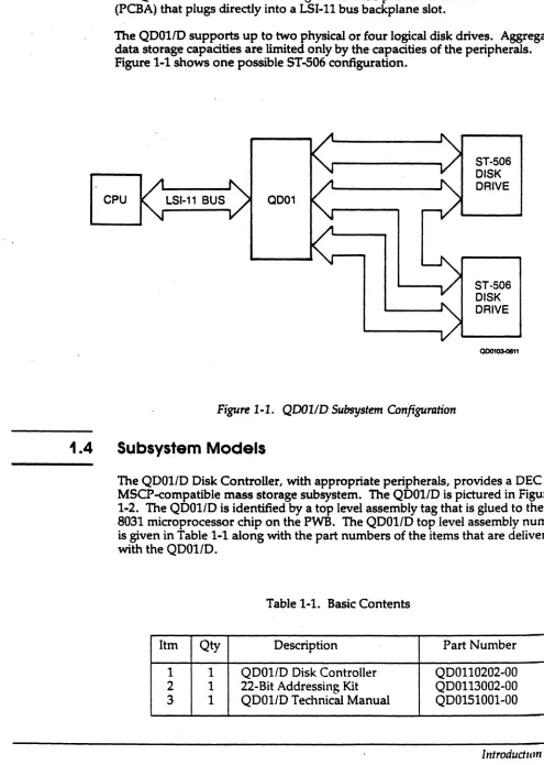
The QD01/D is contained on a single dual-wide printed circuit board assembly
(PCBA) that plugs directly into a LSI-ll bus backplane slot.
The QD011D supports up to two physical or four logical disk drives. Aggregate
data storage capacities are limited only by the- capacities of the peripherals. Figure 1-1 shows one possible ST-506 configuration.
CPU LSI-11 BUS OD01
ST-506 DISK DRIVE
ST-506 DISK DRIVE
QD01QS.0811
Figure 1-1. QDOlfD Subsystem Configuration
1.4
Subsystem Models
The QD01/D Disk Controller, with appropriate peripherals, provides a DEC
MSCP-compatible mass storage subsystem. The QD01/D is pictured in Figure
1-2. The QD01/D is identified by a top level assembly tag that is glued to the 8031 microprocessor chip on the PWB. The QD01/D top level assembly number
[image:12.612.61.556.80.775.2]is given in Table 1-1 along with the part numbers of the items that are delivered with the QD01/D.
Table 1-1. Basic Contents
Itm Qty Description Part Number
1 1 QDOI/D Disk Controller QDOll0202-00
2 1 22-Bit Addressing Kit QDOl13002-00
3 1 QDOI/D Technical Manual QD0151001-00
(
Subsystem Models
[image:13.612.103.548.86.362.2]00010300868
Figure 1-2. QDOlfD Disk Controller
Table 1-2 lists the options that can be ordered to tailor your QD01/D to your particular application.
Table 1-2. Subsystem Options
Option Description
QD0113003 QD01 Cabling Kit MICRO/PDP-ll and MicroVAX I and II Tower. Includes cables, panels, and instructions.
QU0111201-0n 1 34-line, control interface cable for ST -506 disk drives. Cable length is per customer order.
QU0111201-0n 1 20-line, data interface cable for ST -506 disk drives. Cable length is per customer order.
QU0111203-0n 1 34-line, daisy-chain control interface cable for ST -506 disk drives. Cable length is per customer order.
1 See Table 4-5 for part numbers for specific cable lengths.
[image:13.612.59.584.518.738.2](
1.5
1.5.1
Features
Features
The following features enhance the usefulness of the QDOI/D Disk Controller.
Microprocessor Design
The QDOI/D design incorporates an eight-bit, high-performance CMOS microprocessor to perform all controller functions. The microprocessor approach provides a reduced component count, high reliability, easy
maintainability, and the microprogramming flexibility that allows MSCP to be implemented without expensive, dedicated hardware.
1.5.2
Firmware-Resident Diagnostics
1.5.3
The QDOI/D disk controller firmware incorporates a self-contained set of disk preparation and diagnostic utilities. These utilities are contained in QDOI/D Revision H and above firmware. Controllers with this firmware are easily identified by a tag labeled with the top assembly number QDOII0201-00E.
These utilities allow the user to communicate directly with the QDOI/D via a firmware resident terminal driver that is compatible with either CRT or hardcopy devices connected to an LSI-1I or MicroVAX console port. These firmware-resident diagnostics (F.R.D.) provide several important disk preparation functions, including the ability to:
• Configure the controller NOVRAM • Format the drive
• Test the disk surface and replace defective blocks, and • Perform reliability testing of the attached disk subsystem.
Custom Configuration Capability
An onboard NOVRAM can be programmed for two independent physical drive configurations. Using the firmware-resident utilities, you can control drive parameters such as gap size and the number of sectors per track.
,Features
1.5.4
1.5.5
1.5.6
1.5.7
(
1.5.8
1-6 Introdudion
Self-Test
,/r
The QD01/D incorporates an internal self-test routine which exercises all parts of ~
the microprocessor, the onboard memory, the LSI-11 bus interface, and the ST-506 interface. Although this test does not completely test all circuitry, successful execution indicates a very high probability that the disk controller is operational.
If the QD01/D detects an error during self-test, it leaves three light-emitting diodes (LEDs) ON and sets an error bit in the Status and Address (SA) register (base address plus two).
Error Control
The disk controller presents error-free media to the operating system by
, correcting soft errors and retrying operations without intervention by the host.
Host-Initiated Bad Block Replacement
The QD01/D uses DEC-compatible host initiated bad block replacement to dynamically replace any defective blocks that occur during the life of the system. For maximum reliability, the QD01/D reports even corrected single bit errors as candidates for replacement.
Seek Optimization
The QD01/D is able to pool the various seeks that need to be performed and determine the most efficient order in which to do them. This is an especially important feature in heavily loaded systems. The disk controller's ability to arrange seeks in the optimum order saves a great deal of time and makes the entire system more efficient.
Command Buffer
The QD01/D contains a buffer that is able to store 13 MSCP commands. This large buffer allows the subsystem to achieve a higher throughput and to operate
i(
1.5.9
1.5.10
1.5.11
Compatibility
Adaptive DMA
During each DMA data transfer burst, the QD01/D monitors the LSI-11 bus for other pending DMA requests and suspends its own DMA activity to permit other DMA transfers to occur. The host processor programs the DMA burst length during the MSCP initialization sequence or the QD01/D defaults to 16 words per burst. Because of these adaptive DMA techniques, the QD01/D ensures that CPU functions, including interrupt servicing, are not locked out for excessive periods of time by high-speed disk transfers. The QD01/D firmware design includes a DMA burst delay of either 4 or 8 microseconds to avoid data-late conditions.
In addition, the QD01/D allows you to modify its DMA operations by disabling the adaptive DMA and defaulting to burst transfers of 8 words or less.
Block-Mode DMA
The QD01/D supports block-mode DMA for accessing memory. In this mode, the initial address of the data is transmitted, followed by a burst of up to 16 words of data. The memory address is automatically incremented to
accommodate this burst. Block mode transfers considerably reduce the overhead associated with DMA operations.
22-Blt Addressing
The QD01/D supports the 22-bit addressing capability of the extended LSI-ll bus.
1.6
Compatibility
This subsection describes the compatibility of operating systems and hardware.
1.6.1 Operating Systems
The QD01/D implements MSCP. Emulex supports its implementation of MSCP beginning with the indicated version of the following DEC operating systems:
Operating System
Micro/VMS RSTS/E RSX-llM
RSX-llM-PLUS
RT-ll
Ultrix-ll Ultrix-32
Version
4.0 8.0 4.1
2.1
5.1 3.0
1.1
Compatibility
1.6.2
1-8 Introdudion
Hardware
The QD01/D Disk Controller complies with DEC LSI-ll bus protocol, and it '''-~
directly supports 22-bit addressing and block-mode DMA. The QD01/D also supports scatter-write and gather-read operations on the Micro VAX I.
The disk drives supported by the QDOl/D are not media compatible with comparable DEC MSCP products; however, this is not a problem due to the fixed nature of most DEC drives.
ST -506 disk drives that are supported by the QD011D should provide buffered head stepping. Buffered stepping is required to provide adequate performance
(-2.1
Overview
Section
21
CONTROLLER SPECIFICATION
This section contains the general, environmental, physical, electrical, and port specifications for the QD01/D Disk Controller.
Subsection
1.2 1.3 1.4
1.5
Title
General Specification
Environmental Specification Physical Specification
Electrical Specification
[image:18.612.42.573.28.751.2]2.2
General Specification
[image:18.612.92.566.386.722.2]Table 2-1 contains a general specification for the QD01/D Disk Controller.
Table 2-1. QD01/D General Specifications
Parameter Description
FUNCrION Providing mass data storage to Digital Equipment Corporation (DEC)
computers that use the LSI-ll bus
Logical CPU Interface Emulates DEC's Mass Storage Control Protocol (MSCP)
Diagnostics Embedded diagnostics
Operating System MicrolVMS V4.0 and above
Compatibility RSTE/S VB.O and above
RSX-llM V4.1 and above
RSX-llMPLUS V2.1 and above
RT-ll VS.l and above
Ultrix-ll V3.0 and above
Ultrix-32 V1.1 and above
CPU 1/0 Technique Direct Memory Access (DMA), including adaptive techniques and block mode; supports scatter-write and gather-read operations on the MicroVAXI
(continued on next page)
(
[image:19.612.81.585.65.658.2]General Specification
Table 2-1. QD01/D General Specifications (continued)
Parameter Description
INTERFACE
CPU Interface Extended LSI-11 bus interface
Device Base Address
Standard 177721508
Alternates 177721548
177603348 177603408 177603448 177603508 177603548 177603608
Vector Address Programmable
Priority Level BR4
Bus Loading 1 dc load, 2.5 ac loads
Peripheral Interface Seagate Technology (ST-S06)
Number of Physical 2 Disk Drives Supported
Interface Cables 34-line control cable (daisy-chain), maximum 20 ft (3 m)
20-line data cables (radial), maximum 20 ft (3 m)
Step Pulse Interval Programmable, 3msec to 12 usec1
Firmware Diagnostic Host Console
LSI-ll DL V11J or Processor-resident console
interface
.
MicroVAX Processor-resident console port
1 For adequate performance under DEC operating systems, Emulex recommends using a disk drive that can buffer step pulses.
2·2 Controller Specification
/" "",-,-'
--" .
/
Physical Specification
2.3
Environmental Specification
2.4
Table 2-2 contains the environmental specifications for the QDOI/D Disk
Controller.
Table 2-2. QDOI/D Environmental Specifications
Parameter . Description
OPERATING 10°C (SOOF) to 40°C (104°F), where maximum
TEMPERATURE temperature is reduced 1.8°C per 1000 meters (1°F per 1000 feet) altitude
RELATIVE HUMIDITY 10% to 90% with a maximum wet bulb of 28°C (82°F) and a minimum dewpoint of 2°C (3.6°F)
COOLING 6 cubic feet per minute
-HEAT DISSIPATION 82 BTIJ per hour
Physical Specification
Table 2-3 contains the physical specifications for the QDOI/D Disk Controller.
Table 2-3. QDOI/D Physical Specifications
Parameter Description
PACKAGING Single, dual-wide, four-layer PCBA
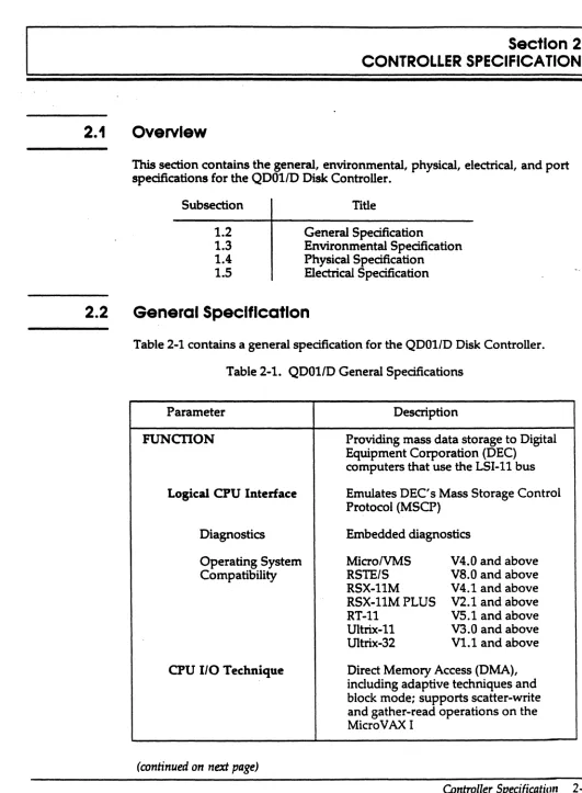
Dimensions 5.186 by 8.70 inches
13.172 by 22.09 centimeters (see Figure 2-1)
Shipping Weight 3 pounds
(
Electriclll Specification
2.5
Electrical Specification
Table 2-4 lists and describes the electrical specification for the QD011D Disk
[image:21.612.114.548.116.706.2]Controller. .
Table 2-4. QDOl/D Electrical Specification
Parameter Description
POWER 5 Vdc.±. 5%, 2.6 amperes (A)
5.1111NCH1S
I
(13.172 - t
I~
~I
III
r-J
Figure 2·1. QDOlID Disk Controller Dimensions
1.700 I NCHES
eml (22.DtI
QD01034134
2·4 Controller Specification
3.1
3.2
Overview
Section
31
PLANNING THE INSTALLATION
This section is designed to help you plan the installation of your QD01/D Disk Controller. Taking a few minutes and planning the configuration of your subsystem before beginning its installation should result in a smoother installation with less system down time. This section contains QD01/D
application examples and configuration procedures. The subsections are listed in the following table:
Subsection
3.2
3.3
3.4
3.5
Title
MSCP Subsystem Configuration A DEC MSCP Subsystem
The QD01/D MSCP Subsystem Operating Systems, Device and
Vector Addresses
MSCP Subsystem Configuration
The following paragraphs describe MSCP Subsystem concepts, including architecture, unit numbering, capadties, and related concepts.
3.2.1
Architecture
MSCP is a protocol designed by pEe for mass storage subsystems using Digital Storage Architecture (DSA). In a MSCP mass storage subsystem, DSA
comprises three functional and physical layers:
• Host Layer. An MSCP class-driver in the host system receives requests from the operating system and then relays data and commands to the controller in MSCP message packets.
• Controller Layer. The MSCP controller communicates with both the host layer and the mass storage layer. The controller transmits MSCP message packets to and from the host MSCP class-driver and performs data-handling functions for the mass storage devices. The QDOl/D functions as the controller layer.
• Mass Storage Layer. The mass storage peripheral devices communicate with the MSCP controller and send or receive data as spedfied by the MSCP controller.
(
A DEC MSCP Subsystem
. 3.2.2
3.2.3
MSCP defines the form of the message packets that are exchanged by the host and the MSCP controller. The QD01/D implements MSCP in mass storage subsystems using ST -506 as the peripheral interface .
Peripheral Numbering
Each MSCP peripheral on the system is identified to the operating system by an MSCP device name. An MSCP device name consists of a device class identifier and a unit number. The device class is indicated by a two-letter prefix; MSCP disk devices are indicated by the prefix DU.
With the exception of Micro VMS systems, DEC operating systems require that
all MSCP peripherals on a system have differentMSCP device numbers, even if
. they are managed by separate MSCP controllers at separate LSI-11 bus device addresses. For example, under RSX-llM-PLUS, if there are three peripherals on the first MSCP controller (at 772150tJ), then the first peripheral on the second MSCP controller (in floating CSR address space) is numbered DU3.
Peripheral Capacities
The capacity of peripherals in an MSCP subsystem is measured in logical blocks. Each logical block contains 512 bytes of data. The MSCP controller can report the capacity of a peripheral to the operating system. A 10M byte peripheral such as DEC's RDS1 is able to store about 20,000 logical blocks.
3.3
A DEC MSCP Subsystem
Figure 3-1 shows the organization of a typical DEC MSCP subsystem for the LSI-11 bus. The MSCP host and controller functions are combined in a single piece of hardware, in this example the DEC RQDXl. The RQDX1 supports RD51, RD52, or RDS3 hard disk drives and the RXSO S.25-inch floppy drive. The RQDX1 plugs directly into the LSI-ll bus and is attached to disk drives via a disk-drive-native interface.
CPU LSI·11 DRIVE DUO
DRIVE
DU1
DRIVE
DU2
0D01CJ3.1578
Figure 3-1. DEC MSCP Subsystem Logical and Pltysical Configuration
.(
((
3.4
The QDOl/D Subsystem
[image:24.612.138.535.191.410.2]The Q001/0 Subsystem
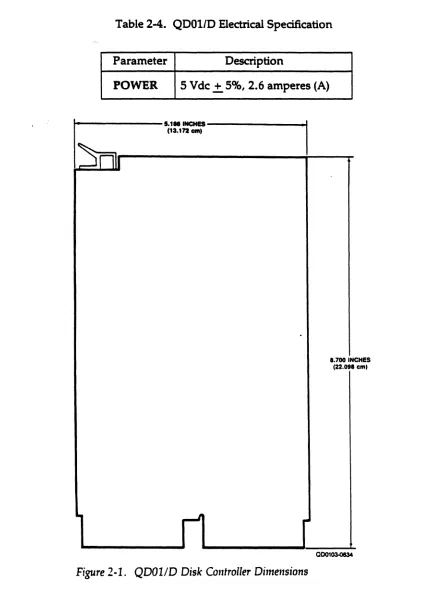
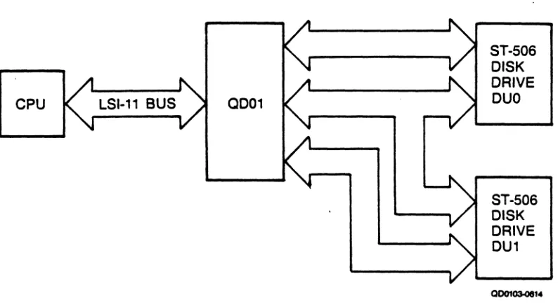
Figure 3-2 illustrates a typicalQD01/D MSCP subsystem. As with the DEC implementation, the QD01/D is connected directly to the LSI-ll bus. The QD01/D, however, uses the ST-506 peripheral interface to communicate with one or two disk drives.
CPU LSI-11 BUS 0001
ST-506 DISK DRIVE DUO
ST-506 DISK DRIVE DU1
Figure 3-2. QD01/D Subsystem Logical and Physical Configuration
The MSCP subsystem provided by the QDOl/D is essentially analogous to the DEC MSCP subsystem. As in the DEC subsystem, the QDOl/D MSCP controller connects directly to the LSI-ll bus. As an MSCP controller, the QDOl/D receives requests from • the host, optimizes the requests, generates ST -506 commands to perform the
operations, transfers data to and from the host, transfers data to and from the device, and buffers data as necessary. When the command is complete, the controller sends a response to the host.
The QDOl/D also performs all of the functions of the peripheral controller, including serialization and deserialization of data. The QD01/D connects to the peripherals it supports via the ST-506 interface.
(
The QD01lD Subsystem
3.4.1
Example 3-1:
3.4.2
3.4.2.1
Logical Unit Numbers
As noted in section 3.2.2, most DEC operating systems do not allow any MSCP disk devices on one system to have the same unit number, even though they may be controlled by separate MSCP'controllers at different base addresses.
DEC MSCP-type drives can accept unit identification plugs that define addresses from 0 to 255. Disk drives controlled by the QD01/D do not have this flexibility; the QD01/D can detect only two unique drive addresses at its ST -506 interface: 0 and 1. To prevent a unit-number conflict between the QD01/D's drives and another MSCP controller's drives, the QD01/D employs switches to change the drive logical unit number that is reported to the operating system.
An MSCP controller
at
a standard base address supports four disk drives; a QDOlID atan alternate base address supports
two
disk drives. An offset of 4 is specified for theQDOlID. This causes the QDOlID disk with address 0 to be reported to the operating
system as logical unit number (LUN) 4. The QDOlID disk 1 is reported as LUN S.
The offset for the logical unit number is specified by using switches SWl-2 through SWl-4 on the QD01/D.
Q001/D Subsystem Logical Configuration
This subsection explains the algorithm used by the QDOl/D to map logical MSCP peripherals onto the physical disk drives provided by the QD01/D subsystem.
Logical Devices
The phrase "logical MSCP disk drive" refers to the disk drive as it appears to the operating system. That is, the operating system associates a disk drive of known type (in this case, an MSCP disk drive) with a unit number and a capacity. The QD01/D MSCP controller presents that information to the operating system aiter initialization on command.
Because the MSCP controller is responsible for establishing the relationship between unit number and capacity, it is possible for the controller to divide its physical disk drives into more than one logical unit. For example, if a physical disk drive has a capacity of 234,090 blocks, the MSCP controller can divide that capacity into unequal parts: for example, 208,080 blocks and 26,010 blocks. Each part is then assigned a separate unit number, and the unit number and capacity of each part is presented to the operating system.
The operating system then sees the two parts as separate disk drives, even though the data is actually stored on the same physical drive. The two parts are called logical disk drives, and the numbers that identify them are called MSCP unit numbers.
3·4 Planning the Installation
/-(""'
"
~'
, / -- ~,
( j
The QDOllD Subsystem
A drive configuration that supports multiple logical units is specified by the data . that is stored in the configuration Nonvolatile Random Access Memory
(NOVRAM). Information for programming the configuration NOVRAM is given in subsections (4.7, 4.8, and 4.9). The field that causes a drive to be divided into multiple logical units is called the Split Code. There are four types of split codes: no split, cylinder split, head split, and reverse head split:
• When no split is specified, the entire physical drive is one logical drive.
• Cylinder split codes divide a physical drive by cylinders. A Starting Cylinder Offset field in the NOVRAM specifies the first cylinder of the second logical drive. Alternate cylinders are divided evenly between drives. For example, if the physical drive has 645 cylinders and is split
50/50, the first 322 cylinders are assigned to one drive and the second 322
cylinders are assigned to the other (the odd cylinder is not used).
• Head split codes divide the drive by data heads. A Starting Head Offset field in the NOVRAM specifies the first head of the second logical drive. When the drive is split by data heads, each logical drive has its own platter(s)i consequently, the lower blocks of one logical drive are in the same physical cylinder as the lower blocks of the other logical drive. For example, a Maxtor drive with 15 heads might be divided so that the first logical unit is assigned heads 0 through 6, and the second logical unit is assigned heads 7 through 14. The Starting Head Offset has a value of7.
• Reverse head split codes also divide the drive by data heads, but assign the lower numbered heads to drive 1 and the higher numbered heads to drive O. If you entered a reverse split code for the previous Maxtor 4380 example, the first logical unit is assigned heads 8 through 14 and the second logical unit is assigned heads 0 through 7. The Starting Head Offset has a value of 8.
The head splitting technique has a performance advantage over the cylinder method. Typically, most disk accesses are made in the lower cylinders of a disk because many system-oriented files are located there, including the drive's directory. Because the low (and high) cylinders are vertically aligned between the two logical drives when the head splitting technique is used, switching between head-split logical drives requires less • head movement than switching between cylinder-split drives.
(
The QDOllD Subsystem
3.4.2.2
Device NumbersThe drives supported by the QD01/D are assigned MSCP device names by the ~
. operating system. As described in subsection 3.2.2, an MSCP device name consists of a device class prefix and a device unit number. Drives are assigned MSCP device numbers beginning with zero (0). The conventions for numbering multiple MSCP drives vary by operating system.
Under RSX-11M, RSX-11M-PLUS and RT-11, DUO is assigned to the first drive on the first MSCP controller, where "first" means the controller located at the standard base address. Unit number 1 would be the second drive on the first controller, etc. H there are two MSCP controllers on the system, the units installed on the second begin numbering at n + 1, where n equals the highest unit number of the first MSCP controller.
RSTS/E requires that drives supported by a standard MSCP controller be
numbered starting at 0 and drives supported by an alternate MSCP controller be numbered starting at 4.
Because MSCP device names under Micro VMS designate the supporting MSCP controller, the unit numbering is less restricted. For example, two drives which are supported by a standard MSCP controller might be DUAO and DUAl and a third drive supported by an alternate MSCP controller might be DUBO.
Table 3-1 is an MSCP unit numbering example under the RSX-11M operating system which shows the MSCP number versus the actual physical addresses assigned to all the components. The physical disk drive (unit number 1) of the
second controller is split into two logical units. Note that two device names are ,,/ associated with that drive.
Table 3-1. Subsystem Configuration Example
Drive
QD01/D Unit Device
Address Device Description Number Name
772150 Atasi 3046 0 DUO
Atasi 3046 1 DU1
760334 Maxtor XT1140 0 DU2
(Floating) (head split) DU3
Maxtor XTl140 1 DU4
NOTE
All MSCP peripherals supported by the QD01/D use the same device identifier - RD51.
3.5
Operating Systems, DeTJ;ce and Vector Addresses
Operating Systems, Device and Vector Addresses
Before the installation of any peripheral device can be considered complete, the computer's operating system must be made aware of the new resource. The information provided in this section is intended to supplement your DEC operating system resources and to be used as an aid in planning the installation of your QD01/D.
An operating system can be made aware of a new resource in three ways:
• The operating system can poll the computer's 110 device address space.
• The device can be manually connected using CONNECT or CONFIGURE statements.
• The user can tell the operating system about a device during an interactive SYSGEN procedure.
The first technique is referred to as autoconfigure, and it is essentially automatic. The second technique requires that CONNECT statements be placed in a special command file that is executed each time the computer is bootstrapped. The third technique, interactive SYSGEN, creates a configuration rue that the operating system references when the system is bootstrapped. All techniques accomplish the same result: they associate a specific device type with a bus address and interrupt vector.
Most recent versions of DEC operating systems use autoconfigure to some extent, and try to follow the same rules. The RTI1 operating system does not use autoconfigure, but can locate devices that reside at a standard address. There are some differences among operating systems, however, especially with regard to MSCP controllers at alternate LSI-ll bus addresses. The following paragraphs address these differences for each supported operating system. This discussion includes information on choosing appropriate LSI-ll bus device addresses and interrupt vectors for the subsystem.
The following operating system discussions give procedures for choosing LSI-ll bus addresses for the first MSCP controller and any subsequent controllers in the host configuration. No instructions are provided for programming the chosen address into the QD01/D.
MSCP-type controllers contain two registers that are visible to the LSI-ll bus 110
page. They are the Initialization and Polling (IP) register (base address) and the Status and Address (SA) register (base address plus 2). The IP register, th~ CSR address, LSI-11 bus address and the base address all refer to the same register. All of the operating systems described in the following subsections use the standard LSI-11 bus address of 17721508 for the first controller on the host system.
Operating Systems, DetJice and Vector Addresses
Vector addresses for MSCP controllers are not selected by using switches on the
controller, but are programmed into the controller during the Initialization
(--~
process. Many operating systems select the vector address automatically. If an ',--/ . . operating system requires manual input of the vector, the procedure notes that. fact.
Again, although DEC has attempted to standardize treatment of peripherals by operating systems, some differences do exist. Table 3-2 lists and describes the device names assigned to MSCP devices under five operating systems. Two controller names and two drive names are given to indicate the numbering scheme.
Table 3-2. Device Names
Operating System Controller Drives Supported First, Second by First Controller
RSTS/E RUO, RUl DUO,DUl
RSX-llM
--
DUO,DUlRSX-llMPLUS DUA, DUB DUO,DUl
RT-ll PortO, Portl DUO,DUl
MicroVMS PUA, PUB DUAO, DUAl
Ultrix-ll udaO,udal raO, ral
Ultrix-32m udaO, udal raO, ral
The information regarding operating systems in these subsections is subject to change. The following discussions are based on three assumptions:
• This is the first pass that is being made through SYSGEN; therefore, no saved answer file exists. Answer N (no) to questions such as "Use as input saved answer file? If
• Your host system configuration conforms to the standard LSI-ll device configuration algorithm (otherwise autoconfigure results are not reliable).
• You are generating a mapped version of the operating system on the appropriate hardware (unless you are using RTll).
3.5.1 RSTS/E Operating Systems (V8.0 and above)
RSTS/E scans the hardware to determine configuration each time the system is bootstrapped. The scanning program is called INIT.SYS and it relies on the same hardware configuration conventions as do the other DEC operating systems.
The RSTS/E operating system can support two MSCP controllers. The first MSCP controller must be located at the standard LSI-ll bus address, 772150!'l. According to DEC documentation, the second unit should be located in floating address space. Fot' an alternate QDOI/D, Emulex suggests specifying a LSI-I t bus address of 76033411 llsing the HARDWARE option of the INIT .SYS program.
3.5.1.1
3.5.2
3.5.2.1
Operating Systems, Device and Vector Addresses
The INIT. SYS program uses a user-specified table, located in the currently installed monitor, to make exceptions to the autoconfigure algorithm. This table
is modified by the HARDWARE option of the INIT .SYS program. Use of this table allows an MSCP controller to be placed at virtually any address on the I/O page. Note that this table must be reset any time a new monitor is installed. Emulex suggests using an LSI-11 bus address of 7603348 for an alternate QD01/D. An MSCP controller must be located at the standard address to be a bootstrap device.
Interrupt vector addresses are assigned to the MSCP controllers by INIT.SYS and programmed into the devices during initialization.
Adding MSCP Support
Support for an MSCP controller must be included in a monitor at SYSGEN time. To include support for an MSCP controller in a RSTS/E monitor, respond to the SYSGEN question "number of MSCP controllers" with the number of MSCP controllers on the system.
Units connected to MSCP controllers will be accessible to an online RSTS/E system only after the monitor is successfully SYSGENed and installed with the INSTALL suboption of the INIT.SYS program, and the units have been
successfully initialized with the DSKINT suboption of lNIT.SYS.
Operating Systems (V5.1 and above)
The RT-11 Operating System supports up to four MSCP controllers with up to 256 devices (total) on the four controllers. The following paragraphs discuss the LSI-11 bus and vector addresses for MSCP controllers under RT-11 in host systems with only one MSCP controller and in those with more than one controller. Disk partitioning, a unique feature of RT -11 that is applicable regardless of the number of controllers, is also discussed.
Installing a Single MSCP Controller
If your host system includes only one MSCP controller, install it with a LSI-ll bus address of 772150s. RT-ll will find and install the handler (driver) for that controller. In single MSCP controller configurations, it is not necessary to run SYSGEN. You may use one of the pregenerated monitors that are provided with the RT-11 Distribution. Emulex recommends that you modify the system startup command file, STARTx.COM, to properly partition the disk drives. See
subsection 3.5.2.3.
Operating Systems, De71ice and Vector Addresses
3.5.2.2
Installing Multiple MSCP ControllersJfyour host system includes more than one MSCP controller, you may either modify the MSCP handler as described in the RT-11 Software Support Manual or perform a SYSGEN. The following procedure describes the SYSGEN technique (user input is in boldface print):
1. Initiate SYSGEN:
lim SYSGBN<retum>
Answer the next group of questions appropriately.
2. Indicate that you want the system to use the startup command file when booting:
3.
Do you want the startup indirect file (Y)? Y<retum>
The startup command file is required to allow additional MSCP
controller LSI-11 bus addresses to be specified and to partition the disks consistently when the system is bootstrapped. Answer the next set of questions appropriately.
Indicate that you want MSCP support when the Disk Options question appears:
Enter the device name you want support for [dd]: DU<retum>
4. Indicate the number of MSCP controllers on your system in response to
this question:
Bow many ports are to be supported (1)? 2<retum>
RT-11 refers to individual MSCP controllers or controllers as ports. Each port has its own LSI-ll bus and vector addresses.
5. Specify support for all other devices in your host system configuration as well. Indicate that there are no more devices by entering a period:
Enter the device name you want support for [dd]: .<return>
3·10 Planning tI,e Installation