Design Report
Reduction of support structures
Rev. Author Date Description Checked Approved
A A.T.L. Reimert
07-23-2014 Final Report
B A.T.L. Reimert
14-08-2014 Final Report
Comments:
Summary
Huisman is a privately owned company operating globally with extensive experience in the design and manufacturing of heavy construction equipment for world’s leading on- and offshore companies. The facility in Fujian Province (Xiamen area) in China is one of the production facilities of Huisman. The production facility has been fully operational since April 2007 and delivers a significant contribution to the overall Huisman engineering and production capacity. Huisman China (HCN) is a production facility with a total area of 284,000 m2.
Due to the opening of the first quayside owned by an international company in China in 2012 a large storage area is obtained. In combination with requests of clients to store their products passed the delivery date, the amount of products currently stored have rapidly increased. During storage additional support structures are used for support of the products. Amount of supports that are used for one product is, on average, equal to 19 percent of the own weight of the product.
The big stock of support structures, equal to 2600 metric tons, is divided into two types; workshop supports and spreader boards. Each support has its own functions and requirements. Some of the support structures are used for different functions which has as result that they are not used in the most efficient way. By evaluating the different functions of the supports the efficiency of the support with respect to weight is increased.
Spreading out the product weight over the floor and supporting the product to make sure transportation, by use of self propelled modular transport vehicles, is possible are the main functions of the supports. Investigating the current max allowable local floor pressure resulted in some remarkable findings: 1) local floor pressure is equal to the global floor pressure and 2) there are no calculations available within Huisman China about the current floor pressures. A local design institute has determined the current floor pressure according to a soil survey without providing HCN calculations.
With use of different models (according to the American Concrete Institute) the validity of the current floor pressure is examined and a max allowable local floor pressure according these models is determined. These models (based on Westergaard’s equations and footing calculations) calculate the stresses in the concrete foundation. This is done for different local loadings with keeping the properties of the soil layer, laying beneath the concrete foundation into account. According these models, the max allowable local floor pressure can be increased with a factor of four up to 20mT/m2 for the big storage yard and with a factor of 15 up to 75mT/m2 for the quayside.
With keeping different floor pressure scenarios in mind, new support structures are designed. During design different loading scenarios for the support structures are also taken into account. The new designs for the support structures result in a significant reduction of stock. The reduction is varying for the different combinations of max allowable floor pressure and loading conditions between 486mT up to 1186mT. This is equal to a reduction of 19 – 46% with respect to the total amount of stock at HCN and a reduction of 29 – 71% with respect to the stock that can be replaced by the new design.
Further investigation about the floor pressure at HCN and evaluating more design possibilities should give final outcome about the design that will lead to support structure that is most efficient with respect to weight.
Terminology & abbreviations
Term Explanation
CoG Centre of Gravity
HCN Huisman China
HLMC Heavy Lift Mast Crane
LTB Lateral Torsional Buckling
mT Metric Ton
OMC Offshore Mast Crane
PMC Pedestal Mounted Crane
PMOC Pedestal Mounted Offshore Crane
QS Quayside
SB Spreader board
SPMT Self Propelled Modular Transport
SS Support Structure
SWL Safety Working Load
SYI Storage Yard Phase I
SYIII Storage Yard Phase III
Table of content
1
Introduction ... 5
2
Current situation and problem definition ... 6
2.1 Current situation ... 6
2.1.1 Support structures ... 6
2.1.2 Floor pressure ... 8
2.1.3 Transport barges ... 9
2.2 Problem definition ... 10
3
Max allowable local floor pressure ... 11
3.1 Models ... 11
3.2 Limitations ... 12
3.3 Results... 12
3.3.1 Storage Yard Phase III ... 12
3.3.2 Quayside ... 13
4
Redesign Specifications ... 14
4.1 Changes ... 14
4.2 Remarks ... 14
4.3 Requirements ... 15
5
Redesign Concepts ... 16
5.1 Support beam ... 16
5.2 Column structure ... 17
5.3 Floor plate ... 18
6
Redesign results ... 19
6.1 Final design ... 19
6.2 Loading scenarios ... 20
6.3 Results... 22
Conclusion ... 25
Recommendations for Implementation ... 26
Recommendations for further investigation ... 27
References Report ... 28
Appendices ... 29
1
Introduction
Huisman is a privately owned company operating globally with extensive experience in the design and manufacturing of heavy construction equipment for world’s leading on- and offshore companies. With engineering and production capacity in The Netherlands, Czech Republic and China, Huisman is generating close to 100,000 m2 of total production surface. The new to build production facility, which should be operational in 2014, will increase this production surface even more. Together with the local sales, engineering and service supports in Australia, Norway, Brazil, Singapore, Slovakia and the USA a dedicated service team of skilled professionals is always able to provide advice and service support before, during and after installations and delivery.
The facility in Fujian Province (Xiamen area) in China is founded to facilitate customers in this region and to increase the overall production capacity. The production facility has been fully operational since April 2007 and delivers a significant contribution to the overall Huisman engineering and production capacity. Huisman China (HCN) is a production facility with a total area of 284,000 m2. Part of the terrain is the first quayside owned by an international company in China that is opened up in 2012. This quayside is specially constructed by Huisman to increase production area and be self-reliant for loading and unloading.
Owing to the opening of the new quayside in 2012 a large storage area is obtained. In combination with requests of clients to store their products passed the delivery date, the amount of products currently stored have rapidly increased. During production and storage of the products, additional support structures are needed which results in a big stock. This stock exists out of two types of support structure; workshop supports and spreader boards. The usage of these two types of support structures can be split up into mainly two categories; distribution of the floor pressure to ensure that the max allowable floor pressure is not exceeded and supporting of the product. The distribution of the floor pressure is in its turn divided into the floor pressure of the different areas on the site of HCN and the deck pressure on the transport barges that are sometimes used to transport the product to the customer.
The total stock of support structures results in a big amount of steel that is used for storage of products. By having a look at the validity of the current floor pressure values and by assessing the current design of the support structures it should be possible to come up with possibilities to reduce the total amount of steel needed for support structures.
The current floor pressure is based on a soil survey performed by a local design bureau. In theory it is not allowed to exceed the max allowable floor pressure determined by the design institute because of warranty reasons. The stacking units are in the current situation constructed out of separated stacking units; the spreader boards and workshop supports. For the support structures that are used to support a product it should always be possible to transport the product together with all the used support structures over the site of HCN by use of self-propelled modular transport vehicles. The dimensions and safety working load of the SPMTs results is some constraints for the support structures.
In Chapter 2 the current situation of the floor pressure distribution and the support structure use is discussed. In Chapter 3 the floor pressure at HCN is discussed into more detail. Chapter 4, 5 and 6 contain information about the design of the new support structures.
2
Current situation and problem definition
The final purpose of this report is to come up with a potential reduction of the total stock of support structures (SSs). To realize this, it is important to be aware of the current situation. Investigating the current situation shall reveal potential points of improvement, which can lead to reduction of stock. This is described in this chapter.
2.1
Current situation
HCN uses SSs for multiple purposes. The SSs are used to support the products during the production phase in the workshops and during transport to, and storage at the quay side (QS) or storage yard (SY) until delivery date. Except for support of the products are the SSs also used to distribute floor- and deck pressure during storage on the terrain of HCN and during transport on transport barges.
2.1.1
Support structures
The SSs can be split into two types of supports; spreader boards (SBs) and workshop supports (WSSs). On March 17th of 2014 the stock at HCN was counted and inventoried. Distinction is made between the different type of SSs, between the storage of SSs on different areas at the site of HCN and between the usages of the SSs. This way it is possible to divide the total stock over different categories to indicate efficiency opportunities in a later phase.
In Appendix A, a list is shown containing the entire stock at HCN and the location of the SSs on the site. From this list it can be noticed that the total stock has a weight of 2845 metric tons. 1 240mT of this stock is due to 25 meter long SBs. From this point on these SBs are not taken into account because they are only used for ‘special cases’, which is out of the scope of this project. Furthermore it can be noticed that the 830mT stored at the (QS) together with the 972mT stored at the storage yard phase III (SYIII) represent the largest part of the stock. This part of the stock is only used to store out the products at the site of HCN. For the remaining 800mT (322mT is in use in the big workshop (WS B1A) and 170mT is in use in the small workshop (WS 01&02)) it is assumed that the SSs are used in the same way as the SSs at the QS and the SYIII. From the same list it can also be noticed that WSSs represent 23 percent of the total stock while the SBs represent the remaining 77 percent.
WSSs are mainly used to bring the product to a certain height. Sometimes this height is needed to perform work on the product but it is almost always needed for transportation with self-propelled modular transport vehicles (SMPTs). The SPMTs (Drawing A08-00001-00-00A [5]) have a height clearance of 1450mm and have to drive below the product. Since the main function of the WSSs is to bring the product to a certain height and thus to support the structure, it is assumed that 100 percent of the WSSs are used for supporting purpose.
The SBs, are in contrast to the WSSs, used to fulfil two functions. First function is spreading out the floor pressure; the max allowable floor pressure has to be kept in check always. This means that when this floor pressure seems to be exceeded, SBs are placed beneath the WSSs to make sure this will not happen. For the distribution of the product load to the deck of the transport barges, the SBs are used in the same manner. Second function of the SBs is supporting the structure. The SPMTs that are used for transportation of the product result besides height clearance also in restriction of the passage width for the complete SS. Due to the width of the SPMTs the WSSs must be placed at least 6 meters away from each in order to drive in between. In order to overcome this distance, SBs are used; the SBs have supporting function.
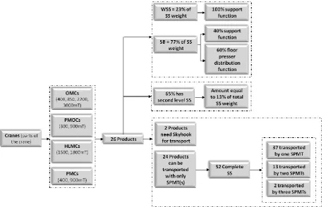
To determine the influence of the two use categories (supporting of the product and load distribution to the floor) of the SSs, the load out configuration for multiple products is examined; this results in the product range for this project. The following cranes (or a part of that crane) are evaluated: 300 and 900mT PMOCs, 400, 850, 2200 and 3000mT OMCs, 1500 and 1800mT HLMCs and 400 and 900mT PMCs. This product range covers a large area of HCNs products and is therefore assumed to be representative for the entire product range of HCN. For the (parts of the) cranes, information about the crane and information about the SSs used are listed in Appendix B. From this Appendix it can be seen that 44% of the stock is used for distribution of the floor pressure, while 56% is used to support the product. With the full support function of the workshop supports this means that almost 60 percent of the
SBs are used for distribution of the floor pressure and the remaining 40 percent is used for support of the structure. Check:
2-1 Appendix B also gives information about the amount of SSs that is on average used to support a product. This amount is equal to 19 percent of the own weight of the product. Besides this 19 percent it is found that:
In 65% of the cases, the SS support the product on a second level (Figure 2). The amount of SSs used for that second level is equal to 13% of the total stock.
Two products can’t be transported by only making use of SPMTs; they are not supported by a complete SS, see Figure 3. These products have to be lifted on the SPMTs by use of a crane (for example in the workshop). The SPMTs drive to the QS and with use of the Skyhook the product is stored at the QS.
The transportation of the remaining 24 products is done by making use of only SPMTs. In total there are 52 complete SSs used for the storage of the 24 products. Sometimes one (set of) SPMT(s) is used to transport one complete SS and sometimes it is possible that one (set of) SPMT(s) can transport two complete SS (Figure 4).
From the 52 complete SSs, 37 structures are transported by use of a single SPMT, 13 structures are transported by use of a set of two SPMTs and 2 structures are transported by use of a set of three SPMTs.
[image:7.595.84.547.329.623.2]A short overview of the results obtained by evaluating the product range is given in the figure below.
Figure 2: One complete SS with a second level support on top
Figure 3: 1800mT HLMC stored at the QS with use of the Skyhook.
Figure 4: Three complete SSs are transported by use of two singe SPMTs
2.1.2
Floor pressure
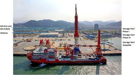
For the evaluation of the floor pressure distinction is made between the different areas at HCN. The total area of HCN is split into different areas, with all their own max allowable floor pressures. There are the two main workshops, WS B1A and WS 01&02 (10mT/m2), the storage yard phase I (SYI) (3mT/m2), the storage yard phase III (SYIII) (5mT/m2) and the quay side (QS) (again divided into several floor
pressures, storage yard at quay side is however 5mTm2). Drawing of the complete site of HCN with all max allowable floor pressures for each area can be found in drawing “A07-20280-00-10F” [6]. The site of HCN is shown in Figure 5.
Max allowable floor pressure [mT/m2]
WS B1A and WS 01&02 10
Storage yard Quayside 5
Storage yard Phase III 5
Storage yard Phase I 3
Figure 5: Site of HCN with the EMAS AMC in front of the Quayside
The different max allowable floor pressures are determined by a local design institute; “Fujian Architectural & Light Textile Design Institute”. The max allowable floor pressures are based on a soil survey. During this survey samples of the different ground layers are taken. For all the layers, different tests are performed to determine the properties of the layer. When the results are known, the max allowable floor pressure is determined.2 The tests and calculations that are necessary to determine the max allowable floor pressure are according the Chinese code “Load code for the design of building structures” [7].
In the current situation no distinction is made between local floor pressures and global floor pressure. For the QS and SYIII it is at the moment not possible to make this distinction since it is unclear how the exact value for the floor pressure is determined. For the workshops the differences between the local and global floor pressure is however already known but not implemented yet. There are drawings available which contain information about the maximum SWL for different store out configurations in the workshops. The foundation beneath the workshop is a pillar foundation; the SWL depends on the position of the local loads with respect to the piles. Drawings of the pillar foundation and plans containing the max allowable local floor pressure in the workshops are shown in Appendix C. It can be seen that local floor pressure in the big workshop starts from 40mT/m2 varying up to 200mT/m2.
The floor pressure is based on the soil survey, ‘Report for geology survey of dream hall’ [8] performed at the QS. The soil survey of the SYIII is not available. Therefore it is assumed that the soil beneath the QS and SYIII is the same. The foundation on top of the upper soil layer is not the same for the SYIII and QS. The foundation at the SYIII exists out of a detritus layer with concrete cast-in-situ structures on top. For the QS there is a detritus layer, with a lean concrete layer, a sand layer and precast concrete blocks on top. More information about the two foundations can be found in Appendix D.
At the moment it is not allowed to exceed the max allowable floor pressure at one of the sites of HCN. When this max allowable floor pressure is exceeded the design institute is no longer responsible when damage occurs and therefore the design institute will not repair the damage in the form of warranty.
2.1.3
Transport barges
At HCN there is almost no information available about the transport barges. Only thing that is known is the max allowable deck pressure of the barges. This is a global deck pressure and is different for most of the transport barges. Since the deck construction is almost the same for most barges some simplified beam calculations can be performed to see if difference can be made between local and global deck
2 The design institute wasn’t willing to provide information about the calculations report of the foundation
pressure. A small model, based on the Ballast Pontoon of HCN [9], is constructed. For this model a few assumptions are made:
The total deck can be divided into sections with the same size as the tank cross sections.
The web frames absorbing all the forces.
Longitudinal stiffeners are only used to reinforce the deck plate.
In this model two situations are taken into account. Situation one where it is assumed that the walls of the tanks have rigid walls and option two where it is assumed that the walls have certain stiffness. Filling in the dimensions of the deck of the pontoon it can be seen that the local force, if executed on the web frame, can be much higher than the 10mT/m2. This depends however a lot on the contact area of the local force. More information about the model and values for the pontoon can be found in Appendix E.
2.2
Problem definition
From the current situation it becomes clear that it is unknown how the value for the floor pressure is assigned to the QS and SYIII. Another remarkable thing is that the same kinds of SSs are used for multiple functions; the SSs can be used more efficiently.
3
Max allowable local floor pressure
This chapter describes the current max allowable floor pressure at HCN. Since there is no detailed information available about the methodology that is used by the design institute to determine/calculate the current used allowable floor pressure it is chosen to calculate the floor pressure with use of constructed models. Failure of the concrete foundation can occur due to shear (punch and beam) and bending stresses in the concrete. The models will calculate these stresses. Since the QS and SYIII have both a different foundation, distinction is made between these two different areas at the site of HCN.
3.1
Models
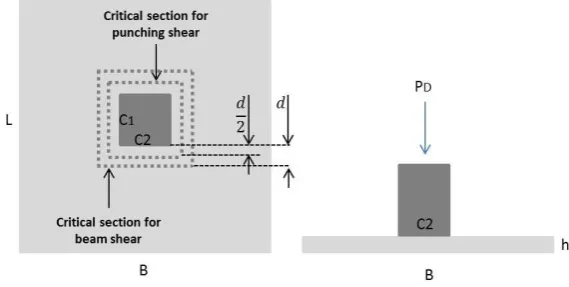
[image:11.595.85.227.286.448.2]Two models are constructed; one model will calculate the punch and beam shear in the concrete and one model will calculate the stresses in the concrete due to bending. The model used to calculate the bending stress is useful for three different loading conditions; loading on the interior of the slab, loading at the corner of the slab and loading on the edge of the slab (Figure 6). For the QS there is only one loading condition since the lean concrete layer is one big layer. For the SYIII the different loading conditions are however very useful since the foundation is build up out of multiple ground slabs. More information about the foundation can be found in Appendix D.
Figure 6: Loading conditions of concrete slabs.
The model that will calculate the shear stresses in the concrete is based on footing calculations. The concrete foundation represents the footing which is concentrically loaded by a SS under loading. This SS can be seen as the column. [10] The shear stresses due to a local load depend on:
Max allowable global floor pressure: 5mT/m2.
The foundation on top of the soil. For the calculation of the shear stresses in the concrete at the QS it is assumed that the lean concrete layer is split into slabs with the same width and length as the slabs on SYIII.
Floor surface of the support structure that is in contact with the concrete slab.
Properties of the used concrete.
Figure 7 shows the model used for shear and beam stresses.
[image:11.595.82.367.595.738.2]The model that will calculate the bending stresses in the concrete is based on Westergaard’s stress equations. [11] Westergaard’s equations are used in slab-on-grade pavement design. It calculates the max allowable wheel load, which is a local load. This report is however about high floor pressures due to loaded supports and not due to wheel loads.
Westergaard analysed three particular loading conditions (interior, edge and corner). For loading on the edge and corner of slabs, Westergaard only derived equations based on wheel loads, where it is assumed that the load is uniformly distributed over the area of a small circle with radius a. For interior loading of the slab, Westergaard also derived an equation that can be used in case of a uniformly distributed square area, which is the case at HCN.
A complete report which contains more information about the models and that will discuss the results into more detail than is done in the next section can be found in Appendix F.
3.2
Limitations
The two described models that will be used to calculate the allowable local floor pressure have some limitations. The model used to calculate the shear stresses in the concrete is based on footing calculations.
In case of footings, the column is always attached to the footing. In case of HCN, the supports are not attached to the concrete.
Footings are always beneath the surface and therefore there is always some type of soil on top of the footing. In case of HCN, the concrete forms the floor surface.
At the quay side, the foundation exists out of one big lean concrete layer. To perform shear calculations the concrete layer is divided in squares of 5 by 5 meter.
The Westergaard’s equations that are used to calculate the bending stresses in the concrete also have some limitations:
The vague definition of ‘Removed considerable distance’. For this study it is assumed that a considerable distance is equal to a distance of 1000mm between the center of the support to the edge.
Westergaard’s equations calculate the max allowable wheel load, which is a local load. This report is however about floor pressure due to loaded supports and not due to wheel loads, so it is an approximation.
The modulus of subgrade reaction (k-value) which is needed to calculate the bending stress in the concrete is always a constant. From the soil survey at the quay side it is found that there are a lot of different layers in the soil. For the calculations at HCN it is assumed that the upper two layers (backfilling stone and backfilling sand) have the biggest impact on this k-value. These two layers have a depth of at least 9 meters for the whole QS. An average of these two layers is used.
3.3
Results
With use of the two constructed models is it possible to calculate the max allowable local floor pressure for the QS and for the SYIII. The limitations of the models however have to be taken into account; therefore the complete Report about the local floor pressure should be checked by a civil bureau.
3.3.1
Storage Yard Phase III
Since the max allowable global floor pressure is 5mT/m2, the shear stress in the concrete will not cause any trouble. The shear stress will start causing trouble in case the total max allowable global floor pressure for one slab (125mT) is exerted to a surface area of mm ; the critical punching shear will become larger than the punching shear force resisted by the concrete. This will however never be the case for Huisman.
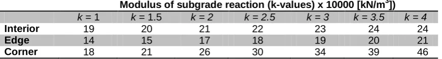
Modulus of subgrade reaction (k-values) x 10000 [kN/m3])
k = 1 k = 1.5 k = 2 k = 2.5 k = 3 k = 3.5 k = 4
Interior 19 20 21 22 23 24 24
Edge 14 15 17 18 19 20 21
Corner 18 21 26 30 34 39 46
Table 2: Max allowable local floor pressures at the storage yard for the three loading conditions. [mT/m2]
3.3.2
Quayside
For the QS punch will also not cause any problems; the bending stresses in the concrete will determine the max allowable local floor pressure. Since the lean concrete layer is just one big layer, only one loading condition is taken into account; the interior loading condition. For the calculation of the bending stress only the concrete layer is taken into account. The detritus layer, the sand layer and the precast concrete blocks are ignored. Results can be found in the table below.
Modulus of subgrade reaction (k-values) x 10000 [kN/m3])
k = 1 k = 1.5 k = 2 k = 2.5 k = 3 k = 3.5 k = 4
[image:13.595.75.511.71.130.2]Interior 74 78 81 83 86 88 90
Table 3: Max allowable local floor pressures at the quay side for the interior loading condition. [mT/m2]
At the moment the max allowable local floor pressure at the QS is 5mT/m2. According to models where punch shear, beam shear and bending in the lean concrete layer (with ignoring the other layers) are calculated, the local floor pressure can be increased significantly. The bending stress is for the lowest k-value (equal to 10.000kN/m3) not exceeding the critical stress in the concrete as long the local floor pressure is not exceeding 74mT/m2. Of course the max allowable global floor pressure of 5mT/m2 may not be exceeded.
4
Redesign Specifications
In chapter 3 it is found that the max allowable local floor pressure at SYIII can be increased by a factor off four up to 20mT/m2, as long as the max allowable global floor pressure is kept in check. During the evaluation of the product range in Chapter 2 it was found that the current average local floor pressure is already exceeding the prescribed floor pressure of 5mT/m2 by a factor of two up to 10mT/m2. Out of these values it can be concluded that the amount of SS used for the floor distribution can be halved. Remark is the assumed rigidly of the SBs used to distribute the floor pressure.
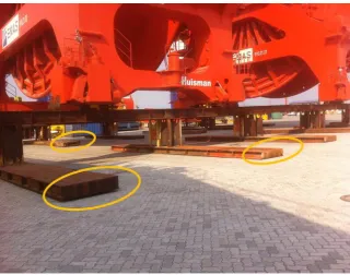
[image:14.595.79.400.267.519.2]What currently is done is the following; “replace 8meter long SBs with a height of 400mm by 12meter long SBs with a height of 310mm in case the contact area of the 8meter SBs with the floor surface is not enough to keep the floor pressure beneath the max allowable floor pressure”. In Figure 8 gaps between the ends of the SBs and the floor surface are shown to indicate that the distribution of the floor pressure is not uniformly. When the length of all the SBs is halved so that a local floor pressure of 20mT/m2 is reached this assumption will come closer to reality. Redesigning the SS used for floor pressure distribution can however lead to a better solution.
Figure 8: Gap between end of the SBs and the floor surface
The SSs used for floor pressure distribution are also used for the support of the product. In this chapter the requirements for the new SS that will be designed are discussed, but first information is given about some changes with respect to the current situation and about remarks/assumptions.
4.1
Changes
At the moment SBs are used for different functions. For the new support structures distinction will be made between the different functions to make sure the redesign will be designed most efficiently with respect to weight. The complete SS beneath a product exist, at the moment, out of multiple individual components (the simplest structure is build up out of three SBs and two WSSs). For the redesign it is considered if it is profitable to connect all the individual parts together so the complete SS exist out of one piece.
4.2
Remarks
The total amount of stock at HCN is equal to 2600mT. It is assumed that this total stock is used in the same way as the support structures in the product range.
The content of the report about the floor pressure first have to be verified before the results can be used. Therefore different local floor pressure scenarios will be evaluated during the design phase of the
allowable local floor pressure at the SYIII. With knowing that the allowable local floor pressure for WS B1A is varying between 40 and 200mT/m2, the third and last scenario of a local floor pressure of 40mT/m2 is embraced. For the third scenario the products will be transported directly from the workshops towards the QS.
During transport by SPMT it is assumed that the dimensions/shape of the redesign will not cause any troubles for the SPMT as long the loading conditions for the SPMT, as shown in ‘Drawing D00000306-03-100-01 SPMT China’ [5] are met. This assumption can be made since the load bearing beams are
over dimensioned with respect to the loading capacity of the SPMT.
4.3
Requirements
In this section all the requirements are set for the new design of the SSs. After discussing the requirements, all the information is available to start with the design phase of the SSs.
The maximum allowable local and global floor pressure should always be kept in check for the different scenarios.
The new SSs should be able to replace the SSs that are used for distribution of floor pressure and are used for support of the product at first level. The redesign is not intended to replace the SSs at higher level support.
Since 65% of the products are also supported at second level it should be able to place a second level support on top of the new SSs.
It should always be possible to transport the SSs together with the product by SPMT. With a SPMT height clearance of 1500mm and a width of 5500mm minimum dimensions for the SSs are defined.
For the new SSs distinction has to be made between complete SSs that will be transported with use of one and two SMPTs. SSs that need three SPMTs for transport are out of the design scope.
For the manufacturing of the redesign no machining operations or complex welding is allowed. This because of the price tag of the product.
The redesign should be manufactured out of steel37 and/or steel52. It is preferable that material is used that is already on stock at HCN.
Stability of the complete structure should be kept in check all the time.
5
Redesign Concepts
In this chapter different concepts for the new SS are discussed briefly. In Appendix G an elaborated version of the concept phase is given.
A complete SS consist out of three parts; a support beam, two columns and floor plates (Figure 9). The dashed lines show that there is a lot design space for each part. In the current situation is one complete SS constructed out of a number of stacking units (the WSSs and SBs). Advantage of these stacking units is the free design space for the complete SS. Another profit is the small storage area that is needed for the stacking units that are not in use. Big disadvantage however is that the same stacking units are used for different functions, which mean that they are not used most efficient with respect to weight.
[image:16.595.79.546.273.420.2]The new SS will be a complete SS where the support beam, two columns and floor plates are welded together. This way it is possible to design most efficient with respect to weight. Since the freedom of adjusting the complete SS (with use of more SBs or WSSs) is no longer available, distinction has to be made between different loading scenarios. It is for example possible to design SSs for different SWLs based on the product range or to design SSs with a SWL equal to the SWL of the SPMT.
Figure 9: Simplified body of complete SS
5.1
Support beam
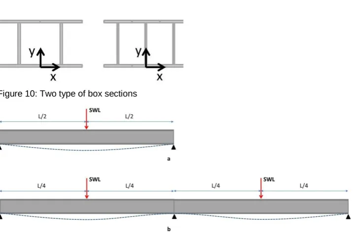
The support beam is subjected to two types of loading; point load in the middle of the beam and uniformly distributed load over the entire beam. Stresses due to bending and shear forces have to be kept in check together with the lateral torsional buckling (LTB). With neglecting the LTB the best section with respect to deflection is an I-beam. When the LTB is however taken into account, it is better to come up with a torsion box; the torsion box will give more stiffness to resist the LTB.
Because of the requirement that it should be possible to place a second level of support on top, it is preferable that the upper section of the beam is as wide as possible; a torsion box made out of I-beams becomes the best solution. The dimensions of the I-beams depend on the occurring stresses in the section, but it also depends on the design choices for the columns and at the plate material that is on stock at HCN.
Evaluation of the stock shows that St52 or Q345D will be used. Both have a yield stress starting from 345MPa. There are quite a number of plate thicknesses on stock, so that will not cause any bottlenecks.
In Microsoft Excel two models are created (‘Redesign single support’ and ‘Redesign double support’) to compare different kinds of support beams and column structures to come up with the most efficient support structure combination. Multiple SWLs (both point load and distributed load) are examined; this is based on the loading situations of the product range earlier discussed.
Figure 10: Two type of box sections
Figure 11: Deflection for two types of support beams
5.2
Column structure
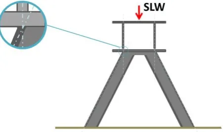
For the column structure, watched in the front view, distinction can be made between placing the column under a certain angle with respect to the vertical axis or to place the columns structure perpendicular with respect to the support beam. The first option can result in a shorter support beam since the length of the beam depends on the drive through width of the SPMT; see Figure 12 (5500mm plus 200mm tolerance). However to absorb the high stresses that will occur in the weld (stress concentration is pointed by red circle), large stiffeners are needed; reducing the support beam length is not possible and use of columns positioned vertical (when the SS is seen from the front) is preferred.
Figure 12: Column structure possibilities
Furthermore there are different options for the orientation of the column structure in the side view, different profiles are possible and distinction has to be made between the column structures of the two different models (column structures that support the end of the support beam and column structures that support the support beam in the middle).
Figure 13: Orientation of support columns
The stresses in the columns have to be kept in check all the time as well as failure to buckling.
5.3
Floor plate
6
Redesign results
In this chapter all the results obtained after evaluation of the different concepts and a final design is composed. Result off the different SS loading conditions together with the three floor pressure conditions is a 3x3 matrix with the reduction for every scenario.
6.1
Final design
In the final design is the support beam a box section constructed out of two I-beam profiles. Each column structure consists out of two I-beam columns under an angle of 30 degrees with the vertical axis. One end of the columns is welded to the support beam while the other end is welded to the floor plate. The flange of the column will be positioned in line with the web of the I-beam profile of the box section; Figure 14 shows the good force introduction between the support beam and the column structure. This force introduction is less in case of tube columns. A box section existing out of two I-beam profiles is chosen because it has a better stiffness versus weight ratio in comparison with a three I-beam profile section.
Figure 14: Positioning of columns with respect to support beam
The length of the support beam used for the first model, which will be transported by only one SPMT, is equal to 7 or 8 meters depending on the different scenarios. In case of the second model (transported by use of two SPMTs) the length is equal to 15 or 16 meters.
While all the column structures are constructed out of I-beam profiles, distinction is made between the SWL of the different column structures. The middle column structure in case of the second model has a higher SWL because of the variety of loading on top of that model. More information about choices made during the design phase and about the different loadings can be found in Appendix G.
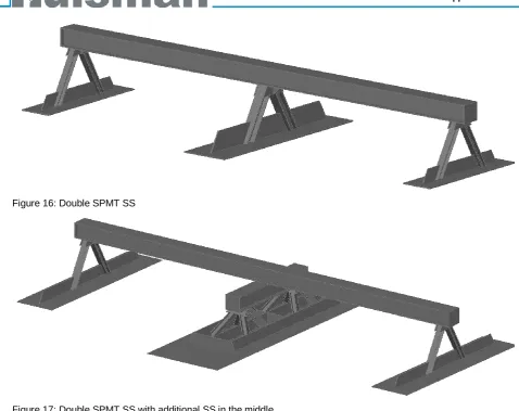
[image:19.595.85.311.252.385.2]As already discussed, are there different loading conditions on top of the SSs and different floor loading conditions. The floor plate should be able to uniformly distribute all the forces to the ground; this will result for some loading scenarios to a very large and heavy floor plate. A third SS model is needed to distribute the floor pressure uniformly to the floor in case the distance from the edge of the floor plate to the nearest point of the column is more than 2500mm. The different models are displayed in Figure 15, Figure 16 and Figure 17.
Figure 16: Double SPMT SS
Figure 17: Double SPMT SS with additional SS in the middle
6.2
Loading scenarios
At the moment, HCN uses a lot of the same load out configurations for a variety of products; a product is placed on a 8 meter SB (this way it is possible to transport the product), the SB is supported by two WSSs and the WSSs are on their turn placed on top of two 8 meter SBs. The 8 meter SB has a SWL applied in the middle of the board of 120mT. When the described load out configuration is loaded by that 120mT, the configuration is used reasonably efficient. When the configuration is however loaded by a product of about 20, 30 or 40mT (this is done multiple times at the moment) the ratio between support weight (about 18mT) and product weight becomes relatively high. Therefore not only SSs with a SWL equal to that of the existing SBs are examined but also SSs with lower SWL.
Figure 18: Load out of 300mT PMOC (left) and 1800mT HLMC (right) without using complete support structure
For the remaining complete SS, the loading of the SS due to the product is evaluated, for the twenty stored products that are taken into account it is found that 31 complete support structures need only one SPMT for transport and 13 complete support structures need two SPMTs. For the 31 single SPMT SSs the loading is divided into two groups; point load up to 50mT and point load between 50 and 100mT. 13 times the loading is less than 50mT and 18 complete support structures are loaded by a load between 50 and 100mT (one time an additional 8m SB is needed). For the 13 double complete support structures 9 times the structures is loaded by a point load less than 120mT and 4 times by a load between 120 and 160mT.
From the previous findings three different categories are composed. The first two scenarios are only based on information about the product range, while the third scenario is also based on the SWL of the SPMT.
1. - 13 SSs with a SWL of 50mT transported by one SPMT. - 18 SSs with a SWL of 100mT transported by one SPMT. - 9 SSs with a SWL of 2x120mT transported by two SPMTs. - 4 SSs with a SWL of 2x160mT transported by two SPMTs.
Figure 19: Loading scenario 1
2. - 31 SSs with a SWL of 100mT transported by one SPMT. - 13 SSs with a SWL of 2x160mT transported by two SPMTs.
Figure 20: Loading scenario 2
Figure 21: Loading scenario 3
All the safety loads are based on a point load in the middle of the support beam between two column supports.
6.3
Results
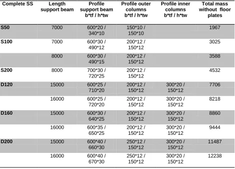
In order to determine the final reduction for all different scenarios an Excel sheet is constructed; “Reduction”. In this sheet multiple combinations of support beams and column structures are compared. Distinction is made between different support beams and column structures for the different floor pressure scenarios and loading scenarios. During the comparison of the beams and column structures the stresses in the material are taken into account and the mass of each component is kept as low as possible. This is done for all the above mentioned loading situations. Results are displayed in Table 4. Dimensions of the profile of support beam and column beams are also shown in this table, for information see Figure 22.
Complete SS Length support beam
Profile support beam
b*tf / h*tw
Profile outer columns b*tf / h*tw
Profile inner columns b*tf / h*tw
Total mass without floor
plates
S50 7000 600*20 /
340*10
150*10 / 150*10
1967
S100 7000 600*30 /
490*12
200*12 / 150*12
3025
8000 600*30 /
490*15
200*12 / 150*12
3588
S200 8000 700*30 /
720*25
200*12 / 150*12
4532
D120 15000 600*25 /
710*20 200*12 / 150*12 300*20 / 150*12 7706
16000 600*25 /
720*20 200*12 / 150*12 300*20 / 150*12 8218
D160 15000 600*30 /
640*25 200*12 / 150*12 300*20 / 150*12 8860
16000 600*35 /
650*25 200*12 / 150*12 300*20 / 150*12 9444
D200 15000 600*40 /
660*30 250*12 / 150*12 300*20 / 150*12 11487
16000 600*40 /
670*30 250*12 / 150*12 300*20 / 150*12 12238
Figure 22: Profile of support beam (left) and columns (right)
There are besides the different loading scenarios also the three floor pressure scenarios. These three floor pressure scenarios in combination with the loading scenarios resulting in different floor plates. The thickness of the floor plate is equal for all the different scenarios; 30mm. The amount of stiffeners that is used in order to reinforce the plate depends on the length of the floor plate. The stiffeners are needed for uniformly pressure distribution over the floor. The total amount of stiffeners used to reinforce the plate is equal to a certain percentage of the mass of the plate self. This percentage depends on the length of the plate, see Table 5. For floor plates longer than 6850mm an additional support structure is needed since reinforcement with only stiffeners is not sufficient.
Length of floor plate [mm]
Total weight of stiffeners attached to one plate [% of mass of floor plate]
0 – 4000 15
4000-6000 20
6000-6850 30
[image:23.595.75.545.304.388.2]6850 - Additional support structure
Table 5: Amount of stiffeners on floor plate
The combination of the loading scenarios together with the floor pressure scenarios results in a table containing the weight of the new design structure for every combination.
Loading scenario [mT]
Max allowable floor pressure [mT/m2]
10 20 40
S50 4810 3330 2650
S100 9750 5870 4390
S200 - 11000 8040
D120 26620* 15210 11110
D160 27850* 16440 12270
D200 - 24090 17040
Table 6: Weight of SS for all scenarios * Additional support is needed for the middle support column
The SSs used to support the 26 product, that forms the product range, represent a total weight of 1491mT. 1157mT is used to support the twenty products that are used to determine the previous mentioned loading scenarios. The new SS (only replaces the first level support) can replace 965mT of supports of the product range. The amount of the three before described cases can be extrapolated to the total amount of stock at HCN, see the table below.
Supports used for total product range
Supports used for products with complete
SSs
Supports used for first level of complete
SSs
Product range 1491 1157 965
Extrapolated to total stock
2600 2047 1683
Table 7: Three comparison categories
that it is not possible to replace the current SSs since the floor plates will become too big (SWL on every point on the beam is 200mT. With a floor pressure of 10mT/m2 this result in floor plates with dimension: 2x10m). Floor pressure scenario Loading scenario 1
10 mT/m2
2
20 mT/m2
3
40 mT/m2
[image:24.595.74.408.124.458.2]1 Scenario 1.1 618mT 37% 31% 24% Scenario 1.2 1031mT 61% 51% 40% Scenario 1.3 1186mT 71% 59% 46% 2 Scenario 2.1 486mT 29% 24% 19% Scenario 2.2 954mT 57% 47% 37% Scenario 2.3 1116mT 66% 55% 43% 3 Scenario 3.1 - Scenario 3.2 541mT 32% 27% 21% Scenario 3.3 862mT 51% 43% 33%
Conclusion
In conclusion, it is possible to reduce the amount of stock that is needed for the storage of product at the site of Huisman China significant. This reduction is based on two different investigations; investigation of the current floor pressure and designing new support structures that can be used more efficient with respect to weight.
Besides the reduction of stock results the new support structure into several other advantages. The new support structure exists out of one piece, therefore it takes less time to build a complete support structure and to transport one complete support structure. One complete support structure is less heavy in the new situation which means that the SWL of the SPMTs can be used more efficient. Since the new support structures are less heavily it is also more easily to handle them within the workshops.
The floor plates which will be specifically designed to distribute the floor pressure to the floor will distribute the floor pressure more uniformly to the floor than the spreader boards that are used at the moment.
Recommendations for Implementation
The investigation about the floor pressure has to be checked by a civil bureau. This doesn’t mean however that it is not possible to increase the floor pressure at any location at HCN. For the Workshop the distinction between the local and global max allowable floor pressure is already know.
Implementation of the max allowable local floor pressure according Appendix C will result in a direct reduction of stock. When the findings about the floor pressure are checked by a civil bureau it is still possible to adjust the floor pressure in the workshops according the conclusion of the civil bureau.
At the moment it is still difficult to decide which support structure type is the best. It is therefore recommended to perform a further investigation which will result in a final support structure which has a reduction of stock as result and maybe more advantages.
Recommendations for further investigation
The proposal for a new support structure presented in this report is not complete. This report provides a good basis but could use further expansion; further investigation should give more insights in the actual reduction of stock that is possible within HCN.
For further investigation it is recommended to design the support structures with keeping the SPMTs in mind. The costs associated with the SPMTs have, compared with the costs that are associated with the support structures, more impact on HCN. A support structure that will increase the efficiency of the SPMT can therefore maybe lead to a higher reduction of costs.
For the new internship assignment the following topics/requirements have to be taken into account:
1. All the different transportation scenarios (SPMTs located next to each other and in front of each other) result in different type of support structures. In consultation with the Management team of HCN, the Mechanical Engineering department and the workers in the workshop it should be possible to come up with a support structures that will increase the efficiency of the SPMTs and also lead to a significant reduction of stock. These two improvements will lead to significant savings.
2. During the new design phase of the support structures, the validity of the ‘floor pressure report at HCN’ has to be taken into account.
3. In further investigation the possibilities to build up a complete support structure out of separate components has to be evaluated. With use of separate components it is easier to modify the complete support structure with respect to the requirements for the products. Separate components also results in less storage space for the support structures in case they are not in use by HCN.
Since the mass of the support structure should be kept as low as possible the connection between the different components can cause difficulties.
4. During the design of the support structures attention has to be paid to the floor plates. It must be ensured that the floor plates will distribute the pressure to the floor as uniformly as possible.
References Report
5. AutoCad drawing D00000306-03-100-01, Self Propelled Modular Transport vehicle.
6. AutoCad drawing A07-20280-00-10F, Storage Yard.
7. Ministry of Construction of the Peoples Republic of China, Load code for the Design of Building Structures. 2002, Beijing, China Architecture & Building Press
8. FHC Dream Hall Project Geotechnical Survey Report (Abbreviation Version), Report for geology survey of dream hall.pdf.
9. AutoCad drawing A07-20260-B1-11, Ballast Pontoon.
10. Chapter 11: Footings, Available from:
http://site.iugaza.edu.ps/sshihada/files/2012/09/Footings-1.pdf
11. IOANNIDES A.M., THOMPSON M.R., and BARENBERG E.J. Westergaard Solutions Reconsidered. Available from:
Appendices
Appendix A
Inventory of stock
Appendix B
Usage of support structures
Appendix C
Local floor pressure workshop
Appendix D
Foundation storage yard and quay side
Appendix E
Loading of Ballast Pontoon
Appendix F
Report about Local floor pressure at HCN
Appendix G
Support Structure Design phase
Appendix A
Inventory of stock
Support structures on 17-03-2014
Spreader Boards
Project
number
Dimensions
(mm) l*w*h
Weight
(kg)
On ship
Behind
fence
Storage
Yard Other
side
Hall Other
side
Store
Storage
Yard
this
side
High
Hall
Low Hall Total
Total
Weight (T)
A08-00008-00-00B
8000*1200*400
5330
3
40
45
8
12
108
575.64
A08-00012-00-00B
12000*1440*310 12344
28
17
7
9
7
68
839.39
A07-00012-00-00A
12000*1224*524 13433
10
5
6
6
27
362.69
A07-00015-00-00A
15000*1224*524 16790
2
8
1
2
13
218.27
25080*1836*700 60000
4
4
240.00
5000*1224*524
5597
2
2
11.19
Supports
D00001180-01-100-01
1000*1000*400
425
8
22
6
14
4
1
5
60
25.50
"
1000*1000*500
453
27
45
5
4
7
10
3
101
45.75
"
1000*1000*750
523
25
36
3
14
3
25
9
115
60.15
"
1000*1000*1000 676
14
62
11
12
24
35
158
106.81
"
1000*1000*1250 771
20
35
4
4
4
67
51.66
"
1000*1000*1500 862
58
201
4
6
20
15
18
322
277.56
New workshop Supports
A14-26220-11-110A
1000*1000*2000 1634
8
8
13.07
"
1000*1000*2500 1741
10
10
17.41
Total
2845.10
Costs for material + production + transport is according to Bart Brill, cost
Appendix D
Foundation storage yard and quay side
The foundation of the storage yard Phase III exists out of a detritus layer with cast-in-situ concrete structures on top. The cast-in-situ structures have dimensions 5000x5000x250mm. The compressive strength of the concrete has a value of 30MPa and a flexural strength of 3.0MPa. There are no reinforcements used. The cast-in-situ concrete structures on storage yard Phase I have dimensions 5000x5000x200mm and have a compressive strength of 25MPa.The foundation of the quay side exists out of a layer of detritus followed by a lean concrete layer with a precast concrete block C50 on top. Main function of the lean concrete layer is to ensure a good distribution of the loads. The lean concrete has a compressive strength of 15MPa. The compressive strength of the detritus is for both the quay side and the storage yard equal to about 120KPa.
What is missing in the section view of the quayside is a sand layer of about 5cm between the precast concrete block and the lean concrete layer.
Appendix ELoading of Ballast Pontoon
When using a number of assumptions it is possible to make a small model where the max local force deck pressure is calculated. For the ballast pontoon of HCN this model is build up in Excel. Since the deck construction of the transport barges are always more or less the same, the results of the model should also give an idea about the possibility of making distinction between local and global deck pressure for other transport barges.
For the Ballast Pontoon, the longitudinal frame spacing is equal to 600mm and the transverse web spacing is equal to 2400mm. The Pontoon is split up into nine different tanks. Calculations are based on a small section of the deck above the tank located in the middle. Simplified reproduction of the pontoon is given in Figure 24. Figure 25 shows the 3D section of the deck that is used for the model. In this section is L equal to the width of the tank and also the length of the section, which is 6000mm and W is the width of the section of the deck that is taken into account. Because the web spacing is 2400mm, this is also the maximum value for W.
[image:38.595.104.447.251.412.2]Figure 24: Simplified reproduction of the Ballast Pontoon. Cross section of the Side view is displayed without stiffeners and webs.
Figure 25: 3D section of the deck.
[image:38.595.80.306.511.594.2]There are two loading situations (Figure 26); situation one where the walls of the tank are assumed to be rigid. In this situation it can be assumed that the web is clamped. For the second situation it is assumed that the walls have certain stiffness and therefore the web is assumed to be imposed. For both situations simple beam calculations are performed.
Figure 26: Loading situations of the deck. Rigid tank left, stiffness tank right.
With knowing the materials and dimensions of the web, the stiffeners and the plate it is possible to calculate the max point load F. Dimensions of the deck construction are given in the table below. The yield stress of the steel used is equal to 235Mpa.
Deck plate Thickness [mm]
15
Longitudinal frame: 210∙15 Web height [mm] Thickness [mm]
210 15
Transverse web fr20: 700∙10-250∙20 Web height [mm]
Thickness [mm]
Flange width [mm]
Thickness [mm]
[image:38.595.77.555.658.756.2]First step is to determine the center of gravity of the deck. The CoG depends on W, the width of the section that is taken into account. When the CoG is known and also the neutral axis it is possible to determine the maximal point load. For the first situation this is given by:
Error! Use the Home tab to apply Kop 7;Appendix to the text that you want to appear here.-1 For the second situations is the force given by:
Error! Use the Home tab to apply Kop 7;Appendix to the text that you want to appear here.-2 where
is the bending stress
I is the moment of inertia about the neutral axis
L is the length of the section
y is distance to the neutral axis in which the stress is calculated
For different values of W the forces for both the situations are given in table below together with the max load on that section according to the global deck pressure of 10mT/m2.
W [mm] [mT] [mT] [mT]
250 113 56 15
500 128 64 30
750 135 67 45
1000 139 69 60
1250 142 71 75
1500 143 72 90
1750 145 72 105
2000 146 73 120
2250 147 73 135
Appendix F Report about Local floor pressure at HCN
Huisman is a company operating globally with extensive experience in the design and manufacturing of heavy construction equipment for world’s leading on and offshore companies. The facility in Fujian Province (Xiamen area) in China is founded to facilitate customers in this region and to increase the overall production capacity. The production facility has been fully operational since April 2007 and delivers a significant contribution to the overall Huisman engineering and production capacity. Huisman China (HCN) is a production facility with a total area of 284,000 m2. Part of the terrain is the first quayside owned by an international company in China that is opened up in 2012. This quayside is specially constructed by Huisman to increase production area and be self-reliant for loading and unloading.Owing to the opening of the new quayside in 2012 a large storage area is obtained. In combination with requests of clients to store their products passed the delivery date, the amount of products currently stored have rapidly increased. During production and storage of the products, additional support structures (SS) are needed which results in a big stock. This stock exists out of two types of SS; workshop supports (WSS) and spreader boards (SB). The use of these two types of SS can be split up into mainly two categories; distribution of the floor pressure and supporting of the product. At the moment almost 1250mT of steel is used to distribute the pressures to the floor. HCN assumes that the max allowable global floor pressure is equal to the max allowable local floor pressure. This global floor pressure is determined by a local design institute; “Fujian Architectural & Light Textile Design Institute” and is based on a soil survey, ‘Report for geology survey of dream hall’ [1] performed at the quayside. (The soil survey of the soil beneath the storage yard is not available. Therefore it is assumed that the soil beneath the quayside and storage yard is the same. The foundation on top of the upper soil layer is not the same for the storage yard and quay side.) During this survey samples of all the different ground layers are taken. For all the layers, different tests are performed to determine the properties of that layer. When the results are known, the max allowable floor pressure is determined.3 The tests and calculations that are necessary to determine the max allowable floor pressure are according the Chinese code “Load code for the design of building structures” [13].
To be able to determine the correctness of the max allowable local floor pressure used at the moment first the foundations of the SYIII and QS are discussed. After that two models, one model based on footing design and one model based on slab-on-grade pavement design, will be constructed. These models can calculate the max allowable local floor pressures at both the areas at the site of HCN. The limitations of the models will be discussed afterwards followed by the results.
Foundation Storage Yard Phase III and Quayside
The foundation of the SYIII exists out of a detritus layer with cast-in-situ concrete structures on top. The cast-in-situ structures have dimensions 5000x5000x250mm (the thickness of 300mm in the figure in not correct). The compressive strength of the concrete has a value of 30MPa and a flexural strength of 3.0MPa. There are no reinforcements used.
The foundation of the QS exists out of a layer of detritus followed by a lean concrete layer with a precast concrete block C50 on top. Main function of the lean concrete layer is to ensure a good distribution of the loads. The lean concrete has a compressive strength of 15MPa. The compressive strength of the detritus is for both the quay side and the storage yard equal to about 120KPa.
What is missing in the section view of the QS is a sand layer of about 5cm between the precast concrete block and the lean concrete layer.
Figure 27: Foundation storage yard phase III and quayside
Calculation Models
The model used to determine the punch shear and beam shear is based on footing calculations. The cast-in-situ structure represents a square footing which is concentrically loaded by a support structure under loading. This support structure can be seen as the column. [14]
To determine the bending stresses in the concrete, a model based on Westergaard’s stress equations is used. [15] Westergaard’s equations are used in slab-on-grade pavement design. It calculates the max allowable wheel load. This report is however about floor pressure due to loaded supports and not due to wheel loads. That’s why this model provides only an approximation.
When the footing/ground slab is concentrically loaded and a uniform distribution of soil pressure is assumed, the max local allowable floor pressure is equal to:
Error! Use the Home tab to apply Kop 7;Appendix to the text that you want to appear here.-3 where A is the surface area of the ground slab and qall is the max global allowable floor pressure. Filling
in the dimensions of the footing and the global floor pressure, results in the possible allowable local floor pressure on top of the footing. If this local floor pressure is applicable depends, besides the bearing pressure of the soil, also on stresses in the concrete footing, the surface area on which the local floor pressure acts and the position where the local pressure engages to the footing.
Punch and beam shear
In case of a local floor pressure on a small surface area of the footing instead of the max allowable global floor pressure over the entire footing, large soil pressure is present under the footing which leads to high shear stresses. The shear capacity of the concrete must equal or exceeds the critical shear force produced by the local floor pressure
where is the strength reduction factor. 4 This is the case for both the punching shear force and the beam shear force.
The model that will be analysed is given in Figure 28. C1 and C2 are the dimensions of the ground
[image:42.595.86.401.152.293.2]surface of the support, L, B and h are the dimensions of the footing, d is the effective depth of the footing and Pd is the dead load which is applied to the support.
Figure 28: Critical shear sections
The critical section for punching shear is located at distance d/2 from the support structure. The effective depth is equal to the thickness of the slab minus 75mm. 5 The critical punching shear force can be evaluated using the following equation:
Error! Use the Home tab to apply Kop 7;Appendix to the text that you want to appear here.-5 Punching shear force resisted by concrete Vc is given as the smallest of:
Error! Use the Home tab to apply Kop 7;Appendix to the text that you want to appear here.-6
Error! Use the Home tab to apply Kop 7;Appendix to the text that you want to
4