273
©IJRASET: All Rights are Reserved
Nozzle Design Optimization to Reduce Noise
Sheldon Mascarenhas1, Shaik Amanullah2, Neeharika H 3, Prathik B.V4, Narendra51, 2, 3, 4, 5
Department of Aeronautical Engineering, Nitte Meenakshi Institute of Technology, Bangalore, India
Abstract: Spouts are every now and again used to control the rate of stream, speed, bearing, mass, shape, and additionally the weight of the stream that rises up out of them. A further rendition of a similar process is provided by a Nozzle. Understanding basic principles of fluid flow helps us to modify any nozzle to provide us desired results in terms of performance and optimization. A similar observation based study was made in order to understand how a convergent nozzle modification to a chevron nozzle can help us alter flow dynamics and its effect on generation of noise. A design fabrication, experimentation and analysis was done in order to understand as to why chevron nozzles are preferred to be used in combination with a turbofan engine. It also serves as testimony as to why a cheap alteration in design can provide better results than much more complex solutions whose constructional and operational viability is yet to be asserted.
Keywords:Convergent, chevron, nozzle, spout, acoustic power, decibel level, turbofan, bypass ratio, blower, pitot tube, settling chamber
I.INTRODUCTION
The spout is utilized to guide the turbine release gases to the environment at extreme speed to deliver the required push by extending the gases. The gases must grow totally and release sans vortex and hub stream. Warmth and weight vitality are changed over into speed, and subsequently, into push. Spout is characterized as a gadget planned to control the speed and course, or modification of a fluid stream (especially to grow speed) as it exits (or enters) an encased chamber or pipe. This sort of nozzle can be used create the required flow patter based on aerodynamics shaped by its ergonomics. The spout can be justly classified as convergent divergent and a combination of convergent divergent nozzle. A closer study of the case tells us that we can achieve a supersonic flow behavior using a convergent divergent nozzle, resulting in a choking at the throat. Nozzle design must also take into account both overexpansion and under expansion by the virtue of its geometry keeping in mind the external ambient pressure, so as to prevent losses in terms of thrust and preserve efficiency. Nozzles can also be constructed with a variable area in order to control the exit thrust, regulate it with help of its variable exit geometry, thus mustering up greater thrust when required solely by controlling the area of cross section. A Push inversion modification is a component to turn around the bearing of push power produced by the engine. By altering the push power course, the energy of an air ship can be decimated or drag can be expanded or in other words, it is similar to applying brakes. This instrument is activated for the most part after flying machine touchdown. All of the above given alterations address the problems with respect to fluid flow dynamics.
274
©IJRASET: All Rights are Reserved
through a change or a transitionary district. At last, at around eight distances across downstream, it changes into a locale of self-saving stream called the completely developed area. For subsonic planes, it is seen that the acoustic power per unit length approaches zero all around quickly in the completely created area. The majority of the power is discharged from the initial eight or ten stream measurements, with its greater part originating from the blending locale. The choppiness in the blending district is portrayed by little scale vortexes that outcome in high recurrence sounds, while the created area exhibits bigger swirls producing low recurrence sounds.
A simple solution to this noise generation would be too use smaller spouts which produce exit jet with lower contrast with respect to the ambient flow. Multiple solutions exist for eg: nano technology, increasing bypass ratio, using acoustic liners etc. However the solution being discussed is the chevron nozzle Chevron spouts are those spouts having the saw tooth design in the trailing edge of the airplane exhaust spout. Working of chevron spout is very basic, the hot fly is blended with the principle cold air stream coming legitimately from the motor fan. The chevrons are commonly triangular molded structure having a base, summit and a trailing edge so that they combine and radially inverse first and second surface limited there by. Every one of the chevrons is triangular in design, with a base, peak, side trailing edges meeting there between, and radially inverse first and second surfaces limited in this manner. The trailing edges of neighboring chevrons are dispersed horizontally separated to characterize particular veering spaces arranged in stream correspondence with the pipe. The chevrons have an inward form pivotally between the bases and summits which advances stream blending through the openings. Molded edges of the spout have a significant influence in smooth blending of the stream which essentially decreases choppiness (weight variance), a reason for commotion creation. Thus we intend to understand this behavior better.
II. OBJECTIVES
To study and compare Chevron and Convergent nozzle. To design fabricate and experiment with the two types of nozzles. To understand the guiding principles of flow inside the nozzles. To compare theoretical and practical results. To understand why Chevron nozzles are preferred to be used industrially.
III. METHODOLOGY
A. Design
[image:2.612.186.427.460.718.2]A chevron spout was structured by accepting the united spout as a source of perspective. The chevrons are designed as expansions to the 60mm distance across joined spout with a five-degree edge of entrance into the stream. The total length of the chevron nozzle was 214 mm. The spout leave proportional zone, created by the anticipated downstream zone, has been reduced due to infiltration. Another convergent nozzle had also been fabricated with a length of 194mm.
Figure 1: Chevron Nozzle
275
©IJRASET: All Rights are Reserved
[image:3.612.103.508.106.331.2]A 3D model was prepared using CATIA , to design a chevron nozzle with length 21.4cm having inlet diameter 9.86cm and outlet diameter 6cm, which has 8 spikes on the exit part.
Figure 3: Model of Chevron Nozzle
[image:3.612.119.499.378.535.2]Similarly a CATIA model was prepared for the convergent nozzle with total length of the nozzle being 19.4cm having inlet diameter 9.86cm and outlet diameter 6cm.
Figure 4: Model of Convergent Nozzle
B. Mesh
In order to analyze the above given chevron nozzle and the simple convergent nozzle, the 3D model was imported into ANSYS , and was meshed finely in with element dimensions nearing to 0.8mm.
[image:3.612.130.482.589.723.2]276
©IJRASET: All Rights are Reserved
Figure 6: Mesh of convergent Nozzle
C. Analysis
In order to perform a flow analysis and to determine their acoustic performance patterns they have been analyzed using FLUENT, and results have been observed using ANSYS post processing. The inlet velocity has been set as 3.5 m/s and it follows a viscous k epsilon model.
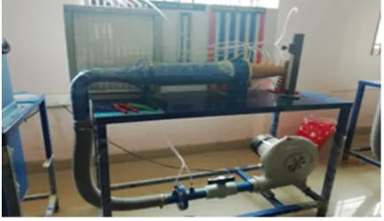
D. Experimental Setup
[image:4.612.116.498.75.211.2]The trial set up comprises of a blower unit fitted with the spout. The test segment spout is attached to a settling chamber which straightens the inlet stream. Six weight ports are set in the spouts which are associated at the multi-tube manometer. The blower has a control valve to control the progression of air.
Figure 7: Experimental Setup
Figure 8: Layout of Experimental Setup
[image:4.612.198.415.362.487.2]277
©IJRASET: All Rights are Reserved
E. Experimental Calculations
In order to calculate and observe the experimental results analytically we need to calculate the following formulas:
= 4
Pressure =ρw*g* Δh
Velocity=
Sound level = 20∗ 10*
Where, d = Diameter of the nozzle at any location(cm) g = Acceleration due to gravity (9.81m/s)
ρ w= Density of water (1000kg/m),
V = Velocity of flow at any location (m/s)
Δh= Manometer difference of water (cm)
P= pressure at each port, PO= atmospheric air pressure
The formulae helped us in calculating the required values for the experimental results, careful observed and validated with the computational analysis results.
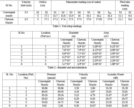
Sl No:
Velocity Inlet (m/s)
Orifice (cm)
Manometer reading (cm of water) Pitot tube reading
(cm) Convergent
nozzle
3.5 h1 h2 h1 h2 h3 h4 h5 h6 href h1 h2
5 17.1 15.7 15.8 15.9 16 16.1 16.2 16.3 11.1 9.4 Chevron
Nozzle
3.5 5 17.1 17.3 17.4 17.5 17.5 17.6 17.83 17.9 11.1 9.4
Table 1: Test setup readings
Sl.No: Location (Port no:)
Diameter (m)
[image:5.612.45.567.297.720.2]Area (m2) Convergent Nozzle Chevron Nozzle Convergent Nozzle Chevron Nozzle 1 1 8.2*10-2 8.9*10-2 5.28*10-3 6.22*10-3 2 2 7.6*10-2 7.9*10-2 4.13*10-3 4.90*10-3 3 3 6.8*10-2 7.1*10-2 6.63*10-3 3.95*10-3 4 4 6.2*10-2 6.2*10-2 3.03*10-3 3.01*10-3 5 5 5.7*10-2 5.3*10-2 2.55*10-3 2.20*10-3 6 6 5.1*10-2 4.9*10-2 2.04*10-3 1.88*10-3
Table 2 : diameter and area tabulation
Sl. No: Location (Port. No): Pressure (pascal) Velocity (m/s) Acoustic Power (dB) Convergent Nozzle Chevron Nozzle Convergent Nozzle Chevron Nozzle Convergent Nozzle Chevron Nozzle
1 1 58.86 58.86 3.59 3.08 35.39 35.39
2 2 49.05 49.05 4.18 3.87 33.81 33.81
3 3 39.24 39.24 5.23 4.79 31.87 31.87
4 4 29.43 29.43 6.29 6.29 29.37 29.37
5 5 19.62 14.71 7.44 8.61 23.35 23.35
6 6 9.81 3.26 9.30 10.07 19.83 16.85
278
©IJRASET: All Rights are Reserved
IV. RESULTS AND DISCUSSION
A. Visualization Results
[image:6.612.136.514.114.388.2]The scaled residuals of the flow analysis performed are displayed by the following figure.
Figure 9: Residual Graph
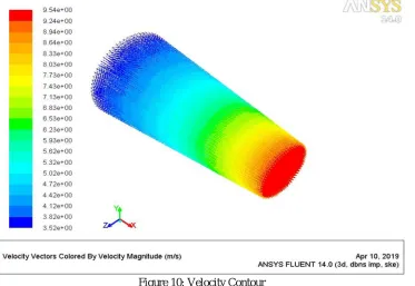
At inlet velocity, 3.5m/s, the maximum velocity obtained at the exit is 9.54m/s. As the area decreases velocity increases and vice-versa.
Figure 10: Velocity Contour
[image:6.612.143.516.432.689.2]279
[image:7.612.119.505.77.367.2]©IJRASET: All Rights are Reserved
Figure 11: Pressure Contour
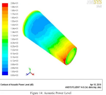
[image:7.612.142.484.385.692.2]The maximum acoustic power level obtained at the exit is 20.6dB.
Figure 14: Acoustic Power Level
280
[image:8.612.137.501.48.761.2]©IJRASET: All Rights are Reserved
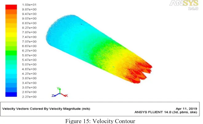
Figure 15: Velocity Contour
The post processed results shows that pressure is reducing along the length of the nozzle.
Figure 16: Pressure Contour
The maximum acoustic power level obtained at the exit is 17.4dB
[image:8.612.143.473.78.280.2]281
©IJRASET: All Rights are Reserved
B. Comparison
Comparison between the computational analysis values and the practically calculated values for the convergent nozzle. Sl No: Parameters Theoretical Practical % Error
1 Pressure 9.01 9.81 8.15
2 Velocity 9.54 9.30 2.51
3 Sound level 20.6 19.83 3.73
Comparison between the computational analysis values and the practically calculated values for the Chevron nozzle. Sl No: Parameters Theoretical Practical % Error
1 Pressure 2.98 3.26 8.58
2 Velocity 10.03 10.07 0.93
3 Sound level 17.4 16.85 3.16
V. CONCLUSIONS
This report has discussed the development of the chevron nozzle for jet noise reduction for high bypass ratio separate flow exhaust systems. Jet noise reduction is a very difficult task due to the constraints imposed by engine and aircraft system requirements. It is extremely difficult to reduce jet noise while not impacting anything else negatively. Chevrons are unique, as a jet noise reduction technology, in that they can have a relatively small impact on weight, performance, and operability.
We conclude that the shape optimizations of the chevron nozzle has a potential for the drop of turbulent mixing noise further, which is believed to be the leading component of jet noise for most aircraft. It is emphasized that jet noise remains a major component of engine noise. The Chevron technology has provided a modest relief for jet noise drop in aerospace applications. As a result of the analysis, a comparison was carried with baseline CD nozzle and chevron nozzle.
Finally, we performed both theoretical and experimental calculations; theoretically the sound level in convergent nozzle and chevron nozzle sound level are 20.6 dB and 17.4 Db respectively. Experimentally, sound level in convergent nozzle and chevron nozzle are 19.83 dB and 16.85 dB respectively. In both the cases we can conclude that the noise level in chevron nozzle has been reduced by 3 dB
REFERNCES
[1] RH.A Review on Jet Noise Reduction by Gp.Capt. Md Abdus Salam, Gp. Capt. NCChattopadhyay, Md Jalal Uddin Rumi, H.E.M. Zahidul ,Islam Eunus. [2] Noise Reduction in Jet Engine using Chevron Nozzle by Sadanandan, Dheeraj, Aswin, Akshay Kumar, Arjun Radhakrishnan.
[3] Jet noise reduction technology development inside Aircraft Engines by Steven Martens.
[4] Numerical Analysis of Chevron Nozzle with Various Configurations for Noise Reduction by Nevis Jenifer, Selva Preethi.