warwick.ac.uk/lib-publications
Original citation:
Wang, Wenjie and Thomas, P. J. (Peter J.). (2017) Low-frequency active noise control of an underwater large-scale structure with distributed giant magnetostrictive actuators. Sensors and Actuators A : Physical.
Permanent WRAP URL:
http://wrap.warwick.ac.uk/88956
Copyright and reuse:
The Warwick Research Archive Portal (WRAP) makes this work by researchers of the University of Warwick available open access under the following conditions. Copyright © and all moral rights to the version of the paper presented here belong to the individual author(s) and/or other copyright owners. To the extent reasonable and practicable the material made available in WRAP has been checked for eligibility before being made available.
Copies of full items can be used for personal research or study, educational, or not-for-profit purposes without prior permission or charge. Provided that the authors, title and full bibliographic details are credited, a hyperlink and/or URL is given for the original metadata page and the content is not changed in any way.
Publisher’s statement:
© 2017, Elsevier. Licensed under the Creative Commons Attribution-NonCommercial-NoDerivatives 4.0 International http://creativecommons.org/licenses/by-nc-nd/4.0/
A note on versions:
The version presented here may differ from the published version or, version of record, if you wish to cite this item you are advised to consult the publisher’s version. Please see the ‘permanent WRAP URL’ above for details on accessing the published version and note that access may require a subscription.
Low-frequency active noise control of an underwater large-scale
structure with distributed giant magnetostrictive actuators
Wenjie Wang1,2,*, P. J. Thomas2
1
Fluid and Acoustic Engineering Laboratory, Beihang University, Beijing, People’s Republic of
China
2 School of Engineering, University of Warwick, Coventry CV4 7AL, United Kingdom
*Corresponding author
E-mail: [email protected]
Highlights:
1.
A low-frequency miniaturized active control unit with giant
magnetostrictive material (GMM) is designed to less than 50 mm.
It can satisfy the particular underwater working requirements
such as high pressure, low frequency and high efficiency.
2.
A large-plate active acoustic structure is constructed with 16
giant magnetostrictive actuators. The thickness of the whole
active structure is 50mm.
3.
The active noise reduction performance of the active structure
is measured in an anechoic tank. The experimental results of the
absorption coefficients are much higher even under a high
pressure.
with a thickness of less than 50mm, is designed using giant magnetostrictive material (GMM). The noise reduction performance is measured with an active control system based on a multi-channel adaptive filter. The active control system is developed within a LabVIEW environment and can
achieve significant levels of noise reduction within time intervals of less than one second achieving absorption coefficients far exceeding 0.8 even under high pressures. The new active-control system
incorporates hardware and software components and represents a novel technology for low-frequency underwater noise reduction.
Key words: underwater large-scale acoustic structure; low frequency; active noise control; noise
reduction; giant magnetostrictive actuator
1.Introduction
Since the emergence of silent submarines, navies in the developed countries have primarily
focused on noise detection frequencies substantially below 2 kHz. In recent years active detection sonars with substantially low frequencies have been used regularly. Low-frequency detection sound
waves can not only achieve over the horizon (OTH) detection, but also lead to shell resonance, increase the target intensity, and overcome acoustic stealth. Thus, low frequency detection can leave the target fully exposed to the enemy in the monitoring system. It is of crucial importance for large
scale targets to resolve this safety hazard at low frequency.
Traditional passive acoustic structures are unable of response to incoming low-frequency sound
waves. This is due to sound reflection being governed by the material properties and the overall structure of the target. Active noise control techniques, however, offer an effective means to achieve low frequency noise reduction. Nevertheless, compared with the significant progress in the
aerodynamic field, active noise control is hardly used in underwater acoustics due to its harsh application requirements such as high pressure, light weight and high efficiency. Low-frequency
active control of a large-scale underwater target is rarely reported because of its special military background.
Structures for active noise control employing piezoelectric ceramics [1] and accelerometers
for underwater targets are referred to as "Smart Tiles”, this terminology was introduced by the Naval Civil Engineering Laboratory in 1996 [2-4]. Multifunctional active noise reduction structures can
have many concurrent functions such as active sound absorption, active sound insulation and active sound radiation control [5]. Related research based on PVDF thin films and Sonopanel composite structures, resulted in the development of active acoustic structures for underwater targets. Two
layers of PVDF thin films are used as signal separator to separate the incident wave and the reflected wave by means of a delay algorithm. The most efficient active noise- reduction effect can
be achieved with these signals by active methods as described by Howarth et al. [6-8] .
The most important component of signal separation and secondary sound source in active noise control are low-frequency acoustic transducers. Giant Magnetostrictive Materials (GMM) can be
designed for piston-type underwater acoustic transducers. This low frequency active sonar can transmit signals of 200 Hz whose sound intensity is 200 dB [9-10]. Macro Fiber Composites are
another new smart material for shell active noise control [11-12].
Frequently used materials are piezoelectric materials [13-16] (such as piezoelectric ceramics PZT, piezoelectric film PVDF) and magnetostrictive materials (such as rare earth material, giant
However, the disadvantages of ceramics are the required high driving voltage, small actuating amplitude, and the fragility of the material which limits its scope for underwater applications. Meanwhile, giant magnetostrictive material used in land high-frequency or ultra-high frequency
transducer fields and GMM has problems associated with heat transfer and cooling [17-20]. Although GMM do not need to cooling in water, it is difficult to use them at low frequencies
especially when the structural size of the Giant Magnetostrictive Actuator (GMA) is less than 50 mm.
In this paper, an active-control technology of an underwater large-scale target based on giant
magnetostrictive materials is studied in the low-frequency range. A GMA was designed step by step to meet these requirements. The multi-channel control software was developed within a LabVIEW
environment and achieves transient acoustic noise reduction. A limited area composed of active control units was used as the secondary sound source in a high pressure anechoic tank. The performance characteristics of the active noise control were evaluated by means of monitoring the
reflection coefficients.
2. Active unit design method
The active unit used a giant magnetostrictive actuator which is based on the magnetostrictive
effect. The basic parameters proposed in accordance with task requirements must be determined prior to the design of the magnetostrictive actuator. This section describes the design of an actuator
which can improve on the weakness of piezoelectric ceramics such as fragility, low efficiency and high drive voltage.
2.1 structure parameters of the active unit
Based on the design principle of an alternating current electromagnetic circuit, the giant magnetostrictive actuator under 2 kHz is designed with a Terfenol-D rod, as illustrated in Fig. 1, which can be applied to special requirements such as low frequency, high power and miniaturization.
Depending on the working conditions such as high pressure and current density, the diameter of the bare wire can be chosen from standard sizes. The diameter of the bare wire can be obtained from
the current density. The magnetic circuit will be working repeatedly within short time intervals. The coil thickness is:
I
n
n
H
e
2 14
(1)where, H is the magnetic field intensity. n1 and n2 are the number of turns per unit length and the unit thickness of layers respectively. I is the current.
The outer radius of the coil is:
21
1
2
r
e
e
N
r
j (2) where, r1 and r2 are the(3)
where, Lc is the length of the coil.
Set one end of the coil as the coordinate origin, the axis of the distribution of the magnetic field (approximation for multilayer coil) is:
(
4
)
ln
ln
{
2
2 / 1 2 2 1 1 2 / 1 2 2 2 2 2 / 1 2 2 1 1 2 / 1 2 2 2 2 2 1l
x
r
r
l
x
r
r
x
l
l
x
r
r
l
x
r
r
l
x
I
n
n
H
x
where, Hx is the magnetic field at position x.
Due to the alternating current (AC) in the coil, the total impedance coil consists of two parts, that is the resistance and the inductance.
(5) 2
4
nd
d
S
(6) where, R is resistance. Sd is the effective cross-sectional area of the wire and dn is the diameter of the bare wire. The resistance coefficient of the conductor is ρT=0.01191.
The calculation to determine the self-induction coefficient is, in general, complex. However, for the particular case of a simple straight solenoid coil, as considered in this paper, the Biot-Savart law
can be used to obtain an approximation of its value. Nevertheless, this approximation is larger than the actual value. This is so because the magnetic field of the coil is assumed to be uniform whereas the actual magnetic field is non-uniform and the discrepancy is particularly pronounced for short
coils. Due to the existing edge effects the field strength near the ends of the coil is only half its center value.
The self-induction coefficient is:
(7)
where, µ0 is the permeability of air, N is the total number of turns on the coil. Vc is the volume of the coil.
When the frequency of the alternating current within the coil is f, the impedance is
(8)
The total impedance of the coil is
2 2
L
X
R
Z
(9) The required voltage and consumption power of the coil is:(10)
The bias magnetic field of permanent magnets is used to eliminate Second Harmonic Generation
(SHG) of a Terfenol-D rod and provide mechanical movement of the Terfenol-D rod in a linear range. The calculations associated with the bias magnetic field are also very complex and the results obtained are generally not very accurate. For engineering application it is therefore a common
procedure to use an estimate in the first instance and, thereafter, the actual measurement provides a
)
)(
(
n
1L
n
2e
N
cd
T
r
r
N
S
R
(
1
2)
/
c c
L
V
N
L
0 2/
fL
X
L
2
R
I
P
IZ
reference for improvements. The estimate is obtained from the λ-H curve. If this estimate does not satisfy the requirements then the shape of the permanent magnet should be improved until the performance is satisfactory.
The design requirements and the steps outlined above define the geometric dimensions of the actuator. The diameter of radiation plate located in the end of the actuator drive rod is 150 mm and
its thickness is 2 mm. The total thickness of the GMA is only 40 mm which is ideal for thin low-frequency acoustic smart materials.
2.2 Finite element Simulation
Finite element analysis uses a mathematical approximation method to simulate the real physical condition such as geometry and loading conditions. We have conducted a finite element analysis, employing the ANSYS 14.0 software, to simulate our experiments computationally. and provide
theoretical support for the structural design and optimization. The GMA parameters are shown in Table 1.
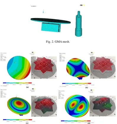
In Fig. 2, the element type used the three dimensional solid element solid 186 in finite element model of ANSYS 14.0. The axial key parts including rare earth rods, driver, permanent magnets and other components used more than 200,000 elements to guarantee the accuracy in the modeling
process of meshing, which can influence the GMA modal frequencies.
The boundary conditions of the finite element model are that the shell is constrained in all
degrees of freedom and the axial parts have axial freedom. The mode extraction method of Block Lanczos in ANSYS 14.0 is adopted to calculate the first four orders of resonance frequencies between 100 Hz to 3 kHz. The results of the simulations are compared to the experimental data in
Fig. 3.
For comparison, the resonance frequencies of the GMA is measured by a laser
scanning vibrometer (type: MLV-100). The experimental and computational results display, overall, identical trends, as shown in Table 2. This indicates that the experimental values are overall consistent with the theoretical ones.
2.3 Absorption coefficients testing
The sound absorption of the GMA unit is measured in the water-filled acoustic tube, illustrated in Fig. 4, by means of a set of adaptive control systems. The frequencies of the incident acoustic
signal ranged from 500 Hz to 2 kHz at the bottom of the acoustic tube. Sensors at the top of the tube receive the reflected sound waves from the surface of the GMA unit. Therefore, the sound absorption performance of the GMA unit can be evaluated, and the acoustic field can be displayed by means
of an oscilloscope. The reflection coefficient of the water-air interface is close to 1.0. The sound absorption coefficients of the GMA unit before and after control are shown in Fig. 5.
Fig. 5 reveals that, compared with sound absorption coefficients of the GMA unit before control, the coefficients after control are much higher. The average value of the coefficient after control lies above 0.85. The GMA units have a broadband noise reduction effect. In the low frequency range
structures.
3. Active large plate design method and active control system
3.1 Active large plate
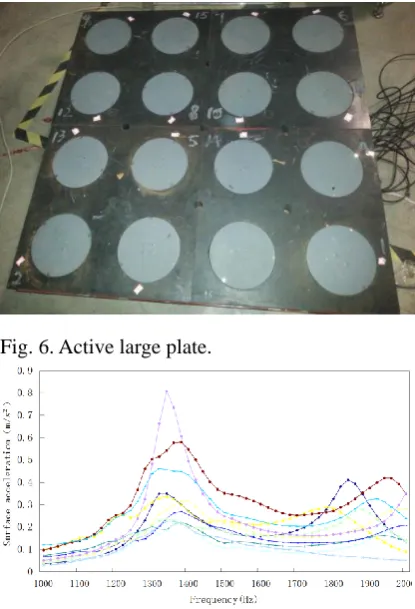
A large-plate sound source was used as a secondary source, or anti-source, which is constructed by uniformly distributed GMA units as shown in Fig. 6. These GMA units are embedded in rubber
material. This plate specimen size is 1 m × 1 m × 50 mm with 8 mm steel backing.
The surface acceleration of these sixteen units were measured by means of a surface vibration
analyzer (type: B&K 2513) and they were adjusted to the same phase. In Fig. 7 all units display the same trends of the frequency response characteristics. The main resonance frequency band ranges from 1.1 kHz to 2 kHz which is in accordance with the initial design purpose and application
frequency band.
3.2 Active control system
An active control theory has been developed adequately in the field of aerodynamics. The D-LMS algorithm in Eq. (11) is widely used in many active control methods [21]. The active control
system is developed based on the LabVIEW and DLMS layout illustrated in Fig. 8.
(
1)
( ) 2
( ) (
s)
W n
W n
e n X n k
(11)The primary microphone or hydrophone measures the signal x(n) from the primary source and the error sensor monitors the error signal e(n). When the error signal is reduced to the minimum
through an adaptive filter algorithm, noise reduction is achieved. The active control system has three branches (Background And Parameter Set, Impulse response of the secondary-path and ANC
System) as shown in Fig. 10.
4. Experiment apparatus and testing procedure
The active noise control experiments were conducted in an anechoic tank with a diameter of
4.5 m and a length of 25 m. The primary source used 127 circular array sound sources. The plate sound source is the secondary source or anti-source. The whole performance testing system is shown in Fig. 9. After the signals were emitted from the primary source, the signal can be separated to get
the incident signal and the reflected signal in the plate sound source. The controller analyzed and calculated the incident signal to send a secondary signal to the GMA units with the multi-channel
DLMS algorithm.
In order to evaluate active echo suppression performance under the condition of low frequencies, sound wave from primary sound noise source ranged from 500 Hz to 3 kHz. The entire testing
process was conducted under atmospheric pressure and for a hydrostatic pressure of 1 MPa. High hydrostatic pressure was achieved by water injection. After the secondary acoustic signals interfered
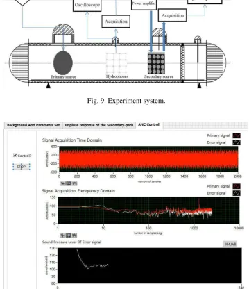
Prior to the experiments the tank was sealed and water was injected to increase the hydrostatic pressure to 1 MPa. The active noise control experiments were carried out at the stable pressure value of 0.96 MPa. The active control process is shown in Fig. 10. There are three spectra in Fig.10. The
first spectrum displays the time-domain results, the second spectrum shows the frequency-domain results and the third spectrum is the sound absorption coefficient of the active noise control. In the
first and second spectrum, the red line is the primary signal from a signal generator (type: Agilent 33220A) and the white line is the secondary sound signal. The sound pressure level of the error signal reduced from 128 dB to 103 dB when the incident frequency was 1.3 kHz. The convergence
time of the total active control was less than 1 s. The time domain and frequency domain of the signal can be found in Fig.10 and the current frequency is clearly displayed in the frequency domain.
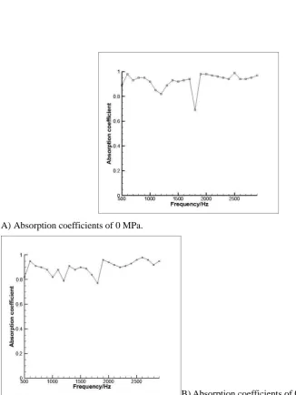
In the frequency band from 500 Hz~3 kHz, under atmospheric pressure, the active absorption coefficients of the large target in the large pressure anechoic tank is substantially higher than 0.9 at constant temperature as shown in Fig. 11. Meanwhile, the absorption coefficients under high
pressure is slightly smaller than those under hydrostatic pressure in Fig. 5. But these values are still more than 0.8 and the average coefficient was about 0.9.
Along with the absorption coefficient, the acoustical transmission property is also validated through the hydrophone array in Fig. 9. The sound pressure levels in front and back of the active plate sample are shown in Fig. 12. The distance from the hydrophone array to the active plate is 50
cm. The hydrophone array is composed of 16 hydrophones. The horizontal distance between two hydrophones is 20 cm and the longitudinal distance between two hydrophones is 0.40 m. The
hydrophone marked in red at Location [3,4] in the array is at the center point of the plate.
The acoustic fields of 800 Hz and 1500 Hz are shown in Fig. 12. The bright area is off-center due to the relative position. Because the array is close to the active plate, acoustic signals from the
array are near field signals of the plate. The controlled area is an approximate rectangle which is the region of active units. The sound pressure level of the transmission attenuation is more than 10 dB
even 20 dB through 58 mm at low frequencies. It has a substantial control effect even if the frequency is as low as 800 Hz.
5. Conclusion and discussion
In this paper, a thin low-frequency actuator with GMM was designed to satisfy special underwater requirements. A large active acoustic structure was constructed with distributed giant magnetostrictive actuators. An integrated underwater active control system based on LabVIEW was
proposed to achieve low frequency noise reduction even in deep water or under high pressure. This large acoustic structure with high absorption coefficients can provide a very important reference in
the context of the design of underwater equipment.
The objective of the present work was to evaluate the potential engineering application of the
acoustic characteristics of a large-scale underwater acoustic structure with giant magnetostrictive actuators in the low frequency band. This large acoustic structure consisted of GMA units that can
provide useful results in active noise reduction. To distinguish this from traditional passive noise reduction methods the current research with high absorption coefficients has a certain reference value for the underwater acoustical noise reduction. Meanwhile, experiments under high pressure
underwater active control experiments are the very important works which indicate that the exploratory in the lab can be used in the engineering application.
Future research will evaluate the active noise reduction performance under higher pressure (≤5MPa) and at other temperatures. Additionally, a monitoring system will be built to observe the noise reduction effect of the whole space. Experiments in lakes and in shallow seas would be
beneficial in order to achieve more realistic conditions mirroring real engineering applications.
Acknowledgments
This paper is supported by the China Postdoctoral Science Foundation (No. 2016M591046).
References and links
[1] J. F Tressler, R. E Newnham, W. J Hughes, Capped ceramic underwater sound projector: The "cymbal" transducer, Journal of the Acoustical Society of America. 105 (1999) 591-600
[2] R. D. Corsaro, B. Houston, J. Bucaro, Sensor actuator tile for underwater surface impedance control studies, Journal of the Acoustical Society of America. 102(1997) 1573-1581
[3] R. D. Corsaro, B. H. Houston, Sensor actuator panels for underwater acoustic control,
Proceedings of SPIE, 2779 (1996) 598-602
[4] R. D. Corsaro, B. H. Houston, J. D. Klunder, Integrated smart actuator containing a monolithic
conformed accelerometer, Proceedings of SPIE, 3044 (1997) 397-405
[5] F. D Shields, L. D. Lafleur, Smart acoustically active surfaces, Journal of the Acoustical Society of America. 102 (1997) 1559-1566
[6] T. R. Howarth, V. K. Varadan, X. Q. Bao, V. V. Varadan, Piezocomposite coating for active underwater sound reduction, Journal of the Acoustical Society of America. 2 (1991) 823-831
[7] T. R. Howarth, X. Q. Bao, V. V. Varadan, Digital time delay network for an active underwater acoustic coating, Journal of the Acoustical Society of America. 3 (1993) 1613-1619
[8] T. R. Howarth, Y. T. Robert, Electroacoustic Evaluations of 1-3 Piezocomposite SonoPanel
Materials, Ultrasonics, Ferroelectrics and Frequency Control. IEEE Transactions on 47 (2000) 886-894
[9] G. Engdahl, Handbook of Giant Magnetostrictive Materials, Sa Diego: Academic Press (2000) [10] J. H. Goldie, M. J. Gerver, J. Oleksy, Composite Terfenol-D Sonar Transducers, Proceedings
of SPIE, 3675 (1999) 223-234
[11] W. K. Wilkie, R. G Bryant, J. W. High, et.al., Low-cost piezocomposite actuator for structural control applications, Proceeding of SPIE, 3991 (2000) 323-334
[12] R. B. Williams, D. J. Inman, M. R. Schultz, et.al., Nonlinear tensile and shear behavior of macro fiber composite actuators., J. Compos. Mater. 38 (2004) 855-869
[13] Z. W. Chen, J. Q. Hu, Piezoelectric and dielectric properties of Bi0.5(Na0.84K0.16)0.5
TiO3-Ba(Zr0.01Ti0.96)O3 lead free piezoelectric ceramics, Advances in Applied Ceramics, 107 (2008) 222-226
[14] Huang Shouqing, Yang Yong, Liu Shouwen, Chu Xiangcheng, A large-diaphragm piezoelectric panel loudspeaker and its acoustic frequency response simulation method, Applied Acoustics, 125 (2017) 176-183
Shaped Substrate for Power Enhancement in MEMS Piezoelectric Energy Harvester, Journal of Circuits, Systems and Computers, 26 (2017) 9-21
[16] Yuan Xi, Zhu Song, Li Xianfang, Mechanical performance of piezoelectric fiber composites
and electroelastic field concentration near the electrode edges, Materials and Design 128 (2017) 71-79
[17] Zhu Yuchuan, Ji Liang, Theoretical and experimental investigations of the temperature and thermal deformation of a giant magnetostrictive actuator, Sensors and Actuators, A: Physical, 218 (2014) 167-178
[18] Zhou Can, Duan Jian, Deng Guiling, Li Junhui, Improved thermal characteristics of a novel magnetostrictive jet dispenser using water-cooling approach, Applied Thermal Engineering,
112 (2017) 1-7
[19] L. F. Cótica, S. Betal, C. T. Morrow, Thermal effects in magnetoelectric properties of NiFe2O4/Pb(Zr0.52Ti0.48)O3/NiFe2O4tri-layered composite, Integrated Ferroelectrics, 174
(2016) 203-209
[20] Sun Jianping, Wang Jianxin, Structure design and verification of thermo-acoustic refrigerator
driven by magnetostrictive transducer, Modern Electronics Technique, 39 (2016) 164-167 [21] H. S. Kim, Y. Park, Delayed-XLMS Algorithm: An Efficient ANC Algorithms Utilizing
Biographies
Dr. Wenjie Wang was born in Shandong, China, in 1988. He received the Ph.D. degree in fluid
and acoustic engineering from Beihang University, Beijing, China, in 2015. He is now a
postdoc in Fluid and Acoustic Engineering Laboratory, Beihang University. His main research
interests include underwater acoustics, aeroacoustics, intelligent systems with smart
materials and structures, piezoelectric devices and nonlinear dynamics
.Fig. 1. GMA structure.
Fig. 2. GMA mesh.
Fig. 4. GMA unit and acoustic tube.
[image:13.595.90.298.415.720.2]Fig. 5. Absorption coefficients of GMA unit.
Fig. 6. Active large plate.
Fig. 8. Active control procedure.
[image:14.595.115.475.325.742.2]Fig. 10. Testing process (f=1.3 kHz).
A)Absorption coefficients of 0 MPa.
[image:15.595.89.416.144.579.2]B) Absorption coefficients of 0.96 MPa.
Fig. 12. Array signals of front and back.
Table.1 Parameters of Terfenol-D Magnetostrictive Coefficient
(×10-9m/A) 2.0~3.2 Energy Density(/ kJ·m-3) 12~25
Resistivity(×10-5Ω·cm) 6.0 Elasticity Modulus
(×1010Pa) 2.5~3.5 Density(/ g·cm-3)
[image:16.595.105.500.554.602.2]9.25 Relative Permeability 3~15
Table 2 Results of simulation and experiment (Hz).
1st frequency 2nd frequency 3rd frequency 4th frequency Simulation 303.77 765.91 1270.9 2815.0