http://wrap.warwick.ac.uk
Original citation:
Mias, Christos and Freni, Angelos. (2015) Entire-domain basis function MoM formulation
for a substrate backed periodically loaded array of narrow strips. IEEE Transactions on
Antennas and Propagation, Volume 63 (Number 5). pp. 2325-2331. ISSN 0018-926X
Permanent WRAP url:
http://wrap.warwick.ac.uk/68047
Copyright and reuse:
The Warwick Research Archive Portal (WRAP) makes this work by researchers of the
University of Warwick available open access under the following conditions. Copyright ©
and all moral rights to the version of the paper presented here belong to the individual
author(s) and/or other copyright owners. To the extent reasonable and practicable the
material made available in WRAP has been checked for eligibility before being made
available.
Copies of full items can be used for personal research or study, educational, or not-for
profit purposes without prior permission or charge. Provided that the authors, title and
full bibliographic details are credited, a hyperlink and/or URL is given for the original
metadata page and the content is not changed in any way.
Publisher’s statement:
“© 2015 IEEE. Personal use of this material is permitted. Permission from IEEE must be
obtained for all other uses, in any current or future media, including reprinting
/republishing this material for advertising or promotional purposes, creating new
collective works, for resale or redistribution to servers or lists, or reuse of any
copyrighted component of this work in other works.”
A note on versions:
The version presented here may differ from the published version or, version of record, if
you wish to cite this item you are advised to consult the publisher’s version. Please see
the ‘permanent WRAP url’ above for details on accessing the published version and note
that access may require a subscription.
Abstract— J.R. Wait’s en tire-domain basis function method of moments matrix formulation for modeling scattering from periodically loaded wires in free space is modified using the current edge approximation and extended to include a multilayer substrate. From this matrix formulation, novel analytical formulations for the current and the effective transfer impedance are obtained. The convergence of the matrix and analytical formulations is improved with the aid of an expression by A.L. VanKoughnett. Furthermore, for the case of an electrically dense array, the analytical expression of the effective transfer impedance leads to a simple impedance model which is more general than previously published expressions.
Index Terms—Strip scatterers, electromagnetic scattering by periodic structures, wire grids
I. INTRODUCTION
THE design theory of periodically loaded arrays of narrow strips is of particular significance since such devices can have useful properties as frequency selective surfaces (FSS) and antenna arrays [1][2]. The accurate modeling of periodically loaded structures can be achieved using versatile subdomain basis function numerical techniques, often found in commercial software, such as the finite element method and the method of moments (MoM). However, the use of tailored electromagnetic and equivalent circuit methods [3] improves one’s physical insight into the electromagnetic behavior of these structures. In addition, these methods are often simpler to implement and faster than commercial software and hence more amenable to hybridization with other techniques. One such tailored method is the formulation of J.R. Wait [4] for modeling scattering from periodically loaded thin wire grids in free space. As stated in [5], the procedure is equivalent to a MoM solution of Pocklington’s equation for thin wires using entire domain sinuosoidal expansion and testing functions. We demonstrated recently, [6][7], that this thin wire formulation, and its extension to orthogonal grids can provide useful insight into the behavior of connected arrays and FSS, particularly for electrically dense arrays. With the aim to extend further the insight on FSS, we extend in this work Wait’s formulation to include the presence of a multilayer substrate (Fig. 1). This is shown in section II. Furthermore, instead of using the approximate kernel formulation with its well described solution issues [8][9], we employ the narrow strip current with the edge
Manuscript received June 11, 2014
C. Mias is with the University of Warwick, Coventry, CV4 7AL, United Kingdom, (e-mail: [email protected]; phone: 00442476522343; fax: 00442476418922).
[image:2.595.325.530.99.293.2]A. Freni is with the Department of Information Engineering, University of Florence, I-50139 Firenze, Italy.
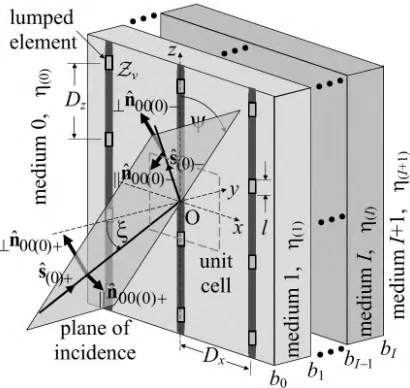
Fig. 1. Geometry of the substrate backed periodically loaded array of narrow strips.
condition [10][11] which was linked by C.M Butler to the exact kernel [12].
In section III, we improve the convergence of the section II formulation following a methodology used for thin wire arrays [4],[5]. Specifically, to apply this methodology to our narrow strip problem and at the same time gain insight into the behavior of our substrate backed periodically loaded arrays, we exploit a Bessel series equation obtained by A.L. VanKoughnett [13]. Thence, a novel simple expression for the effective transfer impedance for electrically dense arrays is obtained. This expression indicates the potential of Wait’s entire-domain basis function MoM formulation to provide physical insight into the behavior of periodically loaded strip arrays. Finally, numerical results are presented in section IV.
II. FORMULATION WITHEDGECONDITIONCURRENT AND
MULTILAYERSUBSTRATE
The periodically loaded narrow-strip configuration, with periodsDxandDz, is defined in Fig. 1. It is assumed to lie in the
x-zplane, at the interface between medium 0 and medium 1 (b0= 0). Medium 0 is assumed to be lossless with permittivity
(0)=0r(0), permeability(0)=0r(0), intrinsic impedance(0)
and wavenumber kr(0). However, the layers of the multilayer
substrate can be lossy. The incident electric field Einc, with amplitude E0, is assumed to be either parallel (= || ) or
perpendicularly (=) polarized and it is given by [7]
00(0)
ˆ
0 ˆ
)
(R (0) (0) n
Einc E e jkr s R (1)
where sˆ(0) sx(0)xˆsy(0)yˆsz(0)zˆ is the direction vector with sx(0)= sinsin, sy(0)= cos and sz(0)= sincos. The
polarization unit vector nˆ00(0) is defined in eq. (2) of [7]. Following [11], thez-directed surface strip current density is assumed to be
Entire-domain basis function MoM
formulation for a substrate backed periodically
loaded array of narrow strips
) (
1
2/2 ( ) (0) (0) (0) ) / 2 ( 1 ) ,
( jk s x s z
s z x r e z I w x w z x
J
(2) wherewis the strip width.I(z) is the z-periodic part of the current. Through a Fourier series expansion,
m D mz j me zA z
I ( ) 2 / , (3)
it is expressed in terms of the current harmonic amplitudesAm;
m being the integer index of periodicity along thez-direction. As in [4], the current harmonic amplitudes Am are the unknowns of the formulation. Their values are determined by solving matrix equation (12) or from the analytic expressions (13) and (14).
Unlike [3], the whole of (2) is used in the integration over the surface of the narrow strip to obtain, using eq. (F.3) of [1], the radiated electric field,Esc, which is given by
) ˆ ˆ ( ) ( 2 ) 0 ( || ) 0 ( || ) 0 ( ) 0 ( 0 ) 0 ( ˆ ) 0
( (0) (0)
mq mqz mq mqz xm q mqy
jk m x sc n n D qw J r e A D mq r n n E R r (4)
Thus, our electric field expression contains zero order Bessel functions of the first kind of the formJ0(qw/Dx) whereqis the integer index of periodicity along thex-direction. These Bessel terms have practically the same numerical value as those of [3] for a narrow strip. We follow [1] in defining the propagation and polarization of the fields. Specifically, the direction vector of the mqth harmonic in medium is defined as
z y
x
rˆmq() rqx()ˆrmqy()ˆrmz()ˆ and its components can be obtained from eqs. (4.24), (5.3)-(5.5) of [1]. In addition, subscripts on the right include the harmonic order, “mand/or q”, the cartesian coordinate “x,y,z” for vector components, and the medium index which appears within round brackets. The direction of polarization, parallel (||) or perpendicular (), of the mqth harmonic in medium is represented by the
polarization unit vectors ||nˆmq() and nˆmq() , respectively. These vectors are defined in eqs. (4.55) and (4.56) of [1]. ||nmqz() and nmqz(), which appear in (4) for= 0, are theirz-components . As in [1], thesubscripts refer to the harmonic direction vector signs above. The polarization subscripts (||,) appear on the left of a variable. It is to be noted that the radiated field in (4) contains both polarizations.
A per unit length load impedanceZLis defined in terms of the lumped element impedancevasZL(z) =v/l.vis assumed to be uniformly distributed along the element length l. ZLis periodic and can be expressed as a summation of Fourier series terms [7],
n D nz j nL z Z e z
Z ( ) 2 / (5)
withZn= [(1)n(v/Dz) sin(nl/Dz)]/(nl/Dz) andZ0=v/Dz. As indicated in [6], multiple lumped elements can be defined along the strips by modifyingZnaccordingly.
The boundary condition in the reference strip (q= 0),
eq. (14) of [4], is applied atRb=Rb(0,0,z)
inc ref inc sc ref sc
ZLIb R R z E E E
E ( ) ( ) ˆ (6)
The current I in (6) is obtained by integrating Js(x,z), of equation (2), over the strip widthw,
z z s r jk w x r z z s r jk e z I s k J e z I z
I (0) (0)
2 ) 0 ( ) 0 ( 0 ) 0 ( ) 0 ( ( ) ( ) ) ( ) ( (7) where the approximation holds for an electrically narrow strip width. For simplicity, this approximation is assumed in our formulation. Following the approach in [1] for including the multilayer substrate in the reflected electric field expressions, the reflection of the incident electric field from the multilayer substrate,Eref(inc), is given by
00(0)
ˆ 0 ) 0 ( 00 )
( (0)(0) nˆ
Eref inc e E e jkr s R (8)
and the reflection of the radiated electric field from the multilayer substrate,Eref(sc), is
) ˆ ˆ ( ) ( 2 ) 0 ( || ) 0 ( || ) 0 ( || ) 0 ( ) 0 ( ) 0 ( 0 , ˆ ) 0 ( )
( (0) (0)
mq mqz e mq mq mqz e mq x m q mqyjk m x sc ref n n D qw J r e A D mq r n n E R r (9) The effective reflection coefficient ,||emq() of the (m,q)th
harmonic at the interface between mediaand+1 is defined in eq. D.14 of [1]. Inserting eqs. (1), (4-5) and (7-9) in (6) and following the methodology of [4], we obtain
0 ' ˆ m n n m n m
m A Z A
Z
(10)where
1e00(0)
n00z(0) E0 and
)] 1 ( ) 1 ( [ ) / ( 2 ˆ ) 0 ( || 2 ) 0 ( || ) 0 ( 2 ) 0 ( ) 0 ( 0 ) 0 ( 0 e mq mqz e mq mqz mq x q x m n n D qw J D j Z Z (11) excludes n= 0. In medium , the propagation constant is mq()=jkr()rmqy().
The unknown current harmonic amplitude values Am are evaluated by solving the matrix equation,
0 0 0 0 ˆ ˆ ˆ ˆ ˆ 2 1 0 1 2 4 3 2 1 2 3 2 1 1 1 2 1 0 1 2 1 1 1 2 3 2 1 2 3 4 A A A A A Z Z Z Z Z Z Z Z Z Z Z Z Z Z Z Z Z Z Z Z Z Z Z Z Z (12)
eq. (11). A numerical example is considered in section IV. For the configuration in Fig. 1, if infinitesimal lumped elements are assumed then Zn= (1)nZ0 and, due to the
similarity of (12) to eq. (9) of [6], the derivation procedure described in [6] is used to obtain the following analytical expressions for the current harmonic amplitudesAm. Form0,
m z e m m Z Z A E n A ' ˆ ' ˆ ) 1 ( ) 1
( | |1 00(0) 00 (0) 0 0 0
(13)
and form= 0,
1 0 0 ) 0 ( 00 ) 0 ( 00 0 ' ˆ ) 1 ( Z z e S Z E n A (14) with
ˆ'1 ' 1
0 Z
Z
SZ (15)
where Zˆ'mZˆmZ0.excludes= 0.
From the definition of eq. (23) in [4] we obtain, using eqs. (1), (4), (8-9) and (14), the effective transfer impedance,Zg, of our multilayer substrate backed strip array structure,
e
z e z y z y Z x g n n s s s S Z D Z ) 0 ( 00 || 2 ) 0 ( 00 || ) 0 ( 00 2 ) 0 ( 00 ) 0 ( ) 0 ( 2 ) 0 ( ) 0 ( ) 0 ( 1 0 2 ) 1 ( 2 ) ' ˆ ( (16)
ForE-plane (||,sx(0)= 0), andH-plane (,sz(0)= 0) incidence,
Zgis the transmission line equivalent circuit impedance of the periodically loaded strip array structure.
Both the matrix equation (12) and the analytical (13-14) formulations depend onẐmand hence the summation in (11) is considered in the next section.
III. IMPROVINGCONVERGENCEANDGAININGINSIGHTUSING
THEVANKOUGHNETTEQUATION
To improve the convergence of the summation in (11) and gain further physical insight, the convergence methodology in [4] is used. To use this methodology, the asymptotic expressions (as q ) of terms in (11) are obtained, i.e. mq(0)2|q|/Dx,
2 ) 0 ( mqz n
1, ||nmqz2 (0)rmz2(0) , ,||emq(0)
) ( ) 0 ( || , where ) 0 ( ) 0 ( ) 1 ( ) 1 ( ) 0 ( ) 0 ( ) 1 ( ) 1 ( ) ( ) 0 ( r r r r k k k k , (17) ) 0 ( ) 1 ( ) 1 ( ) 0 ( ) 0 ( ) 1 ( ) 1 ( ) 0 ( ) ( ) 0 ( || r r r r k k k k . (18)
The expressions (17) and (18), which are independent of the angle of incidence and harmonic order, are obtained using the asymptotic expression rmqy(1)/rmqy(0)kr(0)/kr(1) and by
assuming that the exponential terms in the effective reflection coefficient ,||emq(0) expression are essentially zero. The latter is valid since if q is large enough, no matter what the thickness of medium 1, the corresponding q harmonics will
evanesce to zero before reaching medium 2. By replacing the terms in (11) by their asymptotic expressions above leads to a summation in (11) that can be approximated by a closed form expression with only a few terms. This is achieved by using the following equation by VanKoughnett [13],
] ) O( 2 [ | | ) 2 (
' 0 W S 6
q qS J q
(19)whereexcludesq= 0,S = w/(2Dx) and
4 2 (3/16) (4)
) 2 ( ) 2 / 1 ( )] /( 1
ln[ S S S
W (20)
with() being the Riemann zeta function. By ignoring theSu power terms in (19) for u6 and following the convergence methodology in [4], (11) is re-expressed as follows:
e m z m e m z m mz m m m x mz iso m mz x mz x m n n r W D r r W D r D j Z Z ) 0 ( 0 || 2 ) 0 ( 0 || ) 0 ( 0 2 ) 0 ( 0 2 ) 0 ( ) 0 ( 0 ) ( || ) ( ) ( ) 0 ( || 2 ) 0 ( ) ( ) 0 ( ) ( 2 ) 0 ( 2 ) 0 ( ) 0 ( 0 1 1 ) 1 ( ) 1 ( 2 ˆ (21) where
| | 1 1 ' 2 ) 0 ( 0 ) ( q D qw J x D mq x q iso m (22)
x D q mq e mq mqz x q m n D qw J | | 2 ) ( ) 0 ( ) 0 ( ) 0 ( 2 ) 0 ( 0 ) ( ' (23)
x D q mz mq e mq mqz x q m r n D qw J | | 2 ) ( ) 0 ( || 2 ) 0 ( ) 0 ( ) 0 ( || 2 ) 0 ( || 0 ) ( || ' (24) A demonstration of the improved convergence of (21) over (11) is shown in section IV. The above convergence procedure using the VanKoughnett equation can also be applied to eq. (10) of [3].Following [6], an electrically small period and a sufficiently smallZ0are assumed such that: (i)SZ1Z0in (16); and (ii) the
terms in (21) form =0 can be ignored. Hence (16) simplifies to
1 sin cos (1 )
2 ) ( ) 0 ( || 2 2 ) ( ) 0 ( ) 0 (
0
D Z j DW
Zg x x
(25) For E/H-plane incidence it is worth noting that (25) simplifies to the strip array formulae which are obtained from the capacitive grid eqs. (10-11) of [14] using eq. (7) of [14] assuming thatw/Dxis sufficiently small such thatWin (20) is approximated by its first term and sin(x)xin eq. (4) of [14]. It is also assumed in [14] that medium 0 is free space and medium 1 is a lossless dielectric of relative permittivityr(the relative permeability is assumed to be unity). Thus, (25) is a more general expression than the strip array expressions of [14].
effective permittivity term in [14], is attributed to the interaction of the evanescent harmonics with the first interface at b0 only as indicated by the presence of the asymptotic
expressions (17) and (18).
Moreover, by using a capacitor as a lumped element, a bandstop FSS can be obtained. It was indicated in [7] that the E-plane resonance frequency stability with respect to the angle of incidence improves by adding a lumped element inductance sufficiently larger than the wire inductance; this can be deduced from (25) too. Specifically, by increasing the inductive part of the load, the impedance Zg becomes less sensitive to the variations of the square bracket term of (25). It can also be deduced from (25) that the E-plane resonance frequency stability also improves as ||((0)) 1; i.e. by increasing the relative permittivity of a dielectric substrate.
IV. NUMERICALRESULTS
To numerically test the formulation, an arbitary bandstop FSS example is considered in which the lumped element is a capacitor of valueC= 0.5 pF, hencev= (jC)1. The lumped element length isl= 0.5 mm, the periods areDx=Dz= 30 mm and the narrow strip width is w= 0.24 mm. The substrate consists of two layers. Medium 1 has a thickness of 5 mm, relative permittivityr(1)= 4, relative permeabilityr(1)= 4 (this
value is employed for purely numerical comparison as it does not occur naturally) and conductivity (1)= 0.05 S/m. For
medium 2, the thickness is 2 mm, r(2)= 2, r(2)= 1 and
(2)= 0.2 S/m. The incident plane wave amplitude is
E0= 1 V/m. The medium 0 is assumed to be free space and the
medium 3 is assumed to be identical to medium 0. The matrix equation is obtained from (10) by assumingMmMwhere M= 10 in this example. As in [6][7], for any valuem=, the range of n in (10) is (M)n(M+). For the analytic solution,M M in (15).
The scattering characteristics of the structure considered are shown in Figs. 2-4. There is a very good agreement among the the MoM matrix solution, the MoM analytical solution and the CST solution for both, parallel and perpendicular, polarization incidences. It has to be noted that in the CST simulation input and output ports are specified at a distance of 20 mm from the strips and scattering parameter results are obtained. Hence, for convenience when comparing results, the co-polarized (=) and cross-polarized ( ) transmission coefficient, T, of the propagating fundamental harmonic is defined here as the ratio of the transmitted field at Rout=R(x,yobs,z) over the incident field at Rin=R(x,yobs,z), yobs= 20 mm. The symbols
=,|| and =,|| represent the incident and transmitted wave polarization, respectively. In addition, the reflection coefficient, R, of the propagating fundamental harmonic is defined here as the ratio of the reflected field at Rinover the incident field atRin. The expressions of these coefficients are:
obs y r s y
k j tot
in inc
out tran
e E
F E
t E
E
T 2 (0) (0)
0 0
) (
)
(
R R
(26) and
(a)
(b)
(c)
[image:5.595.327.514.84.664.2](d)
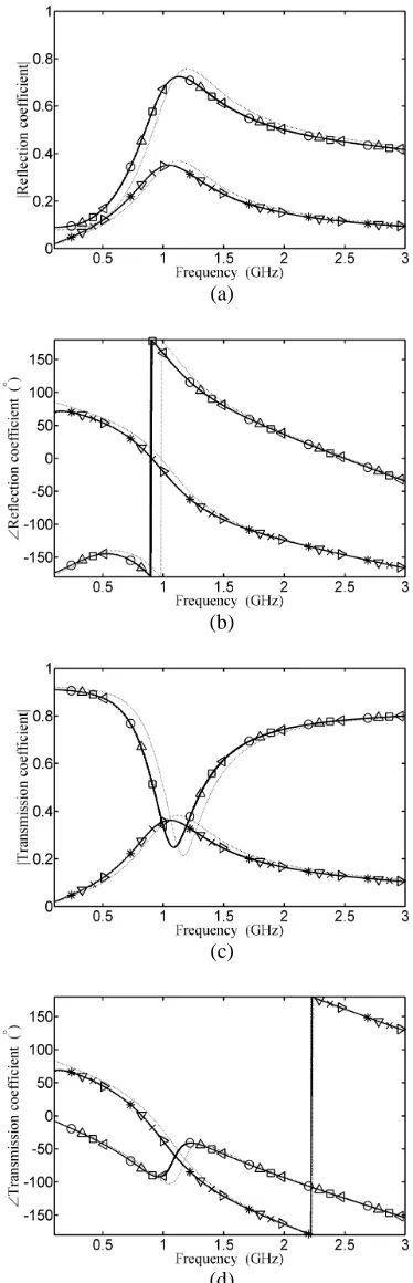
Fig. 2. Plots of reflection and transmission coefficient versus frequency for parallel polarization; (a,c) magnitude and (b,d) phase. Angles of incidence:
(a)
(b)
(c)
[image:6.595.68.256.80.675.2](d)
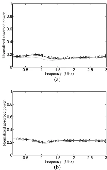
Fig. 3. Plots of reflection and transmission coefficient versus frequency for perpendicular polarization; (a,c) magnitude and (b,d) phase. Angles of incidence:= 45,= 22.5. CST: dashed line. MoM: solid line with symbols; co-polarized and cross-polarized results: analytical-VanKoughnett:/; analytical-Bessel:/; matrix-VanKoughnett:/; matrix-Bessel:/. The dashed and solid lines are visibly indistinguishable. Dotted line: based on simple expression ofZg, eq. (25).
(a)
[image:6.595.330.512.83.371.2](b)
Fig. 4. Plots of normalized absorbed power versus frequency for (a) parallel and (b) perpendicular polarization. Angles of incidence:= 45,= 22.5. CST: dashed line. MoM: solid line with symbols; analytical-VanKoughnett:; analytical-Bessel:; matrix-VanKoughnett:; matrix-Bessel:. The dashed and solid lines are visibly indistinguishable. Dotted line: based on simple expression ofZg, eq. (25).
obs y
r s y
k j
e e
in inc
in refl
e
E F
E E R
) 0 ( ) 0 (
2
0 ) 0 ( 00 )
0 ( 00
) 1
( )
( ) (
R R
(27) where F=(0)A0n00z(0)/ (2Dxsy(0)), is the Kronecker
delta, and from eq. (D.17) of [1],
I
i
d r jk I
i e i b r jk b r jk
tot e r y e rI yI I t e ri yi i
t
1 0
, () ()
) 1 ( ) 1 ( 0 ) 0 ( ) 0 (
(28) with tie, related to the effective transmission coefficient in eq. D.15 of [1] as tie,ie, and ||tie,||ie,ry(i)/ry(i1). For
our example,I= 2.
The normalized absorbed powerPis defined as the ratio of the absorbed power,Pabs, to the incident power,Pinc. As it is normally the case in FSS, only the fundamental harmonic propagates. Hence, based on the definitions of (26) and (27),P is expressed as follows,
2 || 2 2
|| 2
1 R R T T
P P P
inc abs
(29)
(a)
[image:7.595.62.269.90.358.2](b)
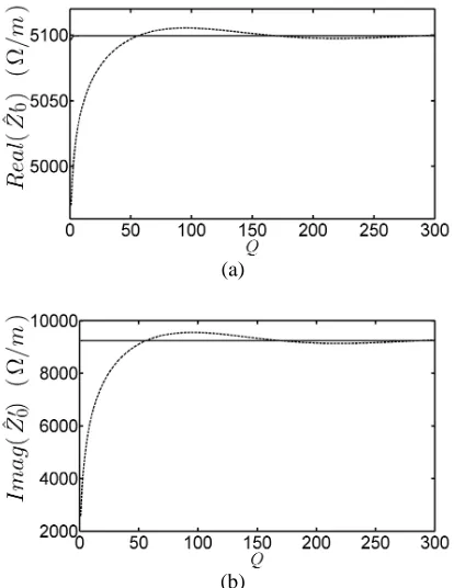
Fig. 5. Convergence of real (a) and imaginary (b) part ofẐ0(=Ẑ0Z0) as the
series limitQincreases. Dashed line:Ẑ0is given by (11). Solid line:Ẑ0is given
by (21).
are truncated, QqQ. Q=200 for (11), but for (21) is considerably lower, Q=10. The accuracy of the simulation results depends on the convergence of the q-series in the Ẑm expressions of (11) and (21). The improved convergence of (21) over that of (11) is demonstrated in Fig. 5 by plotting the value of Ẑ0( =Ẑ0Z0) for different values of the truncated
summation limitQ.
Also shown in Figs. 2-4 are the co-polarization and cross-polarization results obtained using the simple effective transfer impedance expression (25). As indicated in [14], the accuracy of the results of the simple expression improves as the electrical density of the array increases. Since the accuracy of such simple expressions for meshes and patches was considered in [14] and references therein, it is not considered further here. The need for obtaining and improving such simple analytic expressions is emphasized in [14] and references citing it, i.e. they allow physical insight to be applied into the design of devices. This insight leads to a fast and cost effective design process. Subsequently, the accuracy of the results can be improved using tailored electromagnetic methods or commercial software.
V. CONCLUSION
Wait’s free space thin wire entire-domain basis function method of moments was extended to model plane wave scattering from a lumped element periodically loaded vertical narrow strip array backed by a multilayer substrate. The formulation was further modified to improve the convergence of its series term. For a single infinitesimal lumped element per unit cell, novel formulations for the current and the effective
transfer impedance were derived, and, for the case of an electrically dense array on a substrate, a novel simplified expression for the effective transfer impedance was obtained.
REFERENCES
[1] B.A. Munk, Frequency Selective Surfaces: Theory and design, John Wiley and Sons, 2000.
[2] B.A. Munk, Finite Arrays and FSS, John Wiley and Sons, 2003. [3] D. Cavallo, A. Neto, and G. Gerini, “Green's Function Based Equivalent
Circuits for Connected Arrays in Transmission and in Reception,” IEEE Trans. Antennas Propag., vol. 59, no. 5, pp. 1535-1545, 2011.
[4] J.R. Wait, “Theory of scattering from a periodically loaded wire grid,” IEEE Trans. Antennas Propagat., vol. 25, no. 3, pp. 409-413, 1977. [5] D.A. Hill, and J.R. Wait, “Electromagnetic scattering of an arbitrary
plane-wave by a wire mesh with bonded junctions,” Canadian Journal of Physics, vol. 54, no. 4, pp. 353-361, 1976.
[6] C. Mias, and A. Freni, “Application of Wait's Formulation to Connected Array Antennas”, IEEE Antennas Wireless Propag. Lett., vol. 12, pp. 1535-1538, 2013.
[7] C. Mias, and A. Freni, “Generalized Wait-Hill formulation analysis of lumped-element periodically-loaded orthogonal wire grid generic frequency selective surfaces”, Progress in Electromagnetics Research, vol. 143, pp. 47-66, 2013.
[8] R.E. Collin, “Equivalent line current for cylindrical dipole antennas and its asymptotic behaviour”, IEEE Trans. Antennas Propag., vol. 32, no. 2, pp. 200-204, Feb. 1984.
[9] R.E. Collin, Antennas and radiowave propagation, McGraw-Hill, 1985. [10] C.M. Butler, and D.R. Wilton, “General-analysis of narrow strips and
slots”, IEEE Trans. Antennas Propag., vol. 28, no. 21 pp. 42-48, 1980. [11] S. Singh, and D.R. Wilton, “Analysis of an infinite periodic array of slot
radiators with dielectric loading,” IEEE Trans. Antennas Propag., vol. 39, no. 2, pp. 190-196, 1991.
[12] C.M. Butler, “A formulation of the finite-length narrow slot or strip equation,” IEEE Trans. Antennas Propag., vol. 30, no. 6, pp. 1254-1257, 1982.
[13] A.L. VanKoughnett, “Infinite planar and collinear arrays of cylindrical antennas,” Canadian Journal of Physics, vol. 45, pp. 3107-3117, 1967. [14] O. Luukkonen, C. Simovski, G. Granet, G. Goussetis, D. Lioubtchenko,