Evidence for Selective Imaging of Different Magnetic Ions on the Atomic Scale by Using a
Scanning Tunnelling Microscope with a Ferromagnetic Probe Tip
This article has been downloaded from IOPscience. Please scroll down to see the full text article. 1992 Europhys. Lett. 19 141
(http://iopscience.iop.org/0295-5075/19/2/014)
Download details:
IP Address: 134.226.1.229
The article was downloaded on 02/07/2010 at 15:16
Please note that terms and conditions apply.
EUROPHYSICS LETTERS
Europhys. Lett., 19 (2), pp. 141-146 (1992)
15 May 1992
Evidence for Selective Imaging of Different Magnetic Ions
on the Atomic Scale
by
Using a Scanning Tunnelling
Microscope with a Ferromagnetic Probe Tip.
R. WIESEND~NGER (*), I. V. SHVETS (*)
(9,
D.
BURGLER (*), G. TARRACH (*)H.-J.
G~NTHERODT(*) and J. M.D.
COEY(**)(*) University of Basel, Department of Physics Klingelbergstrasse 82, C-4056 Basel, Switzerland
(**) Trinity College, Department of Pure and Applied Physics Dublin-2, Ireland
(received 25 March 1992; accepted 13 April 1992)
PACS. 75.30T - Surface magnetism.
PACS. 61.16D - Electron microscopy determinations (inc. scanning tunnelling microscopy
PACS. 75.25 - Spin arrangements in magnetically ordered materials (neutron studies, etc.). methods).
Abstract. - Atomic resolution has been obtained on a magnetite (Fe30,(001)) surface using a scanning tunnelling microscope with nonmagnetic tungsten and ferromagnetic iron tips. Selective imaging of Fe2 + and Fe3 + on B-sites is achieved by using the ferromagnetic F e probe
tip, reflecting the different spin configurations of the two magnetic ions. Local order in the distribution of Fe2 + and Fe3 + on the (001) surface is found at room temperature, well above the
bulk order-disorder (Venvey) transition.
Magnetic imaging down to the atomic scale is a major challenge for fundamental studies in surface magnetism as well as for advances in magnetic recording. It is well known that the scanning tunnelling microscope (STM) can routinely provide atomic resolution on surfaces of conducting samples. Attempts to combine the high-resolution capability of the STM with some kind of spin analysis to probe magnetic surface structures down to the nanometer scale have recently been reported. For instance, a direct observation of the precession of individual paramagnetic spins on oxidized silicon surfaces in a constant magnetic field has been made where the Larmor frequency signal was shown to be localized over distances less than one nanometer [l]. Vacuum tunnelling of spin-polarized electrons was first observed in STM experiments using a ferromagnetic CrOB tip and a Cr(001) test surface [2,31. That experiment distinguished the alternatively magnetized terraces of the Cr(001) surface on a nanometer scale and yielded the local effective polarization of the tunnel junction. In this
142
U )
EUROPHYSICS LETTERS
b )
Ca
k
octahedral interstices tetrahedral interstices 0 02-ions
Fig. 1. - a) Crystal structure of magnetite with tetrahedrally co-ordinated A-sites (Fe3+) and
octahedrally co-ordinated B-sites (Fe2+ and Fe3+). The C, and Cb planes are shown in b ) and c),
respectively, with an ordering of Fe2 + and Fe3 + according to a model [ 101 for the low-temperature
phase of magnetite.
letter, we report the first selective imaging of different magnetic ions on the atomic level.
Our success is based on the ability to obtain atomic resolution in STM on ferromagnetic samples by using ferromagnetic probe tips prepared
in situ.
Magnetite (Fe3 04), the best-known natural magnetic mineral, has played a key role in the discovery and development of magnetism. Here it has been chosen as a test sample for several reasons. Firstly, it is a transition metal oxide with a room temperature conductivity of about 100 (R em)-' which is high enough to allow for STM investigations. Secondly, on the basis of band structure calculations [4], magnetite is theoretically predicted to be a half-metallic ferromagnet promising a high degree of spin polarization of the electronic states near the Fermi level, very similar to the case of CrO' which was successfully used in our earlier spin-polarized tunnelling studies [2,3]. Thirdly, magnetite as a ferrite (Curie temperature 860 K) provides a unique model system for magnetic-sensitive STM investigations on the atomic scale because its relatively complicated spinel-type structure (fig. l a ) ) with many structural different crystal planes with different magnetization directions and inequivalent sites as well as different ionic species (Fe' +
,
Fe3 +,
O2 - ) allowsfor a rich variety of STM studies.
We have used natural single crystals of magnetite from Austria (Zillertal) which were carefully characterized by X-ray diffraction and electrical-resistivity measurements as a function of temperature. The Venvey transition which is very sensitive to the sample stoichiometry [51 was at 98 K. Several different methods for preparing the (001) surface of magnetite were tried.
In situ
cleavage of the bulk crystal in an ultrahigh vacuum (UHV) [image:3.481.66.421.68.307.2]R. WIESENDANGER et al.: EVIDENCE FOR SELECTIVE IMAGING OF DIFFERENT ETC. 143
rough on the nanometer scale and therefore unsuited for atomic-resolution STM studies.
Consequently, we tried mechanical polishing followed by
in situ
annealing up to about (1000 2 50) K. This preparation procedure also resulted in clean surfaces as checked by AESbut the surface roughness was considerably reduced compared with the cleavage procedure. We were therefore able to reproducibly obtain high-quality low-energy electron diffraction (LEED) patterns as well as atomic resolution STM data on the Fe3 O4 (001) surface which are consistent with a nonreconstructed surface structure. The annealing treatment did not affect the stoichiometry and atomic structure at the magnetite surface as checked by AES, X-ray photoelectron spectroscopy ( X P S ) , LEED and STM.
For nonmagnetic STM studies of the Fe304(001) surface we used conventional W tips prepared by electrochemical etching of a 0.25 mm diameter W wire. Magnetic-sensitive STM studies were performed with atomically clean and sharp ferromagnetic F e probe tips which were prepared
in situ
in UHV (1 * lo-" mbar) [6]. The atomic-resolution capability of the Wand Fe tips were tested on the well-known Si(OO1) 2 x 1 surface prior to the investigations of the Fe304(001) surface. All experiments were performed at room temperature in a multichamber UHV system (Nanolab) with several surface preparation and analysis facilities and a base pressure a t least in the low 10-"mbar range [7]. The STM has a proven stability
at the tenth picometer level as tested on the Si(OO1)Z x 1 surface. All STM studies were performed with a positive sample bias voltage probing the empty states of the Fe3 O4 (001) surface. A bias voltage of at least 1 V was needed to get a stable tunnelling current of 1 nA.
This observation is consistent with recent inverse photoemission data obtained on
in situ
cl'eaved Fe3 04, showing a low density of states directly at the Fermi level and an increase towards 1 eV above the Fermi level [8].
The STM images obtained on the Fe3 O4 (001) surface using either W or Fe tips reveal two different topographies. The first kind of topography shows terraces mostly separated by 4.2
A
high steps which correspond to half of the unit cell height (fig. la)). The right angles always observed reflect the symmetry of the (001) surface of magnetite. Atomic-resolution images obtained on top of these terraces reveal a periodic square lattice corresponding to the top (001) plane of the crystal structure shown in fig. la) which is built up only by the tetrahedrally co-ordinated A-sites of the spinel structure, occupied by Fe3 +
.
Theseobservations will be discussed elsewhere [9].
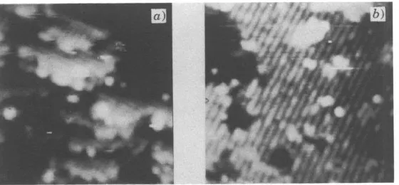
Fig. 2. - a) STM image ((155 x 165)
A2)
of the C, and C, planes of magnetite obtained with a W tip. The observed terraces are separated by 2A
high steps. The atomic rows seen on top of the terraces have a spacing of 6A
and change their orientation by 90" from one terrace to the next. They must be interpreted as the F e rows (B-sites) in the Fe-0 lanes. (Tunnelling current: Z = 1 nA, sample bias voltage [image:4.480.98.378.444.574.2]144 EUROPHYSICS LETTERS
The second kind of topography of the Fe3
O4
(001) surface as imaged both with W and F e tips is shown in fig. 2 a ) and b). Again, terraces are observed which now are separated by about 2 A high steps. On top of these terraces, atomic rows can be seen which change their orientation by 90" from one terrace t o the next. The spacing between these rows is about 6A
asmeasured with both W and Fe tips (fig. 3a)). These atomic rows seen in the STM images can only be interpreted by the rows of octahedrally co-ordinated B-sites which are occupied by both Fe2+ and Fe3+ in the (001) crystal planes of magnetite built up by Fe and 0. The separation between these planes is indeed 2 b and the orientation of the rows of Fe sites changes by 90" from one plane to the next as shown in fig. l b ) and c). Notice that the separation between the rows of 0 sites would only be 3
A.
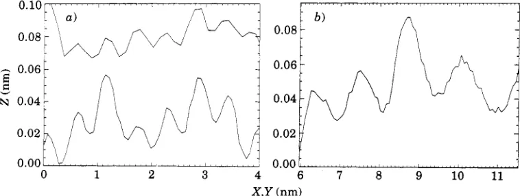
The selective imaging of Fe sites with both W and Fe tips is a spectroscopic effect which can be explained by a dominance of tunnelling via the empty Fe 3d states compared with the 0 2p states.Differences between the experimental results obtained with the W and Fe tips can be found from a closer inspection of the measured corrugation perpendicular and along the rows of B sites. Based on a statistics of several hundred line scans perpendicular to the rows of Fe sites, we have found that the corrugation amplitudes as measured with the ferromagnetic Fe tips are typically by a factor of 2-3 higher than those measured with a nonmagnetic W tip (see fig. 3 a ) ) . This is already a hint for an additional magnetic contrast mechanism although it is not yet a direct experimental proof, since it could be argued that measured corrugation amplitudes will depend on the sharpness of the tips and the orbitals in front of the tip through which the tunnelling current is flowing.
The direct proof for a magnetic contrast mechanism in the STM images obtained with the ferromagnetic Fe tips is based on the analysis of line sections along the rows of Fe sites. The corrugation All(W) along the Fe rows as measured with W tips has always been found to be much less than the corrugation A
,
(W) perpendicular to the Fe rows. All0
was typically of the order of 0.1A
or below which corresponds to the noise level in these experiments. No periodic corrugation has yet been observed along the Fe rows when a W tip is used. The separation of only 3 A between the F e sites along the Fe rows leads to a small corrugation amplitude with a periodicity of 3A
which is unresolved. In contrast, the corrugation All (Fe) along the Fe rows as measured with an Fe tip has been found to be at least as high as the corrugation A , (Fe) perpendicular t o the Fe rows, sometimes even higher by a factor of 2 (fig. 3b)). Comparison of measured corrugation amplitudes in different STM images obtained with different tips is not very meaningful. However, the comparison of the ratio A,, / A , as0 1 2 3 4
0.08
0.06
0.04
0.02
0.00
6 7 8 9 10 11
X,Y (nm)
Fig. 3. - a) Corrugation perpendicular to the F e rows (B-sites) as measured with a W (top) and F e tip (bottom). The observed periodicity is 6
A
in both cases. The corrugation amplitude is typically higher when using an F e tip. b ) Corrugation along the F e rows (B-sites) as measured with an F e tip. A [image:5.480.56.435.464.607.2]R. WIESENDANGER et al.: EVIDENCE FOR SELECTIVE IMAGING OF DIFFERENT ETC. 145
Fig. 4. - a) High-resolution STM image obtained with an Fe tip showing the F e rows (B-sites) with the 6
A
spacing and a clear modulation along these rows. The 12A
period is preferentially observed and highly reproducible as shown in the successive STM image in b). A new maximum (marked by an arrow) appears in b) which fits into the observed 12 Aperiodicity. The total grey scale corresponds to about 1A
for both images. (I = 1 nA, U =+
3.0 V.)determined from one single STM image is significant. Our experimental results can be summarized by All (Fe)/A I (Fe) b 1, whereas All O / A I
0
<<
1.Even more interesting, we have found a periodicity of 12
A
along the F e rows only in the &ase when a ferromagnetic F e probe tip is used (fig. 3b)). This periodicity corresponds to four times the spacing of 3A
between the F e sites along the F e rows. The observation of this 12A
periodicity can only be explained by a corresponding repeat pattern of Fe2 + and Fe3 + ionsalong the F e rows as has already been proposed for the low-temperature phase of Fe304 below the Verwey transition[lO-121 (fig. l b ) and c)). The observed magnetic contrast is attributed to the difference in the spin configuration which is 3d5 T 3d 1 for Fe2 + and 3d5
'
forFe3 +
.
In fig. 4a) and b) we present two high-resolution STM images of the same region on theFe304(001) surface obtained with a ferromagnetic Fe probe tip which also show the 12A periodicity along the F e rows. Notice the high degree of reproducibility of the positions as well as the intensity of the observed maxima along the F e rows. The observed intensity of
the maxima may be at least partially determined by the alignment of the individual magnetic moments of the Fe ions which can sometimes change from one image to the next as a result of
magnetic tip-surface interaction, as also observed in fig. 4a) and b) (marked by an arrow).
It
is also evident from our data that the 12
A
periodicity is only observed over distances of several nanometers, showing that there is medium-range order in the spatial distribution of Fe2+ and Fe3 + ions on B- sites in the (001) surface at room temperature. The 3d 1 electrons on thesurface appear to form a <<Wigner glass., whereas those in the bulk hop rapidly among B-sites. An explanation may be that these electrons form a narrow band derived from d,,
orbitals at the surface, which is split off from the other
t,
bands by the lowered symmetry.In summary, the first atomic resolution STM study of a ferromagnetic surface with a ferromagnetic probe tip has been performed. Magnetic contrast at the atomic level is observed on the Fe3 O4 (001) surface with an F e probe tip resulting from a selective imaging of the different ions Fe2 + and Fe3 + with their different magnetic moments. Spin-polarized
[image:6.480.83.374.57.189.2]146 EUROPHYSICS LETTERS
of the magnetic ions present at the sample surface and the tip. It is expected that a combination of the ability of magnetic reading at the atomic level, as demonstrated in this letter, with the ability to write on the atomic scale[13] will lead to the first prototype magnetic storage devices of atomic-scale dimensions.
* * *
We would like to thank Prof. S. G R ~ E R for kindly providing natural single crystals of magnetite, as well as Profs. R. A. DE GROOT and G. GUNTHERODT, Dr. V. HOFFMANN, Profs. A. HUBERT and H. THOW for stimulating discussions. Financial support from the Swiss
National Science Foundation is gratefully acknowledged.
R E F E R E N C E S
[l] WASSEN Y., HAMERS R. J., DEMUTH J. E. and CASTELLANO jr. A. J., Phys. Rev. Lett., 62 (1989)
[2] WIESENDANGER R., GUNTHERODT H.-J., GUNTHERODT G., GAMBINO R. J. and RUF R., Phys. Rev.
[3] WIESENDANGER R., BURGLER D., TARRACH G., WADAS A., BRODBECK D., GUNTHERODT H.-J.,
[4] YANASE A. and SIRATORI K., J. Phys. Soc. Jpn., 53 (1984) 312.
[5] ARAGON R., BUTTREY D. J., SHEPHERD J. P. and HONIG J. M., Phys. Rev. B, 31 (1985)
161 WIESENDANGER R., BURGLER D., TARRACH G., SCHAUB T., HARTMANN U., GUNTHERODT H.-J.,
[71 WIESENDANGER R., TARRACH G., BURGLER D., JUNG T., ENG L. and GUNTHERODT H.-J.,
[81 SANCROTTI M., CICCACCI F., FINAZZI M., VESCOVO E. and ALVARADO
S.
F., 2. Phys. B, 84 (1991)I91 WIESENDANGER R., SHVETS I. V., BURGLER D., TARRACH G., GUNTHERODT H.-J. and COEY J. M.
[lo] IIDA S., MIZUSHIMA K., MIZOGUCHI M., KOSE K., KATO K., YANAI K., GOTO N. and YUMOTO S., J.
[ll] IIDA S., MIZOGUCHI M., GOTO N. and MOTOMURA Y., J. Mugn. & Magn. Mater., 31-34 (1983)
[12] KITA E., TOKUYAMA Y., TA~AKI A. and SIRATORI K., J. Mugn. & Mugn. Mater., 31-34 (1983)
[13] EIGLER D. M. and SCHWEIZER E. K., Nature, 344 (1990) 524.
253 1.
Lett., 65 (1990) 247.
GUNTHERODT G., GAMBINO R. J. and RUF R., J. Vac. Sci. Technol. B, 9 (1991) 519.
430.
SHVETS I. V. and COEY J. M. D., Appl. Phys. A, 53 (1991) 349.
Vacuum, 41 (1990) 386.
243.
D., Ultramicroscopy, in press.
Appl. Phys., 53 (1982) 2164.
771.