Abstract—3D printing is well established for macro dimension 3D Printing. The feasibility of 3D Printing for a water quality sensor with 10 nm and 100 nm layers and a printing area of 1.4 cm by 1.4 cm is considered. The process of 3D Printing requires relative motion of the extruder with respect to the print bed. Servo motors are not suitable as they lack the ability to hold the shaft stationary without an external brake. The stepper motor does not need high end feedback systems for positioning. The Hybrid Stepper Motors with 1/128 or 1/256 micro stepping do not provide adequate accuracy. Piezo walk motors provide high moving and holding force and resolution in picometer range. A Hybrid Stepper Motor can provide coarse positioning and the piezo walk motor can provide fine positioning.
Index Terms— 3D printer, piezo electric motor, nano resolution, stepping
I. INTRODUCTION
The stepper motors are the most common type of actuators used in 3D printers [1]. Ease of use and high precision without the need for high end feedback sensors make them suitable for 3D printing. Unlike standard electric motors, these motors do not rotate continuously, but move in a step-by-step fashion. To drive a stepper motor, a stepper motor driver is required.
3D Printers use four stepper motors – one for each of the three axes and one for the extruder. Most of the stepper motors have a step angle of 1.80 . 1.80 step angle per full step is a commonly used step rating and is equivalent to 200 steps per revolution [32]. Some 3D printers use larger step angle motors for higher speed, whereas for accurate printing, a lower step angle is needed. But this can lower the speed of operation.
Manuscript received July 05, 2016; revised July 30, 2016. This work is performed in BITS PILANI DUBAI CAMPUS, Dubai as part of Arivarasi‟s Doctoral Research and Shamith‟s undergraduate project.
Shamith Louis Saldanha is an undergraduate engineering student of (Electrical & Electronics Engineering) BITS PILANI DUBAI CAMPUS, Dubai. P.O BOX 345055 Phone +971 04 420 0700 email [email protected]
Arivarasi A is the PhD student of (Electrical & Electronics Engineering) BITS PILANI DUBAI CAMPUS, Academic city, Dubai. P.O. BOX 345055 Phone +971 04 420 0700 email [email protected]
Dr Anand Kumar, Professor - Electrical & Electronics Department is with BITS PILANI DUBAI CAMPUS, Dubai. P.O.BOX 345055 Phone +971 04 420 0700 email [email protected]
Servo motors are not suitable for 3D printer as they do not have the ability to hold the shaft stationary without the use of an external brake. Stepper motors have the ability to hold the rotor shaft in place without needing special brakes or circuitry. In other words, the motor torque while stationary, called holding torque, is high. Stopping the stepper also does not create back-emf spikes as much as in regular motors. Also, servo motors rotate continuously when power is applied [21]. The stepper motors rotate in discrete steps, which means that the angular position of the shaft, when using the stepper can be counted from a known reference point without any feedback. Any error in the position of a stepper does not accumulate with every step taken and this increases predictability of the steps taken. Servos require encoders and sensors to communicate the angular position of the shaft to the control unit. This extra equipment increases the cost of the servos to more than 2 to 5 times of steppers of comparable performance. Using standard microcontrollers and steppers can give a precision of less than a 100 micro meters. For these reasons, stepper motors are chosen for many precision motion control applications, including 3D printers [1].
Since the stepper motor moves in precise repeatable steps, they could be used in applications like CNC, Camera platforms, X-Y plotters and 3D printers. Disk drives use stepper motors for read-write head positioning. Precise increments of movements enable good control of rotational speed for robotics and process automation. At low speeds, normal DC motors do not provide much torque. However, stepper motors provide high torque at low speeds. Hence they are suitable choice for applications with high resolution.
There are drawbacks to stepper motors. The stepper motors‟ power consumption is independent of load. They draw high current, even when idle. They tend to become hot under these conditions. Appropriate drivers are required to achieve high torque at slightly higher speeds. For higher speed optimization, stepper motors need to be paired with a suitable driver. Unlike servo motors, steppers do not need feedback for positioning [22]. Good positioning is achieved in open loop operation but closed loop steppers are often used. But limit switches or home detectors are typically required for safety and to establish a reference position. Different types of steppers are available – variable reluctance steppers, permanent magnets and hybrid steppers. In the design of 3D printer for the printing of sensors, hybrid steppers are selected. Steppers could be either 2 phase bipolar or 4 phase unipolar [7]; linear versions of the these also exist, but are not common. Rotating steppers linked with gears and screws to get linear motion is selected. Electromagnetic stepper motors are used for 3D printing. But to meet the requirements of micro/nano scale 3D
Design of a Stepper Motor for Nano Resolution
3D Printing
printing, the micro stepping and in particular piezo electric motors are explored.
II. STRUCTURE OF NANO SENSOR LAYERS
The structure of the water quality sensor that detects the presence of heavy metal ions that is to be 3D printed is discussed. The electrode is made of nanoporous gold. Nanoporous gold has high electrical conductivity and high surface to volume ratio enabling self assembled mono layer formation [36]. PGC based plating solution is used to form nanoporous gold. The sensor layers for 3D printing includes a base substrate; silicon is a suitable material for this substrate. The substrate with dimensions of 1.4cmx1.4 cm is used. A Titanium adhesive layer of thickness 10 nm is used to hold the substrate below and Copper layer of thickness 100 nm above. The process of 3D printing the sensor includes printing the Titanium on the Silicon substrate followed by printing the Copper on top of the Titanium. The printing of copper includes sintering at 70-80ºC. Then, alkaline Potassium Gold Cyanide (PGC) is sprayed using 3D printer nozzle. Chemical reaction between Copper and PGC in this electroless plating technique results in the formation of Nano Porous Gold Film (NPGF) on the surface. A stepper motor is required to move the extruder with respect to the bed during the different processes and steps of 3D printing the sensor. The layers are 10 nm and 100 nm thick implying nano scale resolution [36]. The sensor layers are 3D printed in nanometer resolutions and hence used for detecting heavy metal ions in water [36].
III. SELECTING A STEPPER AND DRIVER
Motor and controller specification are key to determining suitability for micro/nano 3D printing. Most motors have torque specifications either in ounce-inches or in newtons centimeter (N-cm). The material weight applied to the printer determines the specific instant torque. The motor and selection criteria are determined by the motor features like output power and torque rating, pull-in and pull-out torques, noise thresholds, losses involved [37].
Motor is specified in terms of current per phase, Resistance per phase and voltage rating per phase. Amps per phase is the maximum current that the motor windings can handle without overheating. Resistance per phase is the resistance for each phase. Voltage rating can be calculated from these two. Stepper motor phases are inductors which resist rapid changes in current flow. At the end of each step, they behave like a purely resistive load according to ohm‟s law rule V=IR.For a “constant voltage” steppers, the drive voltage will be less, resulting in poor performances. In this case, a specialized driver is a must. Torque rating is also to be considered.
The size of the motor is indicated by its NEMA number, which indicates the length of its faceplate. The NEMA number is the length or diameter in inches multiplied by 10.Larger motors can deliver more power and require more current and a larger driver. Stepper motors are available in a range of sizes. NEMA 17 is commonly used for 3D printers. Very small motors are used in robotics and animation systems. Larger motors are used in industrial and CNC machines. NEMA 17 motor has a diameter of 1.7 inches. For a square shaped NEMA 17 motor, the length of side is
1.7”. The NEMA number also specifies the mount type code, length, phase current, insulation class, maximum allowable operating temperature, phase voltage, steps per revolution, and the type of winding code. NEMA DDMMLLL-CCCIVVVSSSW is the full NEMA description. DD denotes diameter in inches, MM is the mount code, LLL is length, CCC is phase current, I is insulation class, VVV is phase voltage, SSS steps per revolution and W is a winding code. For example, NEMA34D018-012A053200F indicates that the stepper motor has 3.4” diameter with a flange of 1.8 inches long, has 1.2 amps phase current, Class A insulation, 5.3 phase voltage, 200 steps per revolution.
The step count per revolution specifies the positioning resolution. The number of steps per revolution ranges from 4 to 400. 24,48 and 200 are commonly used step counts.Resolution is the total angle of a revolution (i.e., 360 degrees) divided by the step count per revolution. Resolution is expressed in degrees per step. Standard steppers used in 3D Printers have a resolution of 1.8 or 9 degrees per step.There is a trade-off between speed and torque, in terms of resolution, and degrees rotated per pulse [31].
A step-down gear train increases the torque of the motor and decreases the distance/angle travelled per step but this reduces speed. A modified step rated motor is obtained using gear train (having a gearing ratio) applied to the output of a motor. To interface with rest of the drive system, the shaft styles are provided, which could be one of the following (1) Round or “D” shaft (2) Geared shaft (3) Lead screw shaft. The second and the third have the rotary-to-linear motion converter inbuilt, and also increase torque and resolution.
The coils of a stepper are arranged in phases. Steppers are available commonly as 2- or 3-phases, although 5-phases are also seen. Unipolar and Bipolar circuitry are the two controlling circuits primarily used in steppers.
Stepper motors available in different models differ by their internal connections. A unipolar drive circuitry can have either 5, 6 or 8 leads [38]. There is a need of current limiting resistor between the windings and power supply. Unipolar circuitry works with two separate field coils and has changeover switch. Bipolar circuitry has one field coil and two changeover switches that are switching in opposite direction [42].
The controlling circuitry should enable flow of current in both directions. It should start and stop current within the winding as required. In unipolar circuitry [38], there is a center tap to each phase winding. The center taps are usually connected to the positive power supply, whereas the two ends of each winding are grounded through the control circuitry. Unipolar drivers energize the phases in the same way. Half of the coils are energized at a time.
energized. BM requires complex driving circuitry with more transistors and thereby increasing cost. Most of the commercial 3D printers have bipolar windings.For general operation one can use the DRV8812 [10] or the DRV8825 [11]. These are driver ICs from TI are particularly suited to standard Hybrid Stepper Motors(HSM) used in 3D printing applications. Some motors come with flexible wiring, that enables them to operate either in bipolar or unipolar mode. For example, a 2-phase stepper motor with flexible wiring can operate in 4 phase unipolar, 2 phase parallel bipolar or 2 phase series bipolar modes. In the 2 phase parallel bipolar mode, the phases are connected in parallel. This implies half the resistance and inductance, but double the current. Higher torques and speeds are achieved. Stepper motors require a stepper controller to energize the phases in a time sequence to run the motor. Simple unipolar drivers are used with unipolar motors. An example is the DRV8805 from TI. An example of Simple bipolar driver includes the DRV8825 mentioned earlier. L293D, a motor driver IC, can also be used.
The maximum voltage and current that the driver can supply to the motor are key driver specifications. Continuous current rating, rather than peak current ratings are more important in stepper motors as these motors hold the shaft stationary for a relatively long time and require constant current to maintain that torque.
Three modes of stepping are usually used in stepper motors. These modes are the wave, full-step and the half-step. Each require somewhat different driving circuitry. A fourth stepping mode known as, micro stepping can greatly improve resolution of printing in 3D printers. For accuracy using this method, the torque and magnetic field versus position curve may also need to be known [25].
Wave stepping provides resolution determined by the construction of the motor. Only one phase is switched on at a time. Full stepping provides more torque, requires more current, and hence consumes more power. Here two phases are switched on in sequence at the same time. However, the resolution of full stepping is comparable to that of wave mode stepping.
In Half Stepping 1 phase and 2 phases are switched on alternatively. Therefore, this method doubles the resolution of the motor, however the torque for each step is not equal as 1 or 2 phases are activated at a time.
Current plots drawn by the unipolar motor with 4 coils driven by wave drive, full step drive, half step drive and micro step modes have been previously simulated [40]. Micro steppers can be used to obtain micro/nano-scale movement. Micro stepping is a way of moving the rotor of the stepper motor, in such a way that it moves in steps, smaller than that possible, due to the organization and design of the stator and rotor [15]. Therefore, if a standard HSM has an inbuilt minimum step angle of 1.8 degrees, a 1/16 micro stepping driver (common in the market) will give a minimum step angle of 405 arc seconds or 0.11 degrees. When used with step-down gears, pulleys and screws, it is possible to get sub-micro meter range in the hundreds of nm, though not in the 1 nm range.
Micro stepping, such as 1/128 or 1/256 micro stepping does not provide accuracy, and is generally not used [16]. Micro stepping is also used to move the stepper through full or half steps more smoothly, as the current varies continuously rather than in steps. It creates less vibration inand stress on the shaft.
In an ideal HSM, torque varies sinusoidally with shaft angle. In commercial steppers, torque-shaft angle plot will deviate from the pure sinusoid. However, in many modern steppers, the deviation is small. The drives are sophisticated. But, there are inaccuracies in position. There is always static friction, known as stiction. Stiction between two surfaces opposes an applied force, thereby causing the object to remain stationary [41]. The object remains stationary until the applied force exceeds force of stiction 𝑓𝑠𝑡𝑖𝑐𝑡𝑖𝑜𝑛 [39].It can be shown as in equation (1).
𝑓𝑠𝑡𝑖𝑐𝑡𝑖𝑜𝑛 ≤ 𝜇ℛ - (1) where R= normal force on the surface in Newtons. μ is the coefficient of static friction. This force of stiction, or otherwise called torque of stiction nullifies torque and creates dead zones within the torque position curve, as well as reducing the total static torque available for the load. The incremental torque for N microsteps is given by
𝑇𝑖𝑛𝑐𝑟𝑒𝑚𝑒𝑛𝑡𝑎𝑙 = 𝑇𝑜𝑙𝑑𝑖𝑛𝑔 sin(90 ∗ 𝑁/𝜇)- (2)
where𝑇𝑖𝑛𝑐𝑟𝑒𝑚𝑒𝑛𝑡𝑎𝑙 = Incremental torque for N microsteps,
𝑇𝑜𝑙𝑑𝑖𝑛𝑔 = Rated Holding torque, 𝜇 = Number of microsteps per full step, N = Number of microsteps taken [15]. Holding torque is the amount of torque the motor produces, when the motor is at rest and rated current flows through the windings. If this incremental torque produced during microstepping is quite small, and if it is less than the static friction, the rotor will not move as per equation (2). To reduce friction during microstepping process, magnetic floats can be used as in a maglev train. However, magnetic floats can only be used in high speed vehicles like trains to be cost-effective. To use them in 3D printers, a higher power input is required. Furthermore, a well-designed control system for maintaining the stability of the motor is needed. Such a system would dramatically increase the cost of the system. Therefore, magnetic floats may not be appropriate for 3D printing.
Micro stepping can be done by interfacing microcontrollers with a motor driver, or by using a specialized micro stepping driver. TI microcontroller MSP430F1612 can be interfaced to motor drivers [12] like DRV8812 [10] or DRV8825 [11]. Dedicated micro stepping driver can be used without a microcontroller. One example of this drive is A3977[13] from Allegro Microsystems. When a microcontroller is interfaced to the drive, there is greater flexibility, but requires greater set up complexity. To decide the correct method of micro stepping, the resolutions are compared. The resolution is 0.0005” for 1/8 stepping mode and 0.0002” for 1/16 steps. The resonance or acceleration is worse for 1/8 stepping. The print quality will be noticeably worse. It would be best to keep the micro stepping range to 16 micro steps per full step. This is the highest possible resolution for micro stepping.
IV. 3D PRINTING CONSIDERATIONS FOR NANO SCALE RESOLUTION SENSOR
1. The travel ranges and direction of the nozzle 2. Weight of the extruder
3. The direction of print bed movement
The nano sensor 3D printing involves the printing of viscous liquids in the nanometer scales on the print bed. Therefore, any movement of the print bed in the x and y directions can cause movement of the liquids and affect the accuracy of printing. For nanoscale requirements, the print bed is to remain stationary with respect to the x and y directions. Further the print bed should be shielded from the vibrations and movements of the extruder and its attached parts.
The movement in z-direction is sporadic and is not periodic. The print bed is likely to be of relatively heavier compared to that of the extruder set up. The proposed design couples the standard hybrid stepperto an accurate lead screw through step-down gears. The step-down gears would multiply torque, reduce the velocity, and reduce the acceleration. This wouldreduce the vibrations to the material. The material would be printed uniformly. It would be beneficial to add a micro stepping driver to the z-axis stepper motor. It would improve the resolution of the motor. More importantly, it would allow for smooth movement of the z-axis, so asto reduce small vibrations and ensure uniform printing.
Based on the design dimensions, print bed size and heating requirements, the nozzle travel limits are decided. Since the z-direction movement is achieved by the print bed, the extruder and related equipment do not have to move vertically. The x-axis and the y-axis movements would each require a stepper motor. The stepper motors would have to be connected to gears to multiply torque and decrease travel distance, to improve the resolution. The gears are then connected either to a timing belt or a lead screw to the extruder. However, the extruder is supported on two linear rods either through bushings or bearings. Bushings are oil-infused brass hollow cylinders that grip the support shaft. Bearings are similar in size. Ball bearings are used to minimize friction. Bearings are costlier, but with less friction. However, the difference between them is not much, and the choice is quite arbitrary.
The stepper motors used in 3D Printers have different loads. The x-axis and the y-axis stepper motors need to move the extruder pack along a smooth rod, through gears and timing belts. These motors will have to ensure continuous and fast movements.
The timing belt is connected between the running pulley and an idler pulley. A common example of such a belt is the GT2 timing belt [7]. For the nano scale 3D printing of sensor layers, considering the short and minute travel range and the need for very precise movements, lead screws could be used for the X and Yaxes. Timing belt is a toothed belt used with toothed pulleys to transfer motion and power in tiny motions control [40]. In abnormal conditions like generation of noise due to wear, the idler pulley accounts for most of the failures due to tension. Misalignment of the timing belt could cause premature failure of idler pulley and belt [43].
There is a greater load on the z-axis of the printer, but its movements are comparatively lesser than in the x and yaxes. Hence the steppers are chosen based on calculated load. A standard extruder for 3D printing applications (the MK8)
from Geeetech [3] weighs approximately 450 g. A maximum of double that weight (i.e. 1000 g) could be considered for the mass of the extruder formicro/nano printing.
V. APPLICATION OF PIEZO ELECTRIC STEPPER MOTOR TO 3D PRINTERS
The options available are increased by considering another kind of motor called the piezo-electric motor. This motor is an ingenious application of the piezoelectric effect. These motors do not have any magnetic parts, and offer higher force and nanometer resolution, as compared to the traditional steppers. However, there are associated cost and operational limitations with these kinds of motors.
Piezo electric effect: Piezoelectric materials generate electrical charge in response to applied mechanical stress [2]. These materials also convert electrical energy into mechanical motion directly and this is known as the inverse piezoelectric effect [2]. The mechanical compression and expansion caused by an electric voltage is used in piezoelectric motors. They are used in high precision applications such as manufacturing, astronomy, optics, surgery etc.
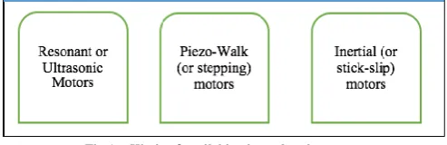
[image:4.595.305.552.448.528.2]Types and applicability: Piezo drives can be divided into actuators and motors [16]. Actuators have maximum travel range from a few micro meters to 100-200 micro meters, whereas motors have longer ranges up to 10 mm. Three different kind of piezo-electric motors [2] are described in Fig 1. Ultrasonic resonance motors are fast, compact and quiet [16], and are the most widely studied piezo-motors. But, they have a low holding force, and produce steps in the order of 50 nm [16, 17].
Fig 1 – Kinds of available piezo electric motor
Piezo walk motor is most complex in construction. They use piezo ceramic legs in different phases that push a runner rod in a clamp – move–release fashion. Piezo walk motors have the highest force (both moving and holding), and give the best resolution (often in the picometer range) [16], but have low speeds and have a higher cost. The highest resolution and force of the piezo walk motor makes it attractive for applications involving nano scale movements. Inertial motors run on the slip effect [16]. The stick-slip motors have lowest cost and are very compact, having relatively high holding force. However, resolution is not as good as compared to the piezo walk motor.
Piezo motors are well suited to operate in clean rooms. As the crystal and support structure is enough to generate the required movement, it is possible to miniaturize these motors without significant loss in efficiency or power-to-weight ratio. These miniaturized motors can be used to move the nozzle in 3D printer equipment, in nanometer steps. The complexity of the motor drive and therefore the cost is higher. The cost of manufacturing these small crystals required in the piezo motors is high. The cost of a standard NEMA 17 motor is around $40-$100. The cost of a piezo motor is more than $500. Furthermore, higher voltages in the order of 100s of volts are needed requiring specialized and costly drivers. Another disadvantage is that the geometry size change of a piezo crystal with electrical input is not identical, and varies with the load. Accuracy depends on the load factor. In 3D printing, the dynamic load of the supplied material will affect printing accuracy. There is a lack of complete precision in the manufacture of gears, belts, pulleys, causing backlash, in practical conditions. Due to the inevitable presence of friction in these devices, there is a possible limit to the resolution of the extruder movement. The HSM cannot be operated below a micro step size. With precision and anti-backlash gears, and use of lead screws instead of the belt-and-pulley system, and with the use of microstepping, a resolution in the range of a few hundred nanometers can be achieved. So it is proposed that we try to build a system to get a resolution in micro / nano meters, and make sure it is accurate. 3D printing of sensors requires better resolution. A small piezo-walk motor, as lightweight as possible, is added to the extruder, in addition to the nozzles and machinery already present. The HSMs provide a sort of coarse positioning, whereas the piezo stepper provides fine positioning to within a few nm. For the piezo-device connected to the nozzle, an x- y positioner could be used, and this piezo-device has a capability to move in both directions. QNP-50- 250XYfrom Aerotech [18] is an example of such a device. It has an open loop resolution of 0.50 nm and a travel range of 250 micro meter. It weighs more than 170 g. It can be added to the extruder (weighing 500 g to 1 kg) with little difficulty. Another choice is to put two lightweight piezo-walk motors: the LL1011D from PiezoMotor Uppsala AB, Sweden. It has a resolution of 1nm. It weighs 23 g, and requires a maximum of 48 V and requires a micro stepping driver(s) like one PMD206 or two PMD101.
VI. CONCLUSION
3D printing is well established for macro dimension 3D Printing. The feasibility of 3D Printing for a water quality sensor with 10 nm and 100 nm layers and a printing area of 1.4 cm by 1.4 cm is considered. This water quality sensor detects the presence of heavy metal ions in water. The process includes layering Titanium and Copper in sequence on Silicon substrate. The copper is sintered. This is followed by spraying PGC on the Copper layer resulting in a chemical reaction and formation of NPGF. This NPGF detects the presence of heavy metal ions.
The process of 3D Printing requires relative motion of the extruder with respect to the print bed. Servo motors are not suitable as they lack the ability to hold the shaft stationary without an external brake. The stepper motor provides do not need of high end feedback systems for positioning. The stepper motor in micro stepping mode provides better
resolution than wave stepping, full stepping or half stepping modes. Bipolar windings are common in Hybrid Steppers. The Hybrid Stepper Motors with 1/128 or 1/256 micro stepping do not provide adequate accuracy. Piezo walk motors provide high moving and holding force and resolution in picometer range. The high force is necessary to overcome the stiction force. A Hybrid Stepper Motor can provide coarse positioning and the piezo walk motor can provide fine positioning.
The stepper motor specifications are determined by the travel ranges and directions of the nozzle, and the weight of the extruder. It is proposed that the print bed remain stationary while the extruder movers in x, y, and z directions. Finally, it is proposed that a 3D-printer be built such that the HSMs move the extruder and provide coarse positioning, whereas the piezoelectric motors (or x-y positioning stages) provide fine positioning to get the required nanometer resolution.
REFERENCES
[1] Young, Julie, and Ilse Blansert. Idiot's Guides: ASMR. Penguin, 2015.
[2] Spanner, Karl, and Burhanettin Koc. "Piezoelectric Motors, an Overview." Actuators. Vol. 5. No. 1. Multidisciplinary Digital Publishing Institute, 2016.
[3] “Details On Geetech upgraded single head MK8 Extruder”, available : http://www.geeetech.com/wiki/index.php/MK8_Extruder
[4] “Details On MegaMax 3D Printer, Milwaukee makerspace”, available : http://mark.rehorst.com/MegaMax_3D_Printer/
[5] “Piezo Motors”, available: http://www.micromo.com/technical-library/piezo-motor-tutorials/piezo-motors-faqs
[6] http://www.micromo.com/technical-library/piezo-motor tutorials/nanometer-positioning-with-piezo-legs
[7] “Stepper motor properties from reprap.org on getting and using it“
available: http://reprap.org/wiki/Stepper_motor#Properties
[8] “Linear actuator guide- Design and working of Linear actuators”
available: http://www.anaheimautomation.com/manuals/forms/linear-actuator guide.php#sthash.dLxoWbWk.Avys5mdg.dpbs
[9] “Linear actuator guide- Design and working of positioners” available:
www.pi- usa.us/pdf/PI_Motorized_Positioners_Basics.pdf
[10] “Dual Bridge Motor Controller- Features and Description” available:
www.ti.com/cn/lit/gpn/drv8812
[11] “DRV8825 Stepper Motor Controller IC”, available: www.ti.com/lit/ds/symlink/drv8825.pdf
[12] “High Resolution Micro stepping Driver With the DRV88xx Series”, available: www.ti.com/lit/an/slva416/slva416.pdf
[13] “Micro stepping DMOS driver with translator” Available :
www.allegromicro.com/~/media/Files/Datasheets/A3977-Datasheet.ashx
[14] “Industrial Circuits Application Note: Micro stepping”, available:users.ece.utexas.edu/~valvano/Datasheets/StepperMicrostep .pdf
[15] “Stepper Motor Technical Note: Micro stepping Myths and Realities”, Micromo, Faulhaber Group
[16] “Piezo tutorial”http://www.pi-usa.us/piezo_motion_tutorial/ [17] “Benefits of piezo motors– motion control tips” available:
http://www.motioncontroltips.com/2015/09/03/faq-what-benefits-do-piezo-motors-offer/
[18] „Info on Nano positioners QNP-XY series Two axis, XY nano positioning” available: https://www.aerotech.com/product-catalog/piezo-nanopositioners/qnp-xy-series.aspx
[19] Idiot's Guides: 3D Printing, Cameron Coward,2015
[20] “Industrial circuits application note on stepper motor basics”
avaialble:http://www.solarbotics.net/library/pdflib/pdf/motorbas.pdf [21] Theraja, B. L., et al. "A Textbook of Electrical Technology Vol II."
Chand & Co., New Delhi, 2005.
[23] ICS 16, National Electrical Manufacturers Association 2001, available:
http://www.nema.org/Standards/SecureDocuments/ICS16.pdf [24] Condit, Reston, and Douglas W. Jones. "Stepping motors
fundamentals." Microchip Application Note: AN907,Online. Available: www. microchip. Com, 2004.
[25] Stepper Motor Technical Note: Microstepping Myths and Realities, MICROMO, 2012
[26] http://sting.deis.unibo.it/tds/TOOLS/Tutorial_steppers.pdf - Control of Stepper Motors, Dr. Douglas W. Jones, University of Iowa [27] “Details on Oriental motor –stepper motor and driver packages”
available: http://www.orientalmotor.com/products/CatalogPdfs.htm [28] “Info on stepper, solenoids, driver boards” available:
www.digikey.com
[29] Bouchilloux, Philippe, et al. "Finite element modeling and optimization of tube-shaped ultrasonic motors." Smart Structures
and Materials. International Society for Optics and Photonics, 2003.
[30] “Details on piezo motors” available: www.piezomotor.com
[31] “All about stepper motors” available:
https://cdn-learn.adafruit.com/downloads/pdf/all-about-stepper-motors.pdf
[32] “Stepper Motor nema size information” available:
http://www.piclist.com/techref/io/stepper/nemasizes.htm
[33] “Single – axis linear piezo nano positioning stages” available: https://www.aerotech.com/media/851445/qnp-l.pdf
[34] Wilcox, Scott, and Santosh Devasia. "Stability of velocity control for a piezoelectric stepper." IEEE/ASME Transactions on Mechatronics 20.2, 2015, pp 910-923.
[35] Abilgaziyev, A., et al. "Design and development of multi-nozzle extrusion system for 3D printer." Informatics, Electronics & Vision (ICIEV), 2015 International Conference on. IEEE, 2015.
[36] Suprabhat Bhagavathula, Joshi Manasi Satchit, Sutapa Roy Ramanan and Jegatha “ Fabrication And Characterization of Electroless Plated Nanoporous Gold Film Electrode Electrode", International Conference on New Frontiers in Chemical, Energy and Environmental Engineering (INCEEE-2015), NIT Warangal, India.
[37] “Stepper Selection Infomation and Datasheets for stepper “ available: http://users.ece.utexas.edu/~valvano/Datasheets/StepperSelection.pdf [38] “Stepper Motor connectionsfor unipolar and bipolar circuitry”
available: http://www.wimb.net/index.php?s=motion&page=52 [39] Bower, Allan F. Applied mechanics of solids. CRC press, 2009. [40] “Controlling Motors” available:
http://rascalmicro.com/docs-basic-tutorial-controlling-motors/
[41] Kleppner, D., & Kolenkow, R. J. (2010). An introduction to mechanics. Cambridge: Cambridge University Press, 2010.
[42] “SGS – Thomson Micro electronics application note” available: http://users.ece.utexas.edu/~valvano/Datasheets/Stepper_ST.pdf