Processor Technology
Corporation
7100 Johnson Industrial Drive
Pleasanton, CA 94566
Telephone (415) 829-2600
Copyright (C) 1976, 1977, 1978, Processor Technology Corporation Fourth Printing, February, 1978
revised to include Processor Technology parts numbers for all parts, and to include new alternate parts. Several new and revised drawings were included in Section X, which should make assembly even easier. The keyboard, previously a kit, is now supplied as a complete tested subassembly. Sol 10, which consisted of a Sol 20 without the back-plane, and with a lighter power supply, has been discontinued. Assem-bly procedures have improved from the experience of thousands of kit-builders. An overall parts list for the entire kit has been included to facilitate receiving inspection.
Much effort has gone towards making this manual complete and accurate. The process of updating and revision always continues, however, and we invite your input. If you should find an error, or have suggestions
for improving any of our manuals, please submit your suggestions in writing to our Technical Publications Department, and they will be given thorough consideration.
The three-ring binder you are reading from is an "easel" binder. The cover is hinged from side to side, as well as down the spine, so that i t may form into an "easel" stand. To use this feature, lay the manual open on a table. Bend the full width of the manual along the creased hinge, until a resistance to further bending is felt. Then set the manual up on the table, with the bottom of the pages down against the
table, and the top inclining away from you. In this position your hands are free for building, making measurements, or troubleshooting. A binder set up in this manner is shown below.
IMPORTANT
I INTRODUCTION and GENERAL INFORMATION II Sol POWER SUPPLY ASSEMBLY and TEST III Sol-PC ASSEMBLY and TEST
IV PERSONALITY MODULE ASSEMBLY V KEYBOARD ASSEMBLY
VI Sol CABINET-CHASSIS ASSEMBLY VII OPERATING PROCEDURES
VIII THEORY OF OPERATION IX SOFTWARE
2-1 2-2 2-3 2-4 2-5 2-6 2-7 3-1 3-2 3-3 3-4 3-5 3-6 3-7 3-8 3-8A 3-9 3-10 3-11 3-12 4-1 6-1 6-2 6-3 6-4 6-5 6-6 6-7 6-8 7-1 7-2
Sol-20 fan closure plate assembly . Coaxial cable preparation . . . . Aluminum heat sink installation .
Partially assembled Sol-20 power supply subchassis assembly . . . . Sol-20 power supply subchassis assembly . .
Sol-PC power connector and voltage measurements . Sol-20 power connector and voltage measurements . Identification of components . .
Clock circuit waveforms . . . . Deleted
Coaxial cable preparation . . . . . Display section timing waveforms . .
Bending selected pins on U42, 59 and 75 . U14 through U21 socket jumpers . .
Display circuits test pattern . . Step 28A jumper installation . . . CPU Functional Test No. 1 display . CPU Functional Test No. 2 display.
Personality module bracket/guide installation . Installation of vectored interrupt jumpers Handle bracket installation
Types of screws used in Sol cabinet-chassis assembly • • . . . ". . . .
Brackets used in Sol cabinet-chassis assembly . . . . Sol-20 with covers removed . . . • . . . Sol-20 with covers removed. .
Sol-PC coaxial cable connector assembly . Backplane board (Sol-BPB) installation Backplane board (Sol-BPB) installation Protective foot pad installation. . . . . Connecting the basic Sol system
Sol control switch settings for terminal mode .
FIGURE TITLE PAGE 7-3 Location of positioning adjustments, VRI and VR2. . . VII-8 7-4 Deleted
7-5 7-6 7-7 7-8 8-1 8-2 8-3 8-4 8-5 8-6
TABLE 1-1 1-2 2-1 3-1 4-1 6-1 7-1 7-2 7-3 7-4 7-5
Connecting Sol to two cassette recorders VII-29 Connecting Sol SDI to current loop device
such as TTY
. . . .
.
.
.
. . . . .
. · ·
·
·
·
VII-32 Connecting Sol SDI to communications modern· · · · ·
VII-32 Connecting Sol PDI to parallel device.
· · ·
VII-33Clock Generator Timing · . VIII-II
Example of uppercase character (I) display . . . VIII-24 Example of lowercase character (p) display. . . • • . VIII-24 Video Display timing. . . . • . . . • • • . VIII-27
6574 Character Generator ROM pattern. . 6575 Character Generator ROM pattern. .
TITLE Sol-20 Kit Parts List .
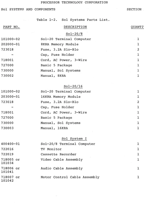
Sol Systems Parts List. . Sol Power Supply Parts List .
Sol~PC Parts List . • .
PM2708/92l6 Personality Module Parts List Sol-20 Cabinet-Chassis Parts List • • . • • Sol Operating Controls and Their Functions. Baud Rate Selection with Switch S3 . .
Word Length Selection with S4-2 & 3 • Sol Keyboard Assignments.
Control Character Symbols and Definitions .
· VIII-30 · VIII-31
PAGE
1-5-13 1-14,15 11-2-4 111-2-7
IV-2 VI-2,3 VII-2 VII-15 VII-15 VII-18-2l VII-23 8-1 Port Decoder (U35 & 36) Outputs and
Their Functions . . . • • . . . VIII-17
1.2 General Information . . • . 1.2.1
1.2.2 1. 2.3
Sol-20 Description . Service. . . • Replacement Parts. 1.3 Receiving Inspection . • •
1.4 1.5
1.3.1 1.3.2
Sol Kits • • . . • • • • • Assembled Sol Kits . . Section X Drawings . . • . Sol Kit Assembly Order • •
1.1 INTRODUCTION
This manual consists of nine separate sections presented in the preferred order of usage for the kit builder, a section of assem-bly drawings and schematics, appendices of useful information, and a section of updates.
Integrate the update information into this manual before doing anything else. Then finish reading this section completely, follow-ing the suggestions provided and performfollow-ing the specified inspections.
Sections II, III, IV, V and X primarily supply assembly in-structions and aids for the kit builder. The owner of a factory assembled unit, however, will find some of the test procedures and chassis-cabinet assembly instructions and drawings useful when ser-vicing Sol. Operating Procedures (Section VII), Theory of Operation
(Section VIII) and Software (Section IX) will be of interest to both the kit builder and assembled unit owner.
Three special features are incorporated in this manual to make i t easier and more efficient to use. They are 1) an "easel" binder to facilitate reading while you work with your Sol, 2) an instruction and component installation check-off format to minimize omitting pro-cedural steps, and 3) foldout drawings printed on one side only. The third feature eliminates much page juggling since a drawing, when
folded out, is not obscured by the text pages. 1.1.1 To the Sol Kit Builder
For the Sol kit builder, this manual supplies the information needed to assemble, test and operate the Sol-PC Single Board Computer and the Sol-20 Terminal Computer Systems. As anxious as you are to assemble your kit, we suggest that you first take the time to read this section and scan the rest of the manual before making any in-spections or starting assembly. (The time you take to "get on board Sol," so to speak, will be time well invested.) Then proceed with the receiving inspection and assembly. When assembling your kit, follow the instructions in the order given.
Should you run into a problem during assembly, calIon us, or your Sol dealer, for help if necessary. If your completed kit does not work properly, recheck your assembly step by step. Most problems stern from poor soldering, failure to follow the instructions, back-ward installed components and/or installing the wrong component. OnCE your are satisfied that your Sol is correctly assembled, feel free to ask us, or your Sol dealer, for assistance if you still have trouble. 1.1.2 To Factory Assembled Sol Owners
For those who purchased a factory assembled and tested unit, this manual supplies the information needed to start you on the way
stand how Sol works and how to service it. As anxious as you are to use Sol, we suggest that you first take the time to read this section and scan Sections ·VI!, VIII, IX and Appendices AVI and AVIII. (The time you take to "get on board with Sol," so to speak, will be time well invested.) Theh proceed with the receiving inspection, and~ using Section VII as your guide, connect the basic Sol system, place i t into operation and get acquainted with Sol by putting i t through some sim-ple operations. When doing this, follow the instructions in the order given.
Since your unit was factory assembled and tested before ship-ment, your Sol should operate correctly. If i t doesn't, recheck your interconnect cabling. If a problem persists, feel free to ask us, or your Sol dealer, for assistance.
1.2 GENERAL INFORMATION 1.2.1 Sol-20 Description
Except for the power supply and keyboard, the Sol-20 Terminal Computer electronics is contained on the Sol-PC. The Sol-20 is built around an 8080 microprocessor. Integral support circuitry permits full implementation of every 8080 function. Use of the popular S-lOOI. bus assures compatibility with a large variety of memory boards and peripheral devices.
Sol-20 features an 85-key integral keyboard, both parallel and serial communications interfaces, an audio cassette tape inter-face, a video display generator, 1024 8-bit words of system RAM
(random access memory), 1024 8-bit words of display RAM, and a plug-in personality module with up to 2048 bytes of stored program on ROM
(read only memory) .
Parallel interfacing is eight bits each for input and output plus control handshaking signals, and the output bus is tri-stated TTL for bidirectional interfaces. The serial interface includes both asynchronous RS-232 and 20 rnA current loop provisions with transmission rates of 75 to 9600 Baud (switch selectable).
The dual rate, 300 or 1200 bps (bits per second), audio cas-sette interface is program-controlled and self-clocking with a phase-lock loop. It includes automatic level control. Recording is CUTS/ Byte Standard compatible, asynchronously Manchester coded at 1200/ 2400 Hz or 600/1200 Hz.
with switch selectable blink, may be programmed. The display output is standard EIA, 1.0 to 2.5 V peak-to-peak with composite negative sync, and a nominal 7 MHz bandwidth. It can thus be used to drive any standard video monitor. (A monochrome TV, converted for video input, can also be used. See Appendix VI.)
Included in the Sol are 1024 words of static, low power sys-tem RAM capable of full speed operation and a plug-in personality module that contains the software monitor, or control,program. Three personality modules are available for Sol:
SOLOS--allows full stand-alone terminal/computer operation. It permits data storage and retrieval, control of electronic instruments and independent calculations. In general, SOLOS is the choice when the Sol system will be lion its own" operating independently of other computers. SOLOS is the standard personality module supplied with the Sol-20.
PM2708--permits customized software with 2708 EPROMS (not supplied) for special applications.
BOOTLOAD--same as SOLOS except that the SOLOS ITERMinal" com-mand is replaced with a bootstrap loader program for use with the Helios II disk memory system.
Your Sol Computer power is easily expanded since i t is compat-ible with all S-IOO bus products. Sol-20 has a capacity for five ex-pansion modules. Add-on memory and interface modules are available from Processor Technology as well as a host of software cassettes. Processor Technology also has a number of quality peripheral devices to work with Sol, including a TV monitor and cassette recorder.
1. 2.2 Service
Service of all kinds is the responsibility of the dealer from whom you purchased your Sol-PC or Sol System. Contact the dealer if you have problems completing assembly and testing, or your Sol mal-functions and you cannot correct the problem.
1. 2.3 Replacement Parts
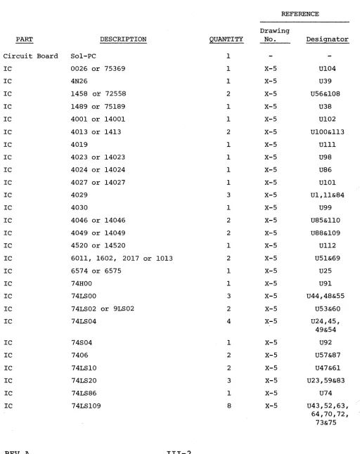
Order replacement parts from Processor Technology or your Sol dealer. When ordering, specify our part number, component descriptiol
(74LSI09 IC (integrated circuit), 2N2222 transistor, and 680 ohm, 1/4 watt, 5% resistor for example). Processor Technology part numbers
for Sol components and assemblies are given in Tables 1-1 and 1-2.
1. 3.1 Sol Kits
Examine the shipping container(s) for signs of possible damage to the contents during transit. Then inspect the contents for damage.
(We suggest you save the shipping materials for use in returning the kit to Processor Technology should i t become necessary to do so.) If your Sol kit is damaged, immediately contact the carrier, and please write us at once describing the condition so that we can take appro-priate action.
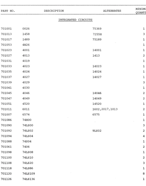
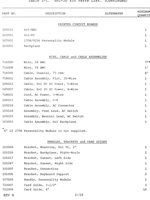
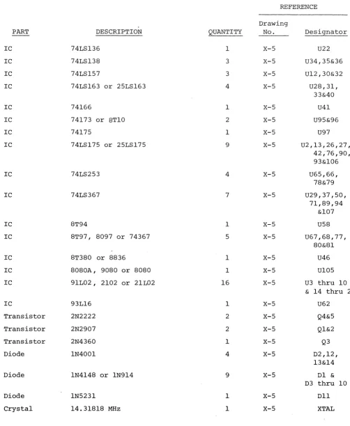
Then check all of the parts and components against Table 1-1 (Table 3-1 if you have a Sol-PC kit). Table 1-1 is a consolidated listing of the parts lists in Sections II, III, IV and VI. It lists the Processor Technology part number, description, alternate (if any), and minimum quantity for each part in the complete Sol-20 Terminal Computer kit. Note that some parts have alternates. An alternate is equivalent to its primary part and may be used in any location for which the primary part is specified. Where indicated in Table 1-1, alternates may be supplied with your kit in lieu of primary parts, and in some cases you may receive, for a given primary part, a combination of the primary and/or alternates. For examole,you co~ld receive one
8T97, two 8097 and two 74367 for the five 8T97's specified in Table 1-1; any of these may be used in any place that calls for an 8T97.
(Also use Table 1-1 to find our part number for any replacement part you order.)
Figure 3-1 in Section III, Figures 6-1 and 6-2 in Section VI and Drawings X-I through X-IO will help you identify unfamiliar parts. Should a part be missing, please contact us at once so that we can take appropriate action.
1. 3.2 Assembled Sol Units
Examine the shipping container(s) for signs of possible damage to the contents during transit. Then inspect the contents for damage. (We suggest that you save the shipping materials for use in returning you Sol unit to Processor Technology should i t become necessary to do so.) If your Sol unit is damaged, immediately contact the carrier, and write us at once describing the condition so that we can take ap-propriate action.
Then check the contents against Table 1-2 to be sure you re-ceived everything. Table 1-2 identifies all Sol System assemblies and parts.and lists their quantity and Processor Technology part num-ber. Should anything be missing, please contact us at once so that we can take appropriate action. If you need to order a replacement
part or assembly sometime in the future, use the parts lists in SectiC'--II, ISectiC'--II, IV and VI, in conjunction with Tables 1-1 and 1-2, to deter-mine our part number and description.
PART NO.
701001 0026
701013 1458
701017 1489
701053 4N26
701023 4001
701027 4013
701031 4019
701033 4023
701035 4024
701037 4027
701039 4029
701041 4030
701045 4046
701047 4049
701051 4520
701011 6011
701007 6574
701086 74HOO
701090 74LSOO
701092 74LS02
701094 74LS04
701088 74S04
701061 7406
701098 74LS08
701100 74LS10
701108 74LS20
701118 74LS86
701120 74LS109
701126 74LS136
REV A
Table 1-1. Sol-20 Kit Parts List.
DESCRIPTION
INTEGRATED CIRCUITS
[image:11.612.74.562.126.750.2]PART NO. 701128 701138 701142 701075 701077 701079 701146 701150 701158 701164 701166 701184 701186 701178 701170 701019 726004 701192
*
DESCRIPTION 74LS138 74LS157 74LS163 74166 74173 74175 74LS175 74LS253 74LS367 7812 7912 8T94 8T97 8T380 8080A 91L029216* (marked "SOLOS")
93L16
ALTERNATES
25LS163
8TIO
25LS175
8097, 74367
8836
9080, 8080
2102, 21L02
9216 Personality Module only.
702016 702002 702004 702010 703001 703003 703005 TIP41 2N2222 2N2907 2N4360 IN270 IN4001 IN4148 TRANSISTORS
DIODES and BRIDGE RECTIFIERS
Table 1-1. Sol-20 Kit Parts List. (Continued)
PART NO. DESCRIPTION ALTERNATES
703011 1N5231
703029 101
703027 106-2 10632
703031 970-1
703033 980-1
*
4 if 2708 Personality Module is supplied.RESISTORS
705002 0.1 ohm, wire wound, 5W
705005 6.8 ohm, 1/2 W, 5%
705009 39 ohm, 2 W, 5%
705011 47 ohm, 1/4 W, 5%
705013 68 ohm, 1/4 W, 5%
705015 75 ohm, 1/4 W, 5%
705017 100 ohm, 1/4 W, 5%
705019 100 ohm, 1/2 W, 5%
705018 130 ohm, 1/2 W, 5%
705023 200 ohm, 1/4 W, 5%
705026 270 ohm, 1/4 W, 5%
705025 330 ohm, 1/4 W, 5%
705027 330 ohm, 1/2 W, 5%
705031 470 ohm, 1/4 W, 5%
705033 470 ohm, 1/2 W, 5%
705035 680 ohm, 1/4 W, 5%
705041 1K ohm, 1/4 W, 5%
705043 1. 5K ohm, 1/4 W, 5%
705045 1.69K ohm, 1/4 W, 1%
705052 3.3K ohm, 1/4 W, 5%
705053 4.02K ohm, 1/4 W, 1%
*
2708 Personality Module Only.REV A 1-7
MINIMUM QUANTITY
2*
1
1 1
1
1
2
1
3
1
1
2
3
2*
1
1
15
1
1
2
9
2
63
1
1
PART NO. DESCRIPTION ALTERNATES
705055 4.7K ohm, 1/4 W, 5%
705057 5.6K ohm, 1/4 W, 5%
705061 10K ohm, 1/4 W, 5%
705065 15K ohm, 1/4 W, 5%
705071 39K ohm, 1/4 W, 5%
705072 47K ohm, 1/4 W, 5%
705073 50K ohm, variable
705075 56K ohm, 1/4 W, 5%
705081 lOOK ohm, 1/4 W, 5%
705074 lOOK ohm, variable
705083 150K ohm, 1/4 W, 5%
705085 1M ohm, 1/4 W, 5%
705089 2.2M ohm, 1/4 W, 5%
705091 3.3M ohm, 1/4 W, 5%
**
39 i f 2708 Personality Module is supplied.
CAPACITORS
707001 10 pf, Disc Ceramic
707005 330 pf, Disc Ceramic
707009 470 pf, Disc Ceramic
707011 680 pf, Disc Ceramic
707015 .001 llf, Disc Ceramic
707017 .001 llf, Mylar
707021 .01 llf, Mylar
707023 .047 llf, Disc Ceramic
707025 .1 llf, Disc Ceramic
707027 .1 llf, Mylar
707029 .68 llf, Mono Ceramic
707032 1 llf, Tantalum
707036 15 llf, Tantalum
*5 if 2708 Personality Module is supplied.
MINIMUM QUANTITY
1
6
38**
2
2
2
2
1
3
1
2
2
1
2
1
1
1
3
6
2
2
39 14
1
1
2*
PART NO. 707038 707041 707047 707049 713002 713004 713006 713012 713014 717002 717019 717011 717013 717044 717045 717042 717043 717047 719001 719002 719003 724005
*
Table 1-1. Sol-20 Kit Parts List. (Continued)
DESCRIPTION J\.LTERNATES
100 ]If, Aluminum 2500 ]If, Aluminum
18,000 ]If, Aluminum
54,000 ]If, Aluminum
SOCKETS, CONNECTORS and HEADERS DIP, 8-pin
DIP, l4-pin DIP, l6-pin DIP, 24-pin DIP, 40-pin
Header, Male, 20-pin Header, Male, 7-pin Socket, Female, 25-pin Socket, Male, 25-pin
Socket, Phone Jack, Miniature Socket, Phone Jack, Subminiature Socket, Coax, 75 ohm
Plug, Coax 75 ohm Sleeve, Adapter, Coax
Connector, PC, 100-pin Connector, PC, 100-pin Connector, PC, 30-pin
Commoning Block, 5 position
3 if 2708 Personality Module is supplied.
SWITCHES, RELAYS and HOLDERS
723002 Switch, DIP, 6 Section
723003 Switch, DIP, 8 Section
723005 Switch, AC Power
723010 Relay, DIP, 500 ohm Reed
724007 Holder, Fuse
REV A I-9
PART NO. 105010 102002 107001 103001 716000 716008 716005 718002 105012 105007 718001 105013 105018 105024 105025 103003
*
DESCRIPTION ALTERNATES
PRINTED CIRCUIT BOARDS
Sol-REG
Sol-PC
2708/9216 Personality Module
Backplane
WIRE, CABLE and CABLE ASSEMBLIES
Wire, 24 AWG
Wire, 24 AWG
Cable, Coaxial, 75 ohm
Cable Assembly, Flat, 20-Wire
Cable, Sol PC DC Power, 5-Wire
Cable, Sol 20 DC Power, 4-Wire
Cord, AC Power, 3-Wire
Cable Assembly, C-8
Cable Assembly, AC Connector
Assembly, Fuse Lead, AC Switch
Assembly, Neutral Lead, AC Switch
Cable Assembly, Sol Backplane
6" if 2708 Personality Module is not supplied.
102004 101016 101017 101047 101005 101006 107009 722007 722009
HANDLES, BRACKETS and CARD GUIDES
Bracket, Mounting, Sol PC, 2"
Bracket, Backplane, Right-Angle
Bracket, Gusset, Left Side
Bracket, Gusset, Right Side
Bracket, Connecting
Bracket, Keyboard Support
Handle, Personality Module
Card Guide, 2-1/2"
Card Guide, 4"
[image:16.612.70.569.106.771.2]PART NO. 101003 105019 101004 101002 101020 101015 105020 101007 101008 101012 101014* 101032 101019 *
May be
720074 720075 720002 720001 720003 720013 720014 720049 720038 720025 720040 717051 720010
REV A
Table 1-1. Sol-20 Kit Parts List. (Continued)
DESCRIPTION
CHASSIS, COVERS and LABELS
Chassis, Main
Subchassis, Power Supply
Subchassis, Expansion
Cover, Keyboard
Cover, Top
Cover, Logo, P1exig1ass
Plate, Fan Closure
Assembly, Side Panel, Left
Assembly, Side Panel, Right
Label, Serial Number
Label, Sol Logo*
Label, Connector
Label, Fingerwe11, Black
packaged under logo cover.
HARDWARE
Machine Screw, 2-56 x 3/16
Lockwasher, Internal Tooth, #2
Machine Screw, 4-40 x 1/4
Machine Screw, 4-40 x 3/16
Machine Screw, 4-40 x 5/16
Machine Screw, 4-40 x 7/16
Machine Screw, 4-40 x 5/8
Spacer, 4-40 x 1/4
Lockwasher, Internal Tooth, #4
Lockwasher, Spring, #4
Flat Washer, Nylon, #4
Lug, #4
Hex Nut, 4-40
I-II
[image:17.612.73.559.184.752.2]PART NO. 720020 720019 720022 720023 720026 720041 720067 720011 720032 720051 720012 720036 720079 717053 720042 709004 105033 722003 105028 105034* 104000 723018 105011 721004 721006 721000 713018 720060 DESCRIPTION
Machine Screw, Metal, 6-32 x 1/2
Machine Screw, Nylon, 6-32 x 1/2 Machine Screw, 6-32 x 3/4
Sheetmetal Screw, #6 x 1/4 Self-tapping Screw, #6 x 5/16
Lockwasher, Internal Tooth, #6 Flat Washer, #6
Hex Nut, 6-32
Machine Screw, 8-32 x 1/2 Lockwasher, Internal Tooth, #8
Hex Nut, 8-32
Machine Screw, 10-24 x 3/8 Machine Screw, 10-24 x 1
Lug, #10
Screw, Quick Connect, Knurled
MISCELLANEOUS Crystal, 14.31818 MHz
Fan Assembly Finger Guard, Fan
Transformer, Sol 20 Transformer, 220/240 V* Keyboard Assembly, 85 Key Fuse, 3.2A, Slo-Bl0
Heatsink Heatsink Heatsink
Heatsink Compound Augat Pins
Clamp, 1-1/2
ALTERNATES
*Sol 20/220 and Sol 20/240 only.
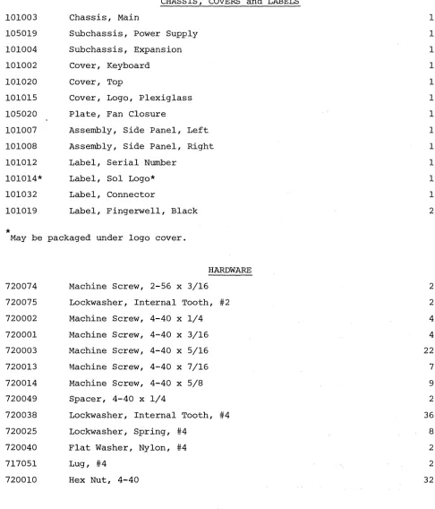
Table 1-1. Sol-20 Kit Parts List. (Continued)
PART NO. DESCRIPTION ALTERNATES MINIMUM
QUANTITY
720061 Clamp, 2-1/2" 1
720046 Washer, Mica, TO-220 2
720062 Washer, Mica 1
722011 Tie, Cable 5
716004 Tubing, PVC 3"
722017 Foot, Rubber, Adhesive 4
716001 Solder, 60/40, 20SWG 31'
727000 Basic 5 Package 1
730000 Manual, Sol Systems 1
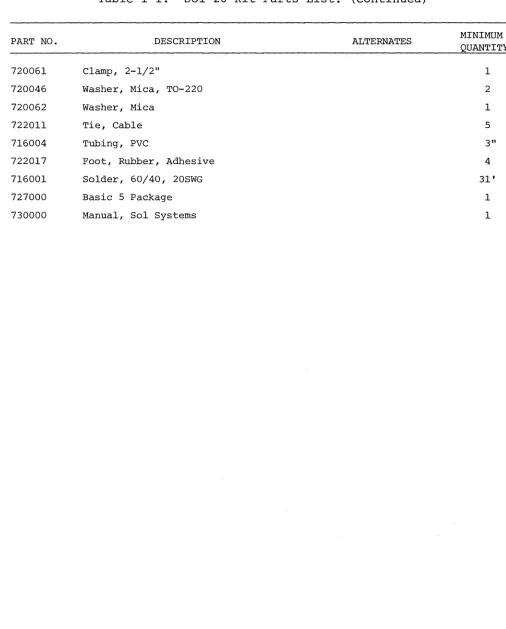
[image:19.612.67.573.109.738.2]PART NO. 101000-02 202000-01 723018 718001 727000 730000 730002 101000-02 203000-01 723018 718001 727000 730000 730003 400400-01 722016 722019 718005 or 101034 718006 or 101041 718007 or 101042
REV A
. DESCRIPTION Sol-20/8 Sol-20 Terminal Computer 8KRA Memory Module
Fuse, 3.2A Slo-Bl0 Cap, Fuse Holder
Cord, AC Power, 3-Wire Basic 5 Package
Manual, Sol Systems Manual, 8KRA
Sol-20/16 Sol-20 Terminal Computer 16KRA Memory Module
Fuse, 3.2A Slo-Bl0 Cap, Fuse Holder
Cord, AC Power, 3-Wire Basic 5 Package
Manual, Sol Systems Manual, 16KRA
Sol System I Sol-20/8 Terminal Computer TV Monitor
Cassette Recorder Video Cable Assembly Audio Cable Assembly
Motor Control Cable Assembly
[image:20.612.67.561.31.744.2]PART NO.
400500-01 722016 722019 718005 or 101034 718006 or 101041 718007 or 101042
400500-01 203100 300000-01 722016 718005 or 101034 727036 730009
REV A
Table 1-2. Sol Systems Parts List. (Continued)
DESCRIPTION Sol System II
Sol-20/16 Terminal Computer TV Monitor
Cassette Recorder Video Cable Assembly Audio Cable Assembly
Motor Control Cable Assembly
Sol System III Sol-20/16 Terminal Computer
32KRA Memory Module (or two 16KRA Memory Modules, PIN 203000-01) Helios II
TV Monitor
Video Cable Assembly
Extended Disk Basic Package Manual, Helios II
1-15
QUANTITY
1
1
1
1
1
1
1
1
1
1
1
1
the following procedure to internally inspect the unit, and if re-quired, install the memory module:
CAUTION
DO NOT TOUCH ANY OF THE Sol-PC COMPONENTS, OR Sol-20 INTERNAL COMPONENTS, UNTIL IN-STRUCTED TO DO SO IN THE FOLLOWING PRO-CEDURE.
1. On the Sol-20, remove the two knurled quick connect screws (located on back of Sol) that hold the top cover in place. 2. On the Sol-20, refer to Drawing X-10 in Section X and
carefully swing the top cover up, unhook i t from the back edge of the keyboard cover, and set i t to one side.
3. On the Sol-20, carefully swing keyboard cover up, unhook i t from the front edge of the main chassis, and set i t to one side.
4. On the Sol-20, touch the chassis to discharge any static electricity. (On the Sol-PC this may be accomplished by touching the ground trace along the edge of the board.) Visually inspect all IC's, the personality module and
cable connectors to see if they are firmly seated. Secure any" loose cable connectors and push gently down on any loose IC's until they are fully seated in their socket. If the personality module is loose, push on its handle
(see Drawing X-7 in Section X) to seat the module firmly in its socket.
5. On the Sol-20, install the memory module(s} in the expan-sion chassis (located in left rear corner of Sol as viewed from the front). You may install the module(s} in any of the five card slots. With the component side up, insert edge connector side of module in card guides and carefully slide the module in until the edge connector is fully
seated in the backplane (the vertical circuit board on the front side of the expansion chassis) connector.
6. For the Sol-20, reassemble i t by hooking the keyboard cover under the front edge of the main chassis and lower-ing i t over the keyboard, hooklower-ing the top cover over the back edge of the keyboard cover and lowering i t down into place over the rear of the unit, and installing the two knurled quick connect screws.
B. With AC power cord hot plugged into a 110 V ac outlet, connect power cord to AC connector on Sol rear panel (see Figure 7-1).
If you have a Sol-PC, i t is now ready to use with a keyboard and TV monitor. If you have a Sol-20, you are now ready to simultan-eously test the Sol functions and get acquainted with its operation. Information in Section VII ("Sol Operating Procedures") and IX
("Software") will guide you.
Should you have any problem getting Sol to respond as described in Sections VII and IX, make sure that you faithfully followed all of the instructions. If that does not remedy the situation, feel free to seek help from us or your Sol dealer.
1.4 SECTION X DRAWINGS
This overview of the drawings section in this manual (Section X) is intended to help you better utilize the drawings supplied there-in.
The first 10 drawings (X-l through X-lO) are assembly drawings which the kit builder will use to assemble his kit. They also pro-vide information that will be useful when servicing the Sol-PC or Sol-20. Drawing X-II is a functional block diagram of the Sol-PC, the primary "horne" for the Sol electronics. This diagram includes a
table that relates the functional blocks with the applicable schema-tic(s) and the IC's used. Drawings X-12 and 13 are schematics of the Sol Regulator and Power Supply, respectively.
The Sol-PC schematic is separated by functional sections into five separate schematic drawings (X-14 through X-lB). Notes that ap-ply to all five schematics are provided on Drawing X-lB. To assist you in relating the schematics to the block diagram, each schematic incorporates grey, identified blocks for each functional block on Drawing X-II.
Drawing X-19 is the schematic for the 270B/92l6 Personality Module, and the remaining drawings (X-20 through X-23) pertain to
the Keyboard Assembly.
1.S Sol KIT ASSEMBLY ORDER
If you are building a Sol-PC, either start assembly with Section III (Sol-PC) or IV (Personality Module). The assembly of these two parts is inter-related, so you may begin with either one.
The recommended assembly order for the Sol-20 is to first build the power supply. You then have the option of starting to
build the Personality Module (Section IV) or the Sol-PC (Section III) since the assembly of these two parts is inter-related. Having
2.2 2.3
Parts and Components . . Assembly Tips • • .
2.3.1 2.3.2
Electrical . • Mechanical. 2.4 Assembly Precautions
II-l II-5 II-5 II-5 II-6 2.5 Required Tools, Equipment and Materials. . II-6 2.6 Orientation
2.7
2.6.1 Sol-REG PC Board . . 2.6.2 Fan Closure Plate. Assembly-Test. • .
2.7.1 2.7.2 2.7.3
Fan Closure Plate Assembly • . . • . Sol-REG Assembly and Test . . . . • • . Power Supply Subchassis
Assembly and Test . • . • • .
The Sol power supply consists of a regulator board plus addi-tional chassis-mounted components. This section covers assembly and test of the complete power supply.
2.2 PARTS AND COMPONENTS
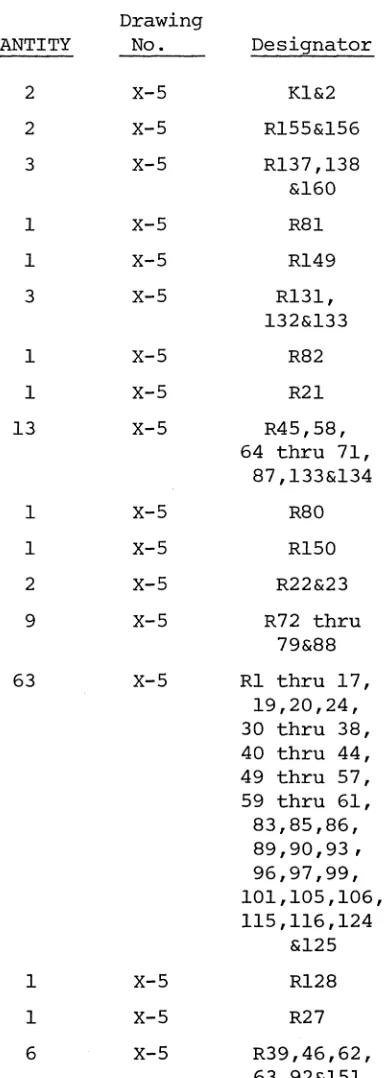
You will need the parts listed in Table 2-1 to assemble your Sol power supply. Select and separate the needed parts from those supplied with your Sol kit before starting assembly. If you have any difficulty in identifying any parts by sight, refer to Figure 3-1 in Section III, Figure 6-1 in Section VI and the "Standard Color Code for Resistors and Capacitors" chart in Appendix III. The assembly draw-ings in Section X will also be useful in identifying parts.
To guide you in selecting and identifying parts, Table 2-1 lists each part, its description, quantity ~nd reference designation on the drawing(s) you will use in assembling the power supply. You will encounter two types of reference designators in Table 2-1 (and parts lists in Section III, IV and VI as well): alphanumeric and en-circled numeric designators.
Alphanumeric designators (Cl, R5, U3, D4, etc.) are used to identify electronic components such as capacitors, resistors, inte-grated circuits and diodes. Encircled desigHators
(CD,
®, ®,
etc. are used to identify the other parts used in the Sol (chassis, cables, screws, washers, covers, heat sinks, etc.). Two examples of how to use the information in Table 2-1 follow:1. Alphanumeric Designators. The first integrated circuit (IC) entry in Table 2-1 indicates its reference designa-tor is U2 and that U2 will be installed using Drawing X-2 in Section X. In looking at Drawing X-2, we can see that U2 (a 1458) is an 8-pin dual inline package (DIP) IC that will be installed in the near center of the Sol-REG board. 2. Encircled Numeric Designators. The next to last entry in
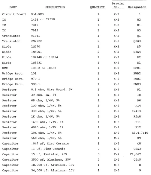
Table 2-1. Sol Power Supply Parts List.
REFERENCE
Drawing
PART DESCRIPTION QUANTITY No. Designator
Circuit Board Sol-REG 1 X-2 1
IC 1458 or 72558 1 X-2 U2
IC 7812 1 X-2 Ul
IC 7912 1 X-2 U3
Transistor TIP41 1 X-2 Ql
Transistor 2N2222 2 X-2 Q2&3
Diode IN270 1 X-2 D5
Diode IN4001 2 X-2 D3&4
Diode IN4148 or IN914 1 X-2 D2
Diode IN5231 1 X-2 Dl
SCR 106-2 or 10632 1 X-2 SCRI
Bridge Rect. 101 1 X-2 FWB2
Bridge Rect. 970-1 1 X-2 FWBI
Bridge Rect. 980-1 1 X-3 FWB3
Resistor 0.1 ohm, Wire Wound, 5W 1 X-2 Rl
Resistor 39 ohm, 2W, 5% 1 X-3 10
Resistor 68 ohm, 1/4W, 5% 1 X-2 R6
Resistor 100 ohm, 1/4W, 5% 1 X-2 R14
Resistor 330 ohm, 1/4W, 5% 2 X-2 R2&13
Resistor lK ohm, 1/4W, 5% 2 X-2 R5&8
Resistor 1690 ohm, 1/4W, 1% 1 X-2 Rl1
Resistor 4020 ohm, 1/4W, 1% 1 X-2 R12
Resistor 10K ohm, 1/4W, 5% 4 X-2 R3,4,7&10
Resistor 56K ohm, 1/4W, 5% 1 X-2 R9
Capacitor .047 ].If, Disc Ceramic 1 X-2 C8
Capacitor .1 ].If, Disc Ceramic 2 X-2 C2&3
Capacitor 15 ].If, Tantalum, 20V 3 X-2 C1,6&7
Capacitor 2500 ].If, Aluminum, 25V 2 X-2 C4&5
Capacitor 18,000 ].If, Aluminum, 10V 1 X-3 8
Capacitor 54,000 ].If, Aluminum, 15V 1 X-3 9
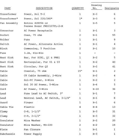
[image:27.612.67.570.152.737.2]PART
Transformer Transformer*
Fan Assembly
Connector Socket Holder Switch Block Fuse
Heat Sink Heat Sink Heat Sink Cable Cable Cable Cable Cord Lead Lead Guard Cable Tie Clamp Clamp Insulator Insulator Plate Subchassis
*
DESCRIPTIONPower, Sol T-2 Power, Sol 220/240*
Rotron 428056 or
Peewee Boxer PWS2l07FL-2-M AC Power Receptacle
Coax, 75 ohm Fuse
AC Power, Alternate Action Commoning, 5 position
3.2A, Slo-Blo
Bar, For SCRl, Ql & FWBI Rectangular, For Ul & U3 Circular, For Q2
Coaxial, 75 ohm
C8 Cable Assembly, 2-Wire Sol-PC Power, 4-Wire Sol 20 DC Power, 5-Wire AC Power, 3-Wire
Fuse Lead to AC Switch, 3" Neutral Lead, AC Switch, 3-1/4" Finger
Plastic C-8, 1-1/2" C-9, 2-1/2" Mica Washer
Mica Washer, TO-220 Fan Closure
Power Supply
QUANTITY 1 1* 1 1 2 1 1 2 1 1 1 1 15" 1 1 1 1 1 1 1 4 1 1 1 2 1 1
Supplied only with 220 and 240 Vac versions of Sol.
REFERENCE
Drawing
No. Designator
X-3 6
X-3 6
X-5 5
[image:28.612.74.551.154.707.2]Table 2-1. Sol Power Supply Parts List (Continued)
REFERENCE
Drawing
PART DESCRIPTION QUANTITY No. Designator
Screw Machine, 4-40 x 3/16 2 X-3 20
X-I 14
Screw Machine, 4-40 x 5/16 6 X-3 18
Screw Machine, 4-40 x 7/16 1 X-2 44
Screw Machine, 4-40 x 5/8 1 X-2 45
Spacer Tapped, 4-40 x 1/4 2 X-3 30
X-I 18
Lockwasher Internal Tooth, #4 9 X-2 48
X-3 29
X-I 16
Hex Nut 4-40 6 X-2 50
Lug #4 2 X-1 58
X-I 13
Screw Machine, Metal, 6-32 x 1/2 16 X-2 47
X-3 16
Screw Machine, Nylon, 6-32 x 1/2 2 X-2 46
Screw Machine, Metal, 6-32 x 3/4 1 X-3 19
Screw Self-tapping, #6 x 5/16 4 X-3 17
X-I 17
Lockwasher Internal Tooth, #6 22 X-2 52
X-3 28
X-I 15
Hex Nut 6-32 22 X-2 51
X-3 24
Screw Machine, Metal, 8-32 x 1/2 3 X-3 15
Lockwasher Internal Tooth, #8 3 X-3 27
Hex Nut 8-32 3 X-3 23
Lug #10 2 X-3 12
Compound Heats ink 1
Solder 60/40, 20 SWG
2.3.1 Electrical
For the most part the assembly tips given in Paragraph 3.2 of Section III (Page III-I) apply to assembling the Sol regulator board and power supply.
In addition, scan Section II completely before you start to assemble the power supply.
2.3.2 Mechanical
1. If you do not have the proper screwdrivers (see Para-graph 2.5), we recommend that you buy them rather than using a knife point, a blade screwdriver on a Phillips screw, and other makeshift means. Proper screwdrivers minimize the chances of stripping
threads, disfiguring screw heads and marring decorative surfaces. 2. To assure a correct fit and tight assembly, be sure you use the screws specified in the instructions.
3. Lockwashers are widely used in the power supply assembly so that screws will not loosen when subjected to stress or vibration. Wnen a lockwasher is specified, do not omit i t and make sure you
install i t correctly. .
4. Some instructions call for prethreading holes. This is done to make assembly easier by giving you maximum working space for installing relatively hard-to-drive sheet metal screws. If you by-pass prethreading instructions you will only make subsequent
cabinet-chassis assembly more difficult.
To prethread a hole, insert specified screw in the hole and position i t as straight as possible. While holding the screw in this position, drive i t into the metal with the proper screwdriver. If started straight the screw will continue to go straight into the metal so that the head and sheet metal surfaces are in full contact.
5. The diameter of the shank increases in relation to its number. larger in diameter than a 4-40 screw. larger than a #4 lockwasher.
(threaded portion) of a screw For example, a 6-32 screw is
Also, a #8 lockwasher is
6. Heat sink compound is supplied with this kit in a small clear plastic package. I t is a thick white substance which improves heat transfer between components and their heat sinks. To use
the compound, pierce a small hole near the edge of the top surface of the plastic package, using a pin or sharp knife point. Squeezing the package will cause a small amount of the compound to ooze out
-out of the hole, which may then be applied with a toothpick or small screwdriver blade. Spread a thin film of the compound on the mating surfaces of both the heat-generating component and the heat sink sur-face which i t will contact. Then assemble as directed.
2.4 ASSEMBLY PRECAUTIONS
The precautions concerning soldering and the installation and removal of integrated circuits given in Paragraph 3.3 of Section III
(Page 111-9) also apply to assembling the Sol regulator board.
2.5 REQUIRED TOOLS, EQUIPMENT AND MATERIALS
The following tools, equipment and materials are recommended for assembling the Sol regulator board:
1. Needle nose pliers 2. Diagonal cutters 3. Sharp knife
4. Screwdriver, thin 1/4" blade 5. Screwdriver, #2 Phillips
6. Controlled heat soldering iron, 25 watt 7. volt-ohm meter
8. Ruler
2.6 ORIENTATION
2.6.1 Sol-REG PC Board
Location C5 (2500 ufd capacitor) will be located in the lower right-hand corner of the circuit board when locations SCRl, Ql and FWBI are positioned along the top of the board. In this position the component (front) side of the board is facing up and the horizontal legends will read from left to right; the other legends will read from bottom to top. Subsequent position references related to the Sol~REG
board assume this orientation. 2.6.2 Fan Closure Plate
The large circular cutout will be located in the upper right quadrant of the plate when the heavy gauge doubler plate is facing up. In this position the rectangular cutouts are on the left, the front side of the plate is facing down, the back side is facing up, and the-small circular cutout is at the bottom:- We suggest you label the two sides.
2.7.1 Fan Closure·Plate Assembly
Refer to Assembly Drawings on Pages X-l and 4 in Section X. (Figure 2-1 shows a completed fan closure plate assembly.)
Figure 2-1. Sol-20 fan closure plate assembly. (Top of plate in foreground.)
( ) Step 1. Mount cooling fan and guard to fan closure plate. Insert four 6-32 x 1/2" binder or pan head screws from back side (side with doubler plate) of fan closure plate. (Use the holes positioned in each quadrant of the large circular cut-out.) Slip fan guard over screws on front side of plate (side without doubler plate side). Position fan with motor support struts away from front side of closure plate and with its leads next to the rectangular cutouts in the plate. Place #6 lockwasher on each screw and secure with 6-32 hex nut.
WARNING
FAILURE TO INSTALL FAN GUARD MAY RESULT IN DAMAGE TO THE Sol AND/OR PERSONAL INJURY.
( ) Step 2. Install power on-off switch in upper rectangular cut-out in fan closure plate.
Bend four retainer tabs on switch in and position switch with terminals facing front side of fan closure plate. Push switch unit from back side of plate through mounting hole and bend retainer tabs outward if needed to hold switch in place.
( ) Step 3. Install commoning blocks (Item 10 on drawing on Page X-I) on front side of fan closure plate, one on each side of on-off switch.
position each block with terminal #1 at top and terminal #5 at bottom and attach each block to front side of fan closure plate with two 6-32 x 1/2 binder or pan head screws. Insert screws from back side of plate, place block over screws, on front side of plate, put #6 lockwasher on each screw and se-cure with 6-32 hex nut.
( ) Step 4. Install fuse holder in mounting hole located between the two rectangular cutouts in the fan closure plate.
Insert fuse holder from back side of plate, position large tab at top, next to on-off switch, and secure holder to plate with the large lockwasher and nut supplied with holder.
( ) Step 5. Install AC Power cord receptacle on fan closure plate. position receptacle on front side of fan closure plate over the rectangular cutout below fuse holder. Orient receptacle with green lead at the bottom and align the receptacle and closure plate mounting holes. Insert two 6-32 x 1/2 binder or pan head screws from back side of plate through each mount-ing hole, put #6 lockwasher on each screw and secure with 6-32 hex nut. Be sure receptacle is properly seated in cut-out before tightening to avoid damage.
( ) Step 6. Install female coaxial connector on fan closure plate. Insert connector from front side of plate so that the threaded end projects through to the back side. Then insert four
4-40 x 5/16 binder or pan head screws from back side of plate through the four connector and plate mounting holes. Place #4 lockwasher on each screw except the upper one which is closest to the AC receptacle. Secure with 4-40 hex nuts.
(Leave upper nu~closest to receptacle loose.)
( ) Step 7. Prepare RG59/U coaxial cable. (See Figure 2-2.)
REV C
Cut a 15" piece of coaxial cable from that supplied. Strip away 1-1/2 inch of the outer insulation at both ends to ex-pose shield. Unbraid shield at one end and loosely twist i t into a single lead. Do the same thing at the other end. Tin shield lead at each end and solder a #4 lug to each lead.
Then remove one inch of the inner conductor insulation at both ends and cut inner conductor to 3/8" length.
Figure 2-2. Coaxial cable preparation.
( ) Step 8. Connect coaxial cable to coaxial connector in-stalled in Step 6.
Solder inner conductor on one end to the pin of the connec-tor. Remove hex nut on upper connector mounting screw closest to AC receptacle, place l.ug (coaxial shield) on screw and reinstall hex nut.
( ) Step 9. Connect fan closure plate wiring. (See Drawing X-4.) ( ) Install the 3" power switch-to-comrnoning block cable.
Con-nect the female spade lug end to the upper terminal of the on-off switch and the comrnoning block lug end to the #1 terminal of the commoning block closest to the fan.
NOTE: To install comrnoning block lugs, position lug with its open side facing away from the terminal numbers on the bloc~Then gently push lug into appropriate terminal re-ceptacle until i t is fully seated.
( ) Install the 3-1/4" fuse holder-to-power switch cable. (This cable has female spade lugs at both ends.) Connect one end to the bottom terminal of the on-off switch and the other to the longer male spade lug on the fuse holder.
( ) Connect the AC receptacle wire closest to the fan to the other fuse holder lug. NOTE: The green AC receptacle wire will be connected later.
( ) Connect other AC receptacle wire to terminal #4 on the comrnoning block furthest away from the fan (TB2).
( ) Connect upper wire of fan cord to terminal #3 of the comrnoning block closest to fan (TB1).
( ) Connect lower wire of fan cord to terminal #5 of comrnon-ing block furthest from fan.
( ) Put fan closure assembly aside.
2.7.2 Sol-REG Assembly and Test
Circuit references, values and outlines are printed on the com-ponent side of the board to assist in assembly. Also refer to Drawing X-2 in Section
x.
( ) Step 10. Visually check Sol-REG board for solder bridges (shorts) between traces, broken traces and similar defects. If visual inspection reveals any defects, return the board to Processor Technology for replacement. If the board is not de-fective, proceed to next paragraph.
( ) Step 11. Install the following resistors in the indicated lo-cations. Bend leads to fit distance between mounting holes, insert leads, pull down snug to board, solder and trim.
LOCATION VALUE (ohms) COLOR CODE
Rl* .1, 3 watt none
R2 330
,
5 watt orange-orange-brownR3 10 K brown-black-orange
R4 10 K
"
"
"
R5 1 K brown-black-red
R6 68 blue-gray-black
R7 10 K brown-black-orange
R8 1 K brown-black-red
R9 56 K green-blue-orange
RIO 10 K brown-black-orange
Rll 1690 brown-blue-white-brown
R12 4020 yellow-black-red-brown
*
Mount Rl approximately 0.15" from board surface.( ) Step 12. Install U2 (1458) in its location between C2 and C3. U2 is positioned with pin 1 in the lower left-hand corner and soldered into place. See "Loading DIP Devices" in Appendix IV. ( ) Step 13. Install diodes Dl (lN5231), D2 (lN4148), D3 and D4
(lN4001). Bend leads to fit distance between mounting holes, insert leads, pull down snug to board, solder and trim. BE SURE to position Dl with its cathode (dark band) to the left, D2 and D3 with their cathode at the bottom, and D4 with its cathode at the top.
( ) Step 14. Install the following capacitors in the indicated lo-cations. Take care to observe the proper value, type and orien-tation, if applicable, for each installation. Bend leads out-ward on solder (back) side of board, solder and trim.
(See NOTE on Page II-II.)
( ) ( ) ( ) ( ) ( )
(
Disc capacitor leads are usually coated with wax during the manufacturing pro-cess. After inserting leads through mounting holes, remove capacitor and clear the holes of' any wax. Reinsert and install.
LOCATION VALUE~9.1 TYPE ORIENTATION
cl 15 Tantalum 11+11 lead bottom right
C2 .1 Disc None
C3 .1 Disc None
c6 15 Tantalum 11+11 lead right
c7 15 Tantalum 11+11 lead left
Ste2 15. Install 2500 ufd capacitors in locations C4 and C5. Bend leads to fit distance between mounting holes, insert leads, pull down snug to board, solder and trim. Be sure to install c4 with its 11+11 lead to the right and C5 with its 11+11 lead to the left.
( ) Ste2 16. Install Q2 and Q3 (2N2222) in their locations. The emitter lead (closest to tab on can) of Q2 is oriented
toward the left and the base lead toward the bottom. The emitter lead of Q3 is oriented toward the bottom and the base lead toward the right.
( ) Step 17. Read assembly tip 6, on page 11-5. Apply heat sink compound to the inside of the small black
"star-shaped" cooling fin, and install it, with the cylindrical grip down, on Q2 by slipping i t down onto the can. Be sure heat sink does not touch any other component on the board.
( ) Step 18. Install bridge rectifier FWB 2 (101) in its location at the bottom of the board. Apply heat sink compound, per Assembly tip 6 on page 11-5. Position FWB2 with its
"+"
lead at the top and its "-" lead at the bottom, insert leads, solder and trim.( ) Step 19. Install large heat sink, Ul and U3 in their loca-tions on the bottom left corner of the circuit board.
( ) Position large black heat sink, (flat side to board) over the square foil area in the lower left corner of the PC board. Orient sink so that the two triangular cutouts in the sink are over the two triangles of mounting holes in the board.
( ) Position Ul (7812) on heat sink be bent to fit mounting holes. must be bent down approximately
further from the body than the other two leads. Bend leads so that no contact is made with the heat sink when Ul is flat against the sink and its mounting hole is aligned with the holes in the sink and PC board.
Apply heat 'sink compound per Assembly Tip 6, on page II-5. Fasten Ul and sink to board using a 6~32 x ~ metal screw, lockwasher and nut. Insert screw from back (solder) side of board and drive nut finger tight.
( ) Position U3 (7912) on heat sink, determine how leads must be bent as you did for Ul, and bend leads. Place a
rectangular mica insulator over the leads of U3 so that i t fully covers the bottom side of the U3 package. Apply heat sink compound to U3, the heat sink, and both sides of the mica insulator. Bend the two outside leads of U3 slightly in toward the center lead, insert leads in mount-ing holes as you did for Ul, and fasten U3 to heat sink and PC board using a 6-32 x ~ Nylon screw, lockwasher and nut. Insert screw from back (solder) side of board and drive nut finger tight.
( ) Position heat sink, Ul and U3 as needed to obtain cor-rect fit and tighten the Ul and U3 mounting screws. REMEMBER, NO LEADS CAN CONTACT THE SINK. Solder all leads and trim if required.
( ) Step 20. Install aluminum heat sink, SCRl, Ql and bridge rectifier FWBI.
( ) Position aluminum heat sink (see Figure 2-3) along top of PC board so that the three holes in one side of the sink are aligned with the SCRl, Ql and FWBI mounting holes in the PC board.
Heatsink Compound and
Mica
~~m~Lockwasher J~ +- SCRI
Insulator~~~ . . ~t=~.w.c~
~solder
x 7/16 Screw (Left end, cross-section view)
(back) Side
Figure 2-3. Al~inum heat sink installation.
( )
in sink and PC board. Observe how the leads of Ql must be bent down to fit the pads for Ql and bend them accord-ingly. Apply heat sink compound to Ql, the heat sink, and both sides of the rectangular mica insulator. Place mica insulator between heat sink and Ql, insert leads
(emitter lead to right) and fasten Ql, insulator and heat sink to board with a 6-32 x 1/2 Nylon screw, lockwasher and nut. Insert screw from back (solder) side of board and drive nut finger tight.
( ) Position FWBI (970-1) , with
"+"
lead to the right, on heat sink, determine how leads must be bent as you did for Ql, and bend leads. Apply heat sink compound. Insert leads ("+" lead to right) and fasten FWBI and heat sink to PC board with a 4~40 x 5/8 screw, lockwasher and nut. Insert screw from back (solder) side of board and drive nut finger tight.( ) Position SCRI (106-2 or 10632) on heat sink with com-ponent nomenclature up and prepare i t for installation as you did Ql and FWBI. Apply heat sink compound to SCRl, the heat sink, and both sides of the circular mica insula-tor. Place the mica insulator between the heat sink and SCRl, insert leads and fasten SCRl, insulator and heat sink to PC board with a 4-40 x 7/16" screw, lockwasher anc nut. Insert screw from back (solder) side of board and drive nut finger tight.
( ) Check alignment of heat sink, SCRl, Ql and FWB2 and tightE the three mounting screws. Solder all leads and trim if required. Wipe off excess heat sink compound, if neces-sary. NOTE: The heat sink may have to be repositioned when you mount the Sol-REG on the power supply subchassis, This will require that you loosen the mounting screws for SCRl, Ql and FWB2 and retighten them after repositioning the heat sink.
Step 20A. Install C8 (0.47 ufd disc capacitor), R14 (100 ohm 1/2 watt resistor, color code brown-black-brown), R13 (330 ohm, 1/4 watt resistor, color code orange-orange-brown) and diode D5 (lN270) as follows (see Drawing X-2 in Section X) :
( ) Connect C8 in parallel with R2 (330 ohm, 5 watt resistor installed in Step 11). Pass both C8 leads under the two leads of R2, bend leads of C8 around leads of R2 close to its body, solder and trim excess lead lengths.
( )
( ) Wrap one lead of R13 around right-hand lead of R2. Phys-ically position R13 parallel to Dl as shown on Drawing X-2. Solder R13-R14-R2 connection and trim excess lead lengths. ( ) Wrap anode lead of D5 (lN270), the lead opposite the
banded end lead, around anode lead of Dl (lead opposite banded end lead). Also wrap cathode lead (banded end) of D5 and loose lead of R13 together. Solder DI-D5 and D5-R13 connections and trim excess lead lengths.
( ) Check lead dress and inspect for possible shorts and/or solder bridges.
( ) Refer to Drawing X-2. On the solder (back) side of the board, the trace that connects R2 to the anode lead of Dl and the trace that connects the anode lead of Dl to the right-hand lead (as viewed from front (component) side of board) of SCRI should have been cut at the fac-tory. If they were not, cut these two traces as follows: Using an Xacto knife or razor blade, make two cuts in· each trace approximately 1/8" apart, cutting across each trace down to the epoxy base. Insert blade tip beneath one of the cut sections and gently work i t away from the board. Do the same with the other cut section. Be sure both "breaks" are free of solder.
Step 21. See Detail A on Drawing X-4 in Section
x.
two wire cable assembly (C8 to Regulator Board cable) ulator. Tin ends without lugs and solder green-white lead to pad X2 and white (-) lead to pad X3.Connect to
reg-(+ )
( ) Step 22. Test Sol-REG for short circuits. Check for conti-nuity between FWBI (970-1) mounting screw and the follow-ing points: (The resistance should be greater than 20 ohms in all cases.)
X2 T2 Tl
Ql, Emitter
*
Ql, Base
Ql, Collector
Dl, right-hand lead Rl, left-hand lead
D3, top lead D4, top lead *D3, bottom lead *D4, bottom lead Resistance will be initially low due to C4 and C5, but i t should increase to greater than 20 ohms after a few seconds. ( ) Step 23. Set Sol-REG to one side.
2.7.3 Power Supply Subchassis Assembly and Test Refer to Drawings X-3 and X-4 in Section X.
( ) Step 24. Mount transformer T2 on power supply subchassis (L-shaped chassis) .
screws, #8 lockwashers and 8-32 hex nuts. Insert screws from bottom and outer side of chassis as shown. Place lockwasher on each screw and secure loosely with hex nuts. Slide trans-former as close as possible to the edge of the chassis and tighten nuts.
NOTE
Only one of the holes in the side wall is used. Use the one that lines up with the transformer mounting tab.
( ) Step 25. Prepare transformer leads.
( ) Twist two black leads (black and black-red leads and black-white and black-yellow leads on Sol 20/220 trans-former, black and black-yellow leads and black-white and black-red leads on Sol 20/240 transformer) together ex-cept for the last two inches at the commoning block lug end.
Twist the two green wires together for their full length. Twist the two yellow wires together for their full length Twist the two blue wires together for their full length. ( ) Step 26. First check that wire color coding in Sol-PC power
cable conforms with that shown in Figure 2-6 on Page 11-21. Then connect Sol-PC power cable (4-wire cable which connects to J10 on Sol-PC) to Sol-REG. Tin ends of cable and solder green lead to pad X9, white lead to pad Xl, red lead to pad X7 and white-yellow lead to pad X8.
( ) Step 27. See Detail C on Drawing X-4. Connect Sol-20 DC
power cable (5-wire) to Sol-REG. Tin ends of cable and soldel white lead to pad X10 (to right of T3), red-white lead to pad X5 (between C5 and FWB2) and yellow-white lead to pad
x6
(left of C5) .( ) Step 28. Connect transformer leads to Sol-REG.
( ) See Detail A on Drawing X-4. Solder green leads to pads Tl and T2, white-yellow lead to pad T3 and yellow leads to pads T4 and T5 on Sol-REG circuit board.
( ) Step 30. Place #4 lockwashers on two 4-40
x
3/16 binder or pan head screws. Insert these screws from the bottom side of the power supply subchassis through the two mounting holes lo-cated near the middle of the bottom of the power supply sub-chassis, one on each side. Drive each screw tightly into a 4-40 x 1/4 tapped spacer.( ) Step 31. Position Sol-REG PC board with top edge over the pre-viously installed spacers. Place #4 lockwashers on two
4-40
x
5/16 binder or pan head screws and drive screws through Sol-REG board into spacers.( ) Step 32. Attach heat sink on Sol-REG to power supply subchas-sis as shown in drawing on Page X-3. At this point use only the two side screws which you used in Step 29 to prethread the hole~ (The middle screw will be installed later.) Place a #6 lockwasher on each screw before driving i t through the sink into the subchassis. Figure 2-4 shows a partially assembled Sol-20 power supply subchassis.
Figure 2-4. Partially assembled Sol-20 power supply subchassis assembly. (Rear of subchassis at left.)
( ) Step 33. Install bridge rectifier FWB3 on power supply sub-chassis.
(Step 33 continued on Page 11-17.)
drawing on Page X-3. BE SURE NEGATLVE (-) TEfu~INAL OF
FWB3 is next to transformer. Insert a 6-32 x 3/4 binder or pan head screw from bottom of subchassis, place #6 lockwasher on screw and secure with 6-32 hex nut.
Step 34. Connect blue transformer wires to ~arked termi-nals of FWB3.
( ) Step 35. Install large (2~") mounting ring for C9 (54,000 ufd capacitor) on side wall of power supply subchassis as shown in drawing on page X-3.
position ring over the three mounting holes in the side wall of su~chassis so the clamping screw faces the bottom of sub-chassis and so i t will be accessible from the Sol-REG end of the subchassis. Insert three 6-32 x ~ binder or pan head screws from outer side of side wall through the mounting holes. Place #6 lockwasher on each screw and secure with 6-32 hex nut. Figure 2-5 shows an assembled Sol-20 power supply subchassis.
Figure 2-5. Sol-20 power supply subchassis assembly. (Rear of subchassis at left.)
( ) Step 36. Install small (l~") mounting ring for C8 (18,000 ufd capacitor) as shown in drawing on Page X-3.
(Step 36 continued on Page II-18.)
Position ring over the two mounting holes located between FWB3 and the Sol-REG So that the clamping screw is positioned be-tween the transformer and FWB3. Insert two 6-32 x 1/2 binder or pan head screws from bottom side of chassis through the mounting holes. Place #6 lockwasher on each screw and secure with 6-32 hex nut. (Refer to Figure 2-4.)
( ) Step 37. Route Sol-PC power cable between
cs
mounting ring and the transformer, mountcs
in its mounting ring, and tighten clamping screw. (See Figure 2-4.)( ) Step 3S. See Detail A on Drawing X-4. Connect white wire of CS cable to negative (-) terminal of CS and green-white wire to positive (+) terminal of CS. (This cable was soldered to the Sol-REG when you assembled it.) Remove terminal screws and lockwashers, place cable lugs on screws and drive screws tightly into appropriate terminals.
( ) Step 39. Mount C9 in its mounting ring with its n+n terminal
slightly toward CS and tighten clamping screw. (See Figure 2-5. )
( ) Step 40. Prepare R13 (39 ohm 2 watt) for installation on C9. Solder a #10 lug to each lead of R13. Bend leads of R13 to fit the terminals of C9. (R13 should fit on C9 as shown in Figure 2-5.)
( ) Step 41. First check that wire color coding in Sol-20 DC power cable conforms with that shown in Figure 2-7 on Page
II-2l. See Figure 2-5. Connect Sol-20 DC power cable (5-wire) and R13 to C9. Route cable between CS and transformer.
See Drawing X-3. Remove terminal screws from C9. Place lock-washer,terminal screw, blue lead of Sol-20 DC cable and one R13 lead on one terminal screw and drive i t into the positive
(+) terminal on C9. Attach lockwasher, white cable lead and other R13 lead to negative (-) terminal on C9 in the same man-ner. Tighten both capacitor terminals tightly.
CAUTION
LOOSE CONNECTIONS ON C9 CAN LEAD TO ARC-ING AND SUBSEQUENT POWER SUPPLY DAMAGE.
( ) Step 42. See Detail C on Drawing X-4. Connect blue pigtail of Sol-20 DC cable to positive (+) terminal of FWB3. (This pigtail has a spade lug at its free end and is connected to the lug you just attached to the positive terminal of C9.) Connect white pigtail of Sol-20 DC cable to negative (-) ter-minal of FWB3. (This pigtail has a spade lug at its free end and is connected to the lug you just attached to the negative terminal of C9.)
#6 x 5/16" sheet metal screw with which you prethreaded the middle Sol-REG heat sink mounting hole in Step 29.) Place
lug on screw and drive screw into the middle Sol-REG heat sink mounting hole.
( ) Step 44. Route transformer T2 primary leads along side wall of power supply subchassis out toward the Sol-REG heat sink.
(See Figure 2-4.) If you ordered your Sol for 110 V ac opera-tion, T2 will have two black primary leads. If you ordered your Sol for 220 or 240 V ac operation, T2 will have one black, one black-red, one black-yellow and one black-white lead. Con-nect the primary leads of T2 as follows:
( ) 110 V ac Operation. Refer to Detail Bl on Drawing X-4 in Section X. Connect one black lead of T2 to pin 2 of com-moning block TBI (nearest to fan). Connect other black lead to pin 3 of other commoning block (TB2).
( ) 220 V ac Operation. Refer to Detail B2 on Drawing X-4 in Section X. Connect black-yellow lead of T2 to pin 2 and black-white lead to pin 4 of commoning block TBI
(nearest to fan). Connect black-red lead to pin 1 and black lead to pin 5 of other commoning block (TB2). ( ) 240 V ac Operation. Refer to Detail B3 on Drawing X-4
in Section
x.
Connect red lead to pin 2 and black-white lead to pin 4 of commoning block TBI (nearest tofan). Connect black-yellow lead to pin 1 and black lead to pin 5 of other commoning block (TB2).
( ) Step 45. Install cable tie wraps.
( ) Install one wrap around the wires that connect to Sol-REG pads Tl,2,3,X2 and X3 as shown in the Detail A Wiring portion of the drawing on Page X-4.
( ) Install another wrap around the leads from C9 as shown in Detail C of drawing on Page X-4.
Two other wraps are supplied with your kit. Use them as appropriate to make your power supply cabling neater. ( ) Step 46. Using a #6 x 5/16 sheet metal screw, attach fan
closure plate to power supply subchassis as shown in Drawing X-3.
( ) Step 48. Test power supply for proper operation.
REV C
( )
( )
)
Make sure on-off switch is in OFF position.
Install fuse in fuse holder. CAUTION: NEVER INSTALL OR REMOVE FUSE WITH POWER ON.
Check connector on Sol-PC power cable (4-wire) to insure i t is wired as shown in Figure 2-6.
Check connector on Sol-20 power cable (5-wire