_ _ _
ALTOS
_
486
SETTiNq
Up
FEDERAL ODBMUNICATIONS COMMISSION NOTICE
WARNING
This equipment can radiate radio frequency and energy and, if not installed and used in accordance with the instructions manual, may cause interference to radio communications. It.has been tested and found to comply with the limits for a Class A computing device
pursuant to Subpart J of Part 15 of FCC Rules, which are designed to provide reasonable protection against such interference when operated in a commercial environment. Operation of this equipment in a
residential area is likely to cause interference in which case the user, at his own expense, will be required to take whatever measures may be required to correct the interference.
ACKNOWLEDGEMENTS
ALTOS is a registered trademark and WorkNet is a trademark of Altos Computer Systems.
XENIX is a trademark of Microsoft.
Concurrent CP/M is a trademark of Digital Research.
CAIft'ION
If you have to send your system for repair, part of the test procedure erases the data on the hard disk. Therefore, copy a1l the contents of the hard disk, as Altos does not guarantee data integrity upon return of your unit.
SAFETY WARNDIG
Disconnect the AC power cord before installing any option boards and before replacing the fuse.
IftRODUCTION
1-1 1. CHOOSIM.; A LOCATION
2-1 2. SETTIII2 UP YOUR SYSTEM
2-2 CONNECTING THE KEYBOARD TO THE MONITOR 2-2 CONNECTING THE TERMINAL POWER CORD
2-3 CONNECTING THE TERMINAL TO THE SYSTEM 2-4 CONNECTING THE SYSTEM POWER CORD
3 -1 3 • STARTUC YOUR SYSTEM
3-2 BEFORE YOU BEGIN
3-2 TURNING THE TERMINAL ON
3-2 TURNING THE SYSTEM ON 4-1 4. PROBLEM CHECKLIST
5-1 5. WHERE DO YOU GO NEXT? 5-2 OPERATING SYSTEMS
5-2 ALTOS FAMILY OF RELATED MANUALS 5-2 486 DIAGNOSTIC MANUAL
5-2 486 SYSTEM REFERENCE MANUAL 5-3 486 MAINTENANCE MANUAL
6-1 6. BANDLIM; DISKETTES
6-2 HANDLING DISKETTES
6-3 PROTECTING YOUR DATA
6-3 INSERTING A DISKETTE
6-3 SAVING ORIGINAL DISKETTES
Contents
7-1 7. CONNECTIIIG A PRIBTER AlID ADDITIONAL TERMINALS
7-2 CONNECTING A PRINTER
7-3 CONNECTING ADDITIONAL TERMINALS
ILLUSTRATIONS
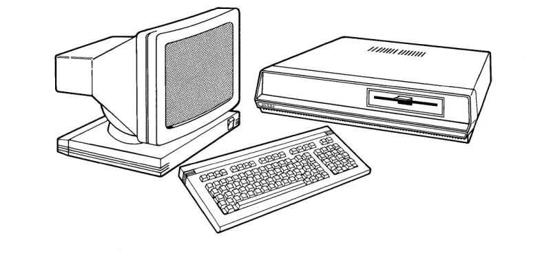
Al tos 486 System 1-1 Choosing a Location 2-2 486 Backpanel
2-2 Altos III Terminal Backpanel
2-3 Connecting the Keyboard to the Monitor 2-3 Connecting the Terminal Power Cord 2-4 Connecting the Terminal to the System 2-4 Connecting the System Power Cord 2-5 Rear Viewof the 486Systemwiththe
Cables Connected
3-2 Power Switches For System and Terminal 6-2 Diskette Handling
6-3 Inserting a Diskette
7-2 Wiring Diagram - 486 to Epson RX-80 (Serial)
7-3 Wiring Diagram - 486 to Epson MX-80 FIT (Serial)
Introduction
[image:6.540.95.487.315.504.2]Choosing A Location
1
1-2
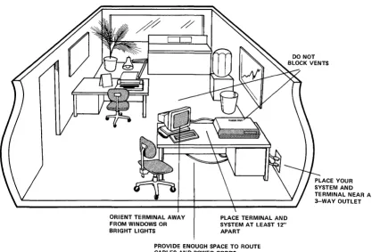
After unpacking your 486 and terminal, decide where you want to use your system. When choosing a location, consider these suggestions:
1. Choose a stable surface to hold your system and terminal. Make sure that the surface is large enough to provide 12" of distance between the system and the terminal.
2. Place your system and terminal near a 3 way power outlet.
3. Orient your terminal away from direct sunlight or strong room lights.
4. Provide enough space to route the cables and power cor ds.
ORIENT TERMINAL AWAY FROM WINDOWS OR BRIGHT LIGHTS
PLACE TERMINAL AND SYSTEM AT LEAST 12" APART
PROVIDE ENOUGH SPACE TO ROUTE CABLES AND POWER CORDS
Figure 2. Choosing a Location
[image:10.541.59.476.125.408.2]COftEftS
Setting Up Your System
2
CONNEC!'DIG '!BE KEYBOARD TO THE ImNITOR
CONNEcrIM; 'DIE TERMINAL P(MER CORD
2-2
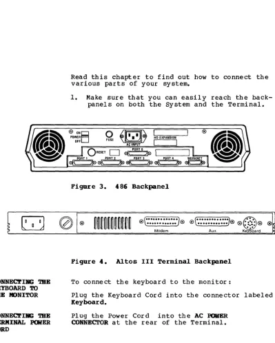
Read this chapter to find out how to connect the various parts of your system.
1. Make sure that you can easily reach the back-panels on both the System and the Terminal.
o
~Itl.
IJ\,
tD EXPANSIDN FUSE AC INPUT I IO
RESETD
~I PORT 5 L -_ _ _ - - 'PORT 1 PORT 2 PORT 3 PORT 4 WORKNET
~\ }~~\ }~~( )~a\ )~ ~
Figure 3. 486 Backpanel
,(
...
).®t··· ...
J@ ® \ ••••••••• ••• ,( ....•••..•... J® ), @ : :::: @ '~.", ®Aux. Ke" "~ard Modem
Figure 4. Altos III Terminal Backpanel
To connect the keyboard to the monitor:
Plug the Keyboard Cord into the connector labeled Keyboard.
[image:13.546.67.467.97.596.2]CONNECl'Ia; mE TBRIlllIAL TO SYSTEM
[image:14.548.171.448.83.354.2]Figure 5. Connecting the Keyboard to the Monitor
Figure 6. Connecting the Terminal Power Cord
NOTE
DO not pI ug the power cord into the wall outlet.
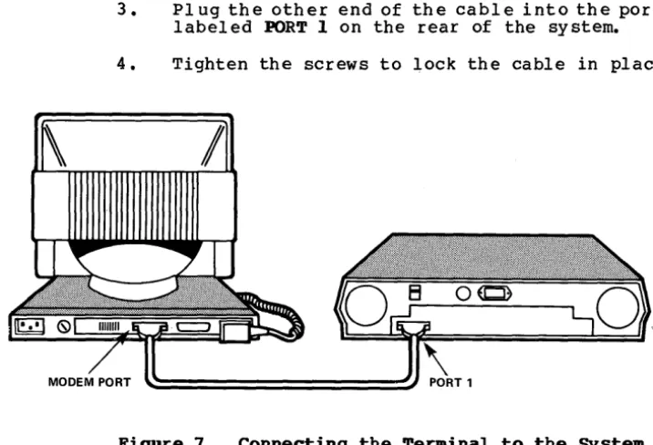
1. Plug one end of the interconnect cable into the connector labeled Mode. at the rear of the monitor.
CONNEC'.rDiIG TIlE
SYSTEM POWER
CORD
2-4
3. Plug the other end of the cable into the port labeled PORT 1 on the rear of the system.
[image:15.548.106.464.57.301.2]4. Tighten the screws to lock the cable in place.
Figure 7. Connecting the Terminal to the System
Plug the power cord into the AC IM~ receptacle at the rear of your system.
ACINPUT
Figure 8. Connecting the System Power Cord
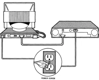
The drawing below shows how the cables are connected when you are finished.
[image:16.545.103.451.131.410.2]POWER CORDS
CONrEftS
Starting Your System
3
3-2 BEFORE YOU BEGIN
BEFORE YOU BEGIR
TURNIR; mE TERIIIIIAL ON
TORNIIIS mE
SYSTEM ON
3-2
[image:19.544.65.488.97.609.2]1. Make sure that the power switches for both the system and the terminal are in the OFF position.
Figure l~.
~
POWER SWITCH
PANEL BRIGHTNESS CONTROL
Power Switches For Systea and Terminal
2. PI ug the power cor ds f or the sy stem and the terminal into the wall outlets.
1. Turn the terminal on by pushing the top half of the ON/OFF switch. Listen for a short beep.
2. Watch for the cursor (small rectangular block) to appear in the upper left-hand corner of the screen. After about 30 seconds, if the cursor does not appear, turn the thumbwheel (located on the lower right corner of the screen) downward.
486 MONITOR VERSION Vl.0
> Power-up test ••• passed
> System configuration: Memory size (KB) 768kb Hard disk(s)=2
Floppy Drive(s): 1
PRESS ANY KEY TO INTERRUPT AUTO-BOOT >Booting from hard disk failed
>Select: [1] to boot from hard disk [2] to boot from floppy disk [3] to boot from WorkNet [4] to boot from Debugger
Enter option:
The system autoBatically verifies that the system is working properly.
If the system does not pass the power-up test the following message appears on the screen:
486 MONITOR VERSION Vl.0
> Power-up test ••• failed
<
>
> System configuration: Memory size (KB) = 768kb Hard disk(s)=2
Floppy Drive(s): 1
> Select: [1] to boot from hard disk [2] to boot from floppy disk [3] to boot from WorkNet [4] to boot from Debugger
>Enter option:
Problem Checkl ist
4
4-2
1. If the fan on the system is not running, check the following:
D Is the Power Cord pI ugged into the rear of the system and into the wall outlet?
D Check the wall outlet by pI ugging in a lamp.
D
Check the fuse by doing the following: D Set the Power Switch to OFF.D
Unplug the power cord from the wall outlet.Remove the fuse holder by inserting a screwdriver into the fuse holder slot and turning it counter-clockwise.
Inspect the fuse. It is defecti ve if the wire between the two metal caps is broken or no longer vi si bl e. Replace the fuse if necessary. Otherwise, reinsert the fuse holder into the rear panel and using the
screwdriver, turn itclockwise.
2. If nothing appears on the screen, check the following:
[J
Is the keyboard plugged into the Monitor?D
Is the cable between the terminal and the system secure at both ends?DIS the brightness control on the lower right corner of the screen rotated all the way down?
CAU'I'ION
Where Do You Go Next?
5
5-2 OPERATING SYSTEMS
5-2 ALTOS FAMILY OF RELATED MANUALS 5-2 DIAGNOSTIC MANUAL
5-2 SYSTEM REFERENCE MANUAL 5-2 MAINTENANCE MANUAL
OPERATIlIG SYSTEIIS
ALTOS FAMILY OF RELATED MARUALS
486 DIAGNOSTIC MAJJtJAL
486 SYSTEM
REFERENCE MABUAL
5-2
If you successfully started your 486 system, your
next step is to load the operating system, either XENIX or Concurrent CP/M. Refer to the Introduction to XERIX manual or the Introduction to Concurrent CP/M manual. These manuals introduce you to the basic principles of each operating system. They also contain installation instructions and information on how to use the Altos implementation of both systems.
There are additional manuals which will assist you in using your Altos 486 system.
The 486 Diagnostic Manoal comes with your 486 system. By using this manual with the diagnostic diskette, you can run a series of tests to pinpoint problems, should your system malfunction. The diag-nostic program also containsseveral utilities such as formatting and copying afloppy diskette.
The 486 System Reference Manoal also comes with your system. It covers the programmable
486 MADft'ERAllCE MANUAL
ALTOS III TERMINAL MAIftENAIlCE MANUAL
Tbe 486 Maintenance Manual (Part Number 690-15683-001) must be purchased separately from Altos. It is intended for technicians performing field repairs. The manual contains a detailed theory of operation, as well as troubleshooting, disassembly, reassembly and repair procedures.
The Altos III Terminal Maintenance Manual (Part Number 690-1574-001) must be purchased separately from Altos. It is intended for the technician and provides a detailed theory of operation,
COlftEftS
Handling Diskettes
6
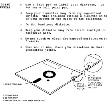
HANDLING DISKETTES
o Use a felt pen to label your diskette. Do Not use a ball point pen.
o Keep your diskettes away from any magnetized objects. This includes putting a diskette on top of your system or too close to the telephone.
o Do Not bend your diskette.
o Keep your diskette away from direct sunlight or excessi ve heat.
o Do Not touch or clean the exposed surfaces on the diskette.
o When not in use, store your diskettes in their protective jacket.
NOTE:
1. AVOID TOUCHING
IF NOTCH IS COVERED, YOU CANNOT WRITE DATA ON DISK
2. DO NOT BEND 3. DO NOT DROP
4. KEEP IN JACKET COVER WHEN NOT IN USE.
Figure 11. Diskette Handling
[image:31.545.92.467.211.572.2]PROTEC'.rIIiG YOUR DATA
IBSERTDIG A DISKETTE
The 5 1/4 inch diskettes that you will use with your system have a notch cut into the side.
You also receive silver pieces of tape for covering this notch.
When the notch is covered you cannot wr i te or
erase data on the diskette. This is known as write-protected.
When the notch is not covered you can write or erase data on the diskette. This is known as write-enabled.
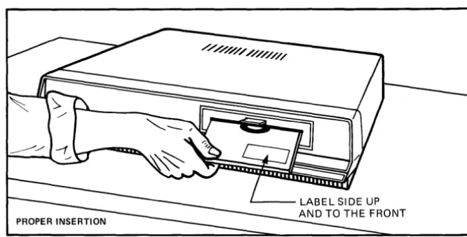
To insert a diskette:
Open the drive door by pressing the rectangular area below the slot.
With the manufacturer's label facing up and the notch to your left, gently insert the diskette into the drive until you hear a click. Close the door.
Figure 12. Inserting a Diskette
SAVIRG ORIGIRAL Always make copies of the original diskettes
[image:32.545.124.457.295.464.2]COftElft'S
Connecting A Printer And
7
Additional Terminals
7-2 CONNECTING A PRINTER
CONNEC!'UIG
A PRINTER
7-2
This chapter describes how to connect a printer and additional terminals to your 486 syste~
Connect your serial printer to BDRT 5 on the Altos 486 with a RS232C cable. This is an industry stan-dard cable and is readily available.
NOTE
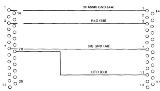
Epson RX-SI, MX-SI and Texas Instruments TI-S10
A special cable is required between the Altos 486 and these three printers. Figures 13, 14, and 15 illustrate the necessary wire connections.
ALTOS 486 EPSON RX-80 (Serial)
1 0-- CHASSIS GND (AA) 1
014
°
0 1400 20
3 0-=- RxD (BB) 3 0
o °0
0 0 00
00 00
7 0 0 SIG GND (AB)
°
00cJ~2~O~========~---~700
00 00
00 00
o 0 DTR (CD) 11
°
000 00
o 0 25 0025
13
0 130
[image:35.545.168.430.392.540.2]CORRECTIBG ADDITIONAL TBRIIIIlALS
ALTOS 486 EPSON MX80 FIT (Serial)
1 CHASSIS GND (AA) 1
OC514 ---~--~~~~---~o 0 14
2 ~ TxD(BA) 2 0
3
0-0
0 RxD (BB) 030
40 4 0
5
0
r;-oO
°0
~0 0 6~
7 ~ SIGNALGND (AB) 7 - 0 19
o
2....0
2000W 0
0 0 0 0
~ ~
~~
o 0 25 0 25
13
0 130 0
JUMPER
Figure 14. Wiring Diagram - 486 to Epson MX-SI (FIT Serial)
ALTOS 486 TI-810 (Serial)
10~ __________________________ C_HA_S_S_IS_G_N_D_(A_A_) ____ ~10
2 014 TxD (BA) 0 14
0 0 2 0
3
°
RxD (BB) 3 0o 00
0 0 0 0
0 0 50
6 0
7 0 0 SIG GND (AS)
8
7 0 JUMPER00-
20 200 0 8
0 0 0 0
0 0 0 0
OTR (CO) 11 0
o 0 ~---~OO
o 0 25 0 0 25
13
0 130
Figure 15. Wiring Diagram - 486 to TI-818 (Serial)
[image:36.540.136.450.46.416.2] [image:36.540.138.450.50.201.2]CONrEftS
Appendix A
Altos 486 Specifications
This appendix provides a general description of the 486. For more detailed specifications see the 486 Syste. Reference Manual.
A-2
SIZE
1 7 " (W) x 15 " (D) x 3 .5 " (H)
WEIGHT
20 Ibs.
REAR PABEL <DNNECrORS MID CONrROLS (See Figure 5) AC ON/OFF Switch
AC Power Receptacle Fuse Holder
Reset Button
Serial Ports (Numbered Connectors 1-5) WORKNET Port
BOWER SUPPLY IDENrIFICATION
lIS-vol t AC 230-volt AC MAXIMUM INPUT POWER
u.s.:
95 VAC to 130 VAC single phase EUROPE: 190 VAC to 260 VAC single phaseFUSE ftPE
BOKER DISSIPATION
180 watts
AMBIEft TEMPERATIDRE ~E
50 to 900 Fahrenheit
15 to 320 Centigrade
RELATIVE BUMIDI~ RABGE
20% to 80% Non-condensing
CPO
16-Bit
Altos 486
Backpanel, 2-2
Choosing a Location, 1-1 Power Cord, 2-2
Turning On, 3-1 Altos III Terminal
Backpanel, 2-1
Brightness Control, 3-2
Connecting the power cord, 2-2 Connecting to the System, 2-3 Positioning, 1-2
Power Switch, 3-2
Backpanel 486, 2-1
Altos III Terminal, 2-1 Brightness Control, 3-2
Cabling
Printers, 7-1 RS232C cable, 7-1
Terminal to System, 2-2 Choosing a Location, 1-1 Concurrent CP/M, 5-2
Diagnostics, 5-2 Diskettes
Handling, 6-2 Inserting, 6-2
Saving Originals, 6-2
Fuse, 4-2
Keyboard
Connecting to the Monitor, 2-2
Maintenance, 5-2
Monitor
Connecting to the Keyboard, 2-2
Operating Systems Xenix, 5-2
Concurrent CP/M, 5-2
Power Cord
System, 2-3 Terminal, 2-2 Power Switch
System, 3-3 Terminal, 3-3 Power Up Test
Failed, 3-4 Passed, 3-3 Printers
Connecting, 7-2 Epson RX-S0, 7-3 Epson MX-80, 7-3 TI-SI0, 7-3
Problem Checklist, 4-2
RS232C, 7-3
Specifications, A-I
Starting Your System, 3-2 System Reference Manual, 5-2
Terminal
Al tos II I
Brightness Control, 4-2
Connecting to the System, 2-3 Power Switch, 3-2
Connecting Additional, 7-2 Turning the System On, 3-2 Turning the Terminal On, 3-2 Xenix Operating System, 5-2
Warranty Information
Altos Computer Systems warrants each of its products to be free from defects in materials and workmanship for a period of 90 days from the date of purchase by the end user. During the warranty period, Altos, at its option, will repair or replace components in the products that prove to be defective at no charge other than shipping and handling, provided the product is returned to:
Altos Computer Systems 2641 Orchard Parkway San Jose, California 95134
This warranty will not be effective if, in the oplnlon of Altos Computer Systems, the Altos product has been damaged by accident, misuse, misapplications, or as a result of service or modifications by other than an authorized Altos service center.
THIS WARRANTY IS EXPRESSLY EXCLUSIVE AND IN LIEU OF ALL OTHER WARRANTIES OR GUARANTEES EITHER EXPRESSED OR IMPLIED, INCLUDING WARRANTIES OR GUARANTEES EITHER EXPRESSED OR IMPLIED, INCLUDING, BUT NOT LIMITED TO THE IMPLIED WARRANTIES OF MERCHANT-ABILITY AND FITNESS FOR A PARTICULAR PURPOSE. IN NO EVENT SHALL ALTOS BE LIABLE FOR LOST PROFITS, LOSS OF GOOD WILL, OR ANY OTHER SPECIAL OR CONSEQUENTIAL DAMAGES.
Return of the End-User Registration Card is required for this warranty to be valid. Warranty claims are void unless the End-User
ALms -486 SEftIBG UP GUIDB
READER COMMENT FORM
Altos Computer Systems 2641 Orchard Parkway
San Jose, CA 95134
This document has been prepared for use with your Altos Computer System. Should you find any errors or problems in the manual, or have any suggestions for improvement, please return this form to the ALTOS PUBLICATIONS DEPARTMENT. Do incl ude page number s or section numbers, where applicable.
System Model Number ____________________ _
Serial Number ________________ _
Document Title ____________________________________________________ __
Revision Number __________________________ Date ______________________ __
Name ______________________________________________________________ __
Company Name ______________________________________________________ __