I.
Introduction
D
uring the last 65 years when computer processing remained in its infancy, the application of computer processing could not be extended to visual recognition because it merely consisted of a simple input and output operation. Hence, computer vision and recognition represents one of the culminating achievements of the aforementioned research domain, although a huge challenge has yet to be overcome. Any area of computer processing research is geared toward mimicking human-like visual perception and interpretation to translate an image into recognizable objects [1]. Currently, in the wake of rigorous computer hardware and software advancements, image processing and recognition no longer remains as a mere theoretical possibility. Moreover, it is deemed as an essential advantage to incorporate such technologies into a variety of industrial enterprises, as in visual recognition systems for quality control and assessment, for instance, prior to public consumption[8][9]. Evidently, the application of the technology is in high demand in
the manufacture of mobile phones, compact cameras and robot soccer. In robot soccer, artificial vision processing plays a crucial role in recognizing goal posts, teammates, opponents and balls. Based on prior information, the above process is of great utility in localizing humanoid robots in field play to prevent rogue and random movements. In addition, it is indeed expedient for any robot to be able to recognize its location on a field when employing attacking or defending strategies. Based on the 2013 rules of the Robot Soccer competition, poles colored blue-yellow-blue on the left and yellow-blue-yellow-blue-yellow on the right, which functioned as landmarks, were set up outside the middle field to assist in robot self-localization on the field [5][16]. However, a different set of rules are currently in place whereby the poles are to be replaced with the goalpost as the landmark. Consequently, a serious challenge must be confronted as a result of the over- reliance on these poles as landmarks by the majority of preceding studies. This calls for a new localization technique that can substitute the missing poles at the middle of the field with goalposts as the reference points. One way to enable recognition of goalposts prior to localization is to consider prior information, namely the properties or features of the object to be recognized, including the shape, color, size and total number of corners.
Corner detection is the most used feature in the object recognition process, as evidenced by the range of corner detection techniques available for various applications [2][7]. Recently, various corner
Keywords
Analytic Geometry, Localization, Robotics, Single Camera, Visual Intelligence.
Abstract
In the humanoid competition field, identifying landmarks for localizing robots in a dynamic environment is of crucial importance. By convention, state-of-the-art humanoid vision systems rely on poles located outside the middle of the field as an indicator for generating landmarks. However, in compliance with the recent rules of Robocup, the middle pole has been discarded to deliberately provide less prior information for the humanoid vision system to strategize its winning tactics on the field. Previous localization method used middle poles as a landmark. Therefore, robot localization tasks should apply accurate corner and distance detection simultaneously to locate the positions of goalposts. State-of-the-art corner detection algorithms such as the Harris corner and mean projection transformation are excessively sensitive to image noise and suffer from high processing times. Moreover, despite their prevalence in robot motor log and fish-eye lens calibration for humanoid localization, current distance estimation techniques nonetheless remain highly dependent on multiple poles as vision landmarks, apart from being prone to huge localization errors. Thus, we propose a novel localization method consisting of a proposed corner extraction algorithm, namely, the contour intersection algorithm (CIA), and a distance estimation algorithm, namely, analytic geometric estimation (AGE), for efficiently identifying salient goalposts. At first, the proposed CIA algorithm, which is based on linear contour intersection using a projection matrix, is utilized to extract corners of a goalpost after performing an adaptive binarization process. Then, these extracted corner features are fed into our proposed AGE algorithm to estimate the real-word distance using analytic geometry methods. As a result, the proposed localization vision system and the state-of-the-art method obtained approximately 3-4 and 7-23 centimeter estimation errors, respectively. This demonstrates the capability of the proposed localization algorithm to outperform other methods, which renders it more effective in indoor task localization for further actions such as attack or defense strategies.
Humanoid Localization on Robocup Field using Corner
Intersection and Geometric Distance Estimation
M. N. Sudin
1, S. N. H. Sheikh Abdullah
1, M. F. Nasudin
2*
1
Center for Cyber Security, Faculty of Information System and Technology, Universiti Kebangsaan Malaysia, 43600 Bangi,
Selangor (Malaysia)
2
Center for Artificial Intelligence Technology, Faculty of Information System and Technology,
Universiti Kebangsaan Malaysia, 43600 Bangi, Selangor (Malaysia)
Received 18 February 2019 | Accepted 13 March 2019 | Published 9 April 2019
* Corresponding author.
E-mail addresses: [email protected] (M. N. Sudin), [email protected] (S. N. H. Sheikh Abdullah), mfn@ ukm.edu.my (M. F. Nasudin).
detection methods such as JUDOCA [13], CPDA [2], ANDD [19] and MPT [17] have been developed. Nonetheless, most of these techniques are very time consuming for merely extracting corners and are overly sensitive to the dynamics of the environment. Distance estimation processes for localization are in need of a new technique in response to the changes in the rules and to the loss of prior information while overcoming one of the biggest challenges in robot soccer: performing distance estimation processes with minimal equipment. Most state-of-the-art techniques produce non-negligible errors in distance estimation, which in turn necessitates an additional device, such as an odometer, to increase accuracy [15][13] or the use of an RGB-D camera with OpenPTrack [18][20]. Another approach used a simple localization with a camera [22][23][24]. With this approach, a 3 robot need to put extra sensor (such as wheel odometers and inertial navigation sensors) and making it accurate and desirable for our system. However, in our application, no extra sensors can be used other than camera based on Robocup rules. Thus, a new and improvised technique of visual recognition is to be developed with the objective of higher efficiency in distance estimation, lower processing time and greater responsiveness to the dynamics of the environment.
II.
The Proposed Method
There are two main tasks in developing a new vision system for a robot to self-localize in field play during robot soccer competitions. First, a technique to extract corner features is to be applied, followed by the use of these features to estimate distances between the robot and the goalpost as the main landmark. Fig. 1 shows the previous match rules.
Fig. 1. Robot soccer competition game play with middle pole as a landmark in 2012.
A. Line Intersection
The raw images suffer from superfluous information and dynamics. Accordingly, before a corner is extracted, the raw images must first be converted to a binary image containing only values of 0 and 1 [3] [4]. Because the testing data set is in grayscale, adaptive thresholding is used as a binarization method. Equations (1) and (2) show the binarization method:
(1)
(2) Based on Equation (1), f(x,y) is a pixel value in the raw images,
and f'(x,y) is a pixel value upon binarization. T(x,y) is a threshold value
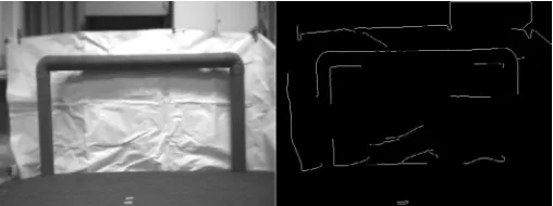
derived from the Gaussian equation for a distribution function for non-correlated variables with variations x and y having normal distributions for the same standard deviation. In this research, the threshold value is the middle value of the 3×3 neighboring pixels. Fig. 2 shows goal images before and after thresholding.
Fig. 2. (a) Grayscale image for goalpost; (b) Binary image for goalpost.
Upon applying the conversion method, the binary images must be analyzed pixel by pixel. Hence, square matrices (kernel) of size 3×3,5×5,8×8 and 11×11 are generated to process the binary images line by line. By using these kernels, the x and y corners will be extracted when the kernel processes the corners in the image. Four coordinates are recorded if the corner is detected, with two coordinates on the x – axis and two coordinates on the y - axis. The next equations show the selection process for the row and column selected by each kernel to generate the four coordinates in the kernel.
(3) Based on Equation (3), k is a row or column index for a kernel of size s,{3,5,8,11}, and a is a constant value {0,1,2,3} incremented by the kernel size. The blue line in Fig. 3 shows the horizontal and vertical lines chosen for each kernel size.
Fig. 3. Horizontal and vertical lines for each kernel.
Based on Fig. 3, if any part of the blue lines includes a white pixel (value of 1), then the coordinate of the pixel is recorded and processed when all four coordinates are recorded. The vertical blue line is utilized to obtain the coordinates from the horizontal contour, and the horizontal blue line is utilized to obtain the coordinates from the vertical contour. Equations (4) and (5) show the process of white pixel detection for each line assuming Pl for the horizontal contour and Pt for the vertical contour.
(4)
(5) After four coordinates are obtained, we can approximate the gradient value from both contours, namely, the vertical and horizontal contours. Then, using the gradient value from both contours, any intersection point from these contours can be assumed to be a corner. To extract the coordinates of the corner, linear equation theory and analytic geometry theory are applied by manipulating all four coordinates obtained previously.
(6)
We assume that the first point is on the horizontal contour, Pl1(x,y), and that the second point is on the horizontal contour, Pl2(x,y), on the same contour line; hence, they share the same gradient value, and ml and the intersection points are at y-axis, cl . This is also the case
with the vertical contour, where the first point, Pt1(x,y), and the second
point, Pt2(x,y), are assumed to be on the same vertical contour and
share the same gradient value, mt , and intersection point on the y-axis, ct . To determine the gradient value for each contour, Equations (6) and (7) were placed into a new form.
(8)
(9) Once the gradient value is obtained, the value of the intersection point on the y-axis for both contours, horizontal and vertical, can be obtained using the following equations.
(10)
(11) When all the values are obtained, the intersection between the vertical contour and the horizontal contour is classified as a corner. If the vertical and horizontal contours are on the same contour, then the gradient value is equal to zero. Accordingly, if no corner is detected in the current kernel, then it will move on to the next kernel. The equations used to acquire the corner are defined below.
(12)
(13) Finally, the corner coordinates are recorded and marked for further processing by the robot during localization. Fig. 4 shows the process for each kernel. The blue points represent the detected corner, and the red pixels represent the four pixels obtained on the vertical and horizontal contours.
Fig. 4. Corner detection performed using line intersections. Two red pixels in
Pt(x,y) and two yellow pixels in Pl(x,y) are used as coordinates to find the
intersection point (blue pixel) of two green lines, mt and ml.
B. Analytic Geometry for Distance Estimation
In previous studies on camera calibration, using prior information such as the focal length of the camera, constant x and y values were extracted [12][13][14][20]. All these values can be obtained as intrinsic
camera values. Aside from these intrinsic values, extrinsic values are also present and are of great utility in reducing distortion in an image captured by a camera using a convex lens. To use analytical geometry approaches, the produced image must closely resemble that in real time
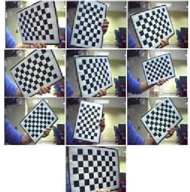
[12]. The distortion of an image produces errors in distance estimation. To address convex-lens-induced distortions in images, 10 images with a chessboard were captured at random orientations to determine the distortion difference relative to the real time imagery as shown in Fig. 5.
Fig. 5. Self-collection data from MVLab used to obtain the intrinsic and extrinsic values.
Based on Zhang’s methods [21], the intrinsic, extrinsic, and pinhole values of the camera are extracted and processed. These processes only need to be performed once as long as the same camera and lens are used. The equation shows the data value and the intrinsic value obtained from the first calibration. Given that R is an image rotation and T is an image transformation, we have
(14) Upon repairing the image, some of the features of the goal post are extracted. Based on Robocup rules, the pole had a height of 10 cm and a width of 60 cm. The goalpost should be yellow and blue only, and the shape of the goal should be rigid and hard. Therefore, the color and shape of the goal post are suitable for extraction. To extract the color, HSV color range values are considered due to their higher robustness to light intensity variations compared to the RGB color range. RGB colors are more sensitive to even the slightest change in color. Moreover, RGB color ranges produce more noise in the data and hence this makes difficult to clearly distinguish the goal post shape
[10]. Fig. 6 shows the color of the goal post extracted using the HSV color range.
After the color is extracted, the shape of the goal was determined. The purpose of the shape detection is to ensure that only the complete shape of the goal is input to the next process. If the camera is too close to the goal post, the shape of the goal post becomes larger than the camera frame size, and vice versa. An improper goal post size renders the next process more cumbersome and prone to error. Hence, measurements such as density, elongation, roughness, convexity, height and width were defined beforehand. If the goalpost does not meet the predefined criteria, then it is considered to be incomplete, resulting in the termination of the process. In turn, a re-calibration of the camera and redefinition of the color have to be performed. Fig. 7 shows an incomplete goal post.
Fig. 7. Example of an incomplete goal shape from self-collection data set in MVLab.
If the goal shape can be viewed completely, the goal corner will be extracted using the above corner detection method. The purpose of this action is to compare and relate actual and virtual distances between two corners. According to Siswantoro et al. [14], the object size in a camera image is relatively equivalent to the actual object size in real time. Using a similar approach, distance estimation can be performed after considering the relative factor that causes differences in measurement in real time and in virtual images. The relation between images from the camera and those obtained in real time can be determined via prior camera calibration along with the intrinsic values. The equation below shows the relation between the image camera coordinates and the real-time coordinates.
(15) In Equation (15), the left-hand side represents the coordinates in the image plane, and the right-hand side represents rotation and transformation coordinates in the camera plane. The values of fx and
fy are the focal length of the lens on the x and y axis. Cx , Cy and Zc are
confession numbers from the intrinsic values. For distance estimation, the image coordinate should be obtained beforehand so that it can subsequently be related to actual parameters. The next equations demonstrate how the method obtains the coordinates in the camera plane.
(16)
(17)
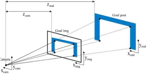
(18) As stated previously, the goal post is taken as the main landmark for parameter assessment. For the distance estimation process, the height of the left and right goal posts are selected as a reference to compare with the actual height and image height. Fig. 8 shows the location of the camera coordinate, image coordinate and real-time coordinate.
Fig. 8. Relation between camera, image and real-time coordinate.
Based on Fig. 8, it is observed that the goal post image is reduced in size compared to the real goalpost. By relating the camera coordinate to the real coordinate, the value of Zcam becomes a scaled version of Zreal, which represents the actual distance between the camera and the
goal post. Hence, the distance estimation can be performed using this equation,
(19) where l is the distance between two points in an image, a is the value of Zcam, L is an actual two-point distance in real time of the goalpost, and a + b is a Zreal or the estimated distance. In this paper, l and L are representing two points as the right and left-hand sides of the goalpost. The calculation is performed twice to increase the accuracy of the estimated distance.
III.
Result and Discussion
One of the objectives of this research was to develop a new corner detection technique for goalpost corner extraction. The technique must be efficient, robust and less time consuming to process. Accordingly, in assessing the performance, the proposed corner detection is to be compared with state-of-the-art corner detection methods such as JUDOCA [13], CPDA [2], ANDD [19] and MPT [17]. A common test for corner detection is the localization error test, which attempts to obtain the average error for each point within 3 pixels in each corner in an image. The smaller the localization error produced by a technique, the more accurately the technique can detect corners.
(20) Based on Equation (20), xoi and yoi are the original coordinates of a
corner in an image, and xti and yti are detected coordinates at the current pointi. Nr is the total number of corners detected in the same image. The benchmark data set for corner detection from Awrangjeb research [2]
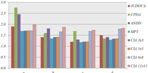
was commonly used to measure accuracy as show in Fig. 9 and Fig. 10 shows the results when we apply localization error to the current state-of-the-art corner detection methods.
Fig. 10. The localization errors for JUDDOCA, CPDA, ANDD, MPT and our proposed CIA corner detection techniques when the kernel size is 3x3, 5x5, 8x8 and 11x11.
Based on Fig. 10, MPT [17] yields the best results by providing the lowest localization average error across the entire dataset, followed by the line intersection for the 5×5 kernel, JUDOCA, 3×3 kernel, 8×8 kernel, ANDD, CPDA and 11 × 11 kernel. The MPT method obtains the highest accuracy for extracting corners from images; however, the process requires approximately 2 seconds for each picture, a severe disadvantage for Robocup competitions. Hence, the line intersection method is selected because it is the second-most accurate method and requires only 0.049 seconds for extracting a corner.
For the distance estimation test, the proposed method is compared with the dual camera stereo vision method for the image quality assessment [15]. Fig. 11 shows the test setup on the robot. The use of a stereo camera is advantageous due to its similarity to human vision. The test was performed three times during actual game play at distances between 350-190 cm, each 10 cm with straight vision to the landmark (0 degree), 20 degrees to the left of the landmark, and 20 degrees to the right of the landmark to represent vision from various sides of the field. Table I shows a comparison of the results.
Fig. 11. Wireless camera attached to a robot for the distance estimation test.
TABLE I. Difference Between Stereo and Single Camera Via Proposed AGE Method
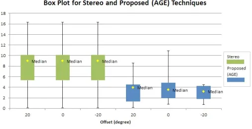
Based on Fig. 12, the field simulation shows the actual radial distance (black line) from the center of the goal post and the goal post clearly observed by the camera on the robot. In Table I, both techniques (stereo and proposed) are able to estimate the distance the around field with straight to the landmark and 20 degreed offset to the left and right. On average, for each angle, the stereo technique produces constant mean errors of approximately 7.980 cm, demonstrating that the technique was robust and stable at any angle. The proposed technique produces inconsistent mean distance errors for certain angles. However, the margin errors remain less than those of the stereo technique. Overall, in distance estimation, the AGE technique produces an improved accuracy of 4.322 cm compared to the stereo-camera-based technique according to the summary in Table II. Concerning processing time, the AGE technique requires 0.54672 milliseconds to estimate the distance based on Fig. 13, whereas in Fig. 14, the error percentage is initially large, wherein the proximity to the landmark is the closest but undergoes substantial decrements as the distance increases. Summarizing, Fig.15 shows that the stereo technique (green) produces huge min and max error values but produces consistent median errors at any angle given; meanwhile, the AGE technique produces smaller min and max error values but does not produce very consistent errors at some offsets. It addition, the AGE technique is less accurate for straight lines, demonstrated by its larger error range compared to the offset value; however, the error is still small compared to the stereo technique. The error obtained using the AGE technique may be smaller because this technique only uses a single image from a single camera, whereas the stereo camera technique must patch together both images from both cameras.
Fig. 12. The actual distance (black line) and distance estimation simulator
results (i) based on images captured by our humanoid robot at (ii)+20◦, (iii) 0◦ and (iv) -20◦. The red dot in the simulator represents the proposed detected point
based on our proposed (AGE) technique from a radial distance of a) 200 cm b) 250 cm c) 300 cm and d) 350 cm.
Fig. 13. Time required for proposed method (AGE) to estimate distance.
Fig. 14. Fluctuating relation between error and distance produced by both methods (AGE & stereo).
Fig. 15. Box plot for stereo and proposed (AGE) technique.
Furthermore, our proposed AGE method is simple and practical because it only uses a predetermined camera information and rules given. Considering those steps, this technique is more desirable to incorporate into the Robocup competition due to its minimal error in robot localization.
IV.
Limitations and Conclusions
Having performed the test, it is reassuring to conclude that this technique provides highly accurate corner detection and distance estimation compared with the other techniques. This evidently attests to the capability of the proposed technique in surmounting the most persistent predicament of object recognition at a significantly reduced execution time. However, this method continues to face a few setbacks, wherein this technique is unable to estimate distances of less than 190 cm due to the rather enlarged size of the goalpost image relative to the camera frame. This results in the incomplete detection of the shape of the goal post. Despite that, localization remains applicable at other areas within 8.0 meters, making it suitable for competition because of its accuracy, speed and robustness.
Acknowledgment
This research was funded by an FRGS/1/2014/CT07/UKM/02/5 grant entitled Overlapped Irregular Shape Descriptor based on Non-Linear Approach and AP-2017-005/2 grant entitled Using STEM Data Through Smart Self-Crime Prevention at Schools for Open Data
Readiness. We would like to thank Zamalah: Fellowship at Universiti Kebangsaan Malaysia (UKM).
References
[1] Nur Ariffin M. Z. 2013. Incorporating Camshift Algorithm and Support Vector Machine for Object Tracking. Master’s Thesis in Universiti Kebangsaan Malaysia.
[2] Awrangjeb, M. Lu, G. 2008. Robust image corner detection based on the chord-to-point distance accumulation technique. Multimedia, IEEE Transactions on. 10(6): 1059-1072.
[3] Birchfield, S. T. Rangarajan, S. 2005. Spatiograms versus histograms for region-based tracking. IEEE Computer Society Conference on Computer Vision and Pattern Recognition. 2: 1710-1714.
[4] Birchfield, S. T. Rangarajan, S. 2007. Spatial histogram for region-base tracking. Electronics and Telecommunications Research Institute (ETRI) Journal. 29(5): 697-699.
[5] Tian, B., Ng, C. L. Chew C. M. 2010. Self-localization of humanoid robots with fish-eye lens in a soccer field. Robotics Automation and Mechatronics (RAM), 2010 IEEE Conference on, pp. 522-527.
[6] Bouthemy, P. Francois, E. 1993. Motion segmentation and qualitative dynamic scene analysis from an image sequence. International Journal of Computer Vision. 10(2): 157-182.
[7] Bowyer, K., Kranenburg, C., Dougherty, S. 1999. Edge detector evaluation using empirical ROC curves. Computer Vision and Pattern Recognition, IEEE Computer Society Conference on. 1: 354-359.
[8] Bradski, G. R. Kaehler, A. 2008. Learning OpenCV: Computer Vision with the OpenCV Library. California: OReilly Media Inc.
[9] Bradski, G. R. 1998. Computer vision, face tracking for use in perceptual user interface. Intel Technology Journal. 2(2): 12-21.
[10] Chen, W., Shi, Y. Q. Xuan, G. 2007. Identifying computer graphics using
HSV colour model and statistical moments of characteristic functions. Proceeding of IEEE International Conference on Multimedia and Expo, hlm. 1123-1126.
[11] Cheng, Y. 1995. Meanshift, mode seeking and clustering. IEEE Transaction
on Pattern Analysis and Machine Intelligence. 17(8): 790-799.
[12] Davison A. J. 2003. Real-time simultaneous localisation and mapping
with a single camera. Proceedings. Ninth IEEE International Conference on Computer Vision, vol. 2, pp. 1403-1410.
[13] Elias, R. Laganiere, R. 2012. JUDOCA: JUnction Detection Operator
Based on Circumferential Anchors. Image Processing, IEEE Transactions on, Vol. 21, no. 4, pp. 2109-2118.
[14] Siswantoro, J, Prabuwono, AS Abdullah, A 2013. ’Real World Coordinate
from Image Coordinate Using Single Calibrated Camera Based on Analytic Geometry’. in Communications in Computer and Information Science. vol. 378 CCIS, Springer Verlag, pp. 1-11, 2nd International Multi-Conference on Artificial Intelligence Technology, M-CAIT 2013, Shah Alam, 28-29 Ogos., 10.1007/978-3-642-40567-9-1.
[15] Pirahansiah, F.; Abdullah, S.N.H.S.; Sahran, S.,” Camera calibration for
multi-modal robot vision based on image quality assessment,” in Control Conference (ASCC), 2015 10th Asian, pp.1-6, May 31 2015-June 3 2015 doi: 10.1109/ASCC.2015.7360336.
[16] Jens-Steffen Gutmann, Dhiraj Goel, Philip Fong, Mario E. Munich,
Extensions to vector field SLAM for large environments, Robotics and Autonomous Systems, vol. 62, no. 9, September 2014, pp. 1248-1258, ISSN 0921-8890, http://dx.doi.org/10.1016/j.robot.2014.03.021.
[17] Kahaki, Seyed Mostafa Mousavi, Md Jan Nordin, and Amir Hossein
Ashtari. ”ContourBased Corner Detection and Classification by Using Mean Projection Transform.” Sensors 14.3 (2014): 4126-4143.
[18] Matteo Munaro, Filippo Basso, Emanuele Menegatti, OpenPTrack:
Open source multi-camera calibration and people tracking for RGB-D camera networks, Robotics and Autonomous Systems, vol. 75, Part B, January 2016, pp. 525-538, ISSN 0921-8890, http://dx.doi.org/10.1016/j. robot.2015.10.004.
[19] Shui, P. Zhang, W. 2013. Corner detection and classification using
anisotropic directional derivative representations. Image Processing, IEEE Transactions on. 22(8): 3204-3218.
[20] Xiang Gao, Tao Zhang, Robust RGB-D simultaneous localization
org/10.1016/j.robot.2015.03.007.
[21] Zhang, Z. 2000. A flexible new technique for camera calibration. IEEE
Transactions on Pattern Analysis and Machine Intelligence, vol. 22, no. 11, pp. 1330-1334.
[22] P. An, Y. Liu, W. Zhang and Z. Jin, “Vision-Based Simultaneous
Localization and Mapping on Lunar Rover,” 2018 IEEE 3rd International Conference on Image, Vision and Computing (ICIVC), Chongqing, 2018, pp. 487-493. doi: 10.1109/ICIVC.2018.8492755.
[23] V. P. Kirnos, V. A. Kokovkina, V. A. Antipov and A. L. Priorov,
“Simultaneous Localization and Mapping Using the Support Image Base Algorithm,” 2018 Systems of Signal Synchronization, Generating and Processing in Telecommunications (SYNCHROINFO), Minsk, 2018, pp. 1-4. doi: 10.1109/SYNCHROINFO.2018.8456965.
[24] X. Guo, S. Zhu, L. Li, F. Hu and N. Ansari, “Accurate WiFi Localization
by Unsupervised Fusion of Extended Candidate Location Set,” in IEEE Internet of Things Journal. doi: 10.1109/JIOT.2018.2870659.
Siti Norul Huda Sheikh Abdullah
Received her first Degree in Computing at University
of Manchester Institute of Science and Technology, United Kingdom. She furthered her master study in the
area of Artificial Intelligence in Universiti Kebangsaan
Malaysia. Later, she continued her Phd Study in the area of Computer Vision at Faculty of Electrical Engineering, Universiti Teknologi Malaysia. Starting the career, she involved in conducting several national and international activities such as Royal Police of Malaysia, Cyber Security Malaysia, Cyber Security Academia Malaysia, Federation of International RobotSoccer Association (FIRA), Asian
Foundation, Global Ace Professional Certification Scheme, MIAMI, MACE
and IDB Alumni. She is now holding a post as the Chairperson of Center for Cyber Security. Her research focuses are Digital Forensics, Pattern Recognition, and Computer Vision Surveillance System. She has published two books entitled “Pengecaman Pola” or “Pattern Recognition” and “Computational Intelligence for Data Science Application” and more than 50 and 100 of journal and conferences manuscripts correspondingly.
Muhammad Nuruddin bin Sudin
First Degree in Computer Science major in Artificial
Intelligence at The National University of Malaysia (UKM), Malaysia. He furthered his master study in the Robotic area in the same university. Runner up in Robot Soccer Worldcup competition under FIRA in 2012 and become a winner in 2013 for 5v5 mirosot category. Currently, he continued his Phd Study in the area of Cyber Security at Faculty of Information Science and Technology, UKM. His research focuses
are Pattern Recognition, Robotic, Artificial Intelligence and Digital Forensics.
Mohammad Faidzul bin Nasrudin
He is an associate professor at the Faculty of Information Science and Technology, Universiti Kebangsaan Malaysia
(UKM) and an active researcher at the Center for Artificial
Intelligence Technology (CAIT), UKM. He obtained his Bachelor of Business Administration degree majoring in Computer Information System at the Western Michigan University, USA. He received a master’s from UKM and
a doctorate in Artificial Intelligence by joining the Malaysia - Imperial College