http://ijeas.truescholar.org
45
MITIGATION OF CORE AND WINDAGE LOSSES IN A SYNCHRONOUS
GENERATOR FOR IMPROVED PERFORMANCE
M. Olubiwe
1, L. Uzoechi
2, D.C. Nwagbara
3Department of Electrical and Electronic Engineering,
Federal University of Technology,
Owerri, Nigeria.
Corresponding Author:
M. Olubiwe
__________________________________________________________________________________________
ABSTRACT
Losses in motors and generators have become a source of concern to machine designers and fabricators. Performance of these machines depend largely on the different losses that results in the course of the machine operations. This research is tailored on the mitigation of these losses in synchronous generator. The objective of this research, is to study how windage and core losses in synchronous generator can be mitigated and improve overall engine efficiency. The method adopted is the modeling and simulation of a synchronous generator using MATLAB® and Simulink® to know the effect of core and windage losses. When the reactive power generated before mitigation and after mitigation of the losses, were simulated , the result showed that reactive power generated with losses was 0.0041Pu and after mitigation it was 0.0095Pu. Also when real power was simulated before and after mitigation, the result showed -0.11Pu and 0.17 Pu respectively. This research also proffers economical ways in which open-circuit or no-load losses can be significantly reduced, without compromising generator‟s efficiency.
© Ideal True Scholar
KEYWORDS: Seasonal, Cyclical, Irregular, Trend, Fluctuations, Cereal grains
__________________________________________________________________________________ INTRODUCTION
The use of machines has become a central and integral part of every being, or group of beings, ranging from heavy machinery, be it in the field of automobiles, aeronautics, motors, high and low powered generators, to basic human amenities such as fans, grinders, etc. In all these rotating devices, there exist some fundamental technicalities, which care must be taken to improve efficiency and overall performance of such a device. This research critically studied, analyzed, and proffer ways to ensure the mitigation of core and windage losses to improve shaft torque of a synchronous generator, to reduce the energy loss due to heat in the core, thus reducing the working temperature of the system. Reducing Engine downtime due to increased maintenance schedule and improve overall engine efficiency mathlab software was used for the simulation. These losses include copper losses, eddy current losses in the generator windings, hysteresis losses, etc.
A synchronous machine is an AC rotating machine whose speed under steady state condition is proportional to the frequency of the current in its armature. The magnetic field created by the armature currents rotates at the same speed as that created by the field current on the rotor, which is rotating at the synchronous speed, and this also produce a steady torque. (The global journals, 2014)
Synchronous machines are commonly used as generators especially for large power systems and Because the rotor speed is proportional to the frequency of excitation, synchronous motors can be used in situations where constant speed drive is required. Since the reactive power generated by a synchronous machine can be adjusted by controlling the magnitude of the rotor field current, unloaded synchronous machines are also often installed in power systems solely for power factor correction or for control of reactive kVA flow. Such machines, known as synchronous condensers, may be more economical in the large sizes than static capacitors. (Marubun, 2009)
46
and speed and subtracting windage and bearing losses from the aggregate open circuit losses.
Losses in a Synchronous Electrical Machine: Understanding and minimizing the losses of electric machines are critical to maximize power density and minimize the consumption of fuel. The losses of an electric machine can be categorized as load independent or dependent.
(A) Load independent or open circuit losses consist of core and mechanical losses:
Core loss consists of:
(i) Hysteresis losses. Material hysteresis losses are affected by the strength of the field, material metallurgy, and increases directly with frequency. They represent the energy required to reorient the magnetic domains during each cycle of alternating current. (Marubun, 2009)
(ii) Eddy current losses induced in the machine‟s iron core due to the presence of an alternating magnetic field. Eddy currents induced in the core are affected by lamination thickness and increase with the square of frequency.
Mechanical losses include windage and bearing friction losses. Windage loss is due to the frictional drag on the rotor due to the presence of air within the air gap. Windage loss is affected by the properties of the gas or fluid surrounding the rotor, machine geometry, surface roughness, and increases with the cube of rotor speed. Due to the cubic relationship with speed, windage is an important loss to manage in the design of high speed machines.
(B) Load dependent or short circuit losses are: (i) Copper losses
(ii) Stray load losses: The stray losses include a. Winding eddy current losses.
b. Higher order harmonics in the air gap. c. High frequency rotor and stator surface losses. d. Tooth pulsation losses.
(C) Any losses not accounted above.
Ucalgary, 2007 Showed that understanding and minimizing the losses of electric machines are critical to maximize power density and minimize the consumption of fuel. As surface speeds of electrical machinery increase to meet ever more demanding application requirements, windage power losses due to shearing of air (or other process fluid) between the rotor and stator take on an increasingly significant role. Windage is generally defined as the loss due to viscous shear and aerodynamic effects between the rotor and stator or in other words “the loss generated by the friction force between the rotor and the air”. Windage losses also contribute to higher operating temperatures which must be mitigated. Historically, these losses have not received a great deal of research attention. Common approaches include making the rotor and stator surfaces as smooth as possible,
keeping the rotor-stator gap as large as practical without compromising electrical efficiency, and simply accepting whatever losses that are present. (Vrancrik, 1968), developed a method of predicting the windage loss of rotating electrical machines operating in various gases under different pressures and temperatures. An equation was developed for a cylindrical rotor and modified by empirical relations to take into account the effects of the salient poles and shrouds of the homopolar inductor alternator. The effect of the gap length was also briefly studied. The windage loss for a shrouded homopolar inductor alternator was calculated by these equations and compared with the experimental results obtained at the NASA Lewis Research Center. The agreement was within 10 percent for a range of pressure from standard atmospheric to 40 psi. The empirical formula expressing the hysteresis loss per unit volume (Ph(W/m3)) in terms of the maximum flux
density (B (T)) and frequency (f(Hz)) was developed by Steinmetz (Hamdi, 1994). (Slemon, 2003) emphasized on the term “eddy current” which refers to circulating electric currents that are induced in a sheet of a conducting material when it is subjected to alternating magnetic field. These eddy currents produce power that is dissipated as heat. The eddy current loss per unit volume (Pe(W/m3)), at
frequencies which are low enough for the inductive effects to be neglected, (de Jong, 1989) showed the relevant equations
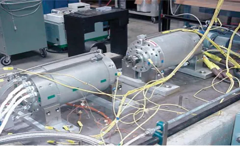
The windage loss generated in the clearance between a rotating cylinder and a stationary cylinder with homogenous laminar flow (no axial flow) was estimated from set of equations in (Vrancrik, 1968) Xdot Engineering and Analysis, along with Computer Aided Engineering Associates, (WWW.XdotEA) have recently completed a two year Phase II Small Business Innovation Research (SBIR) effort funded by the US Air Force to look at these losses in more detail. (Huynh, 2009) conducted a back to back test used to verify alternator losses and operating efficiency, which included two identical machines coupled together, with one operating as a motor, and the other as a generator, or load.
47
By measuring the input power to the motor and the output power from the generator, the total losses of the system were measured. The Spin-down test was also carried out to measure the damping torque, which involved the measurement of the initial speed versus time duration of the rotor from the initial speed to fully stop.
Stone, 2009 enumerated recent problems experienced with motor and generator windings, which include partial discharge problems, stator core, stator winding, rotor winding problems, and adequate measures employed by manufacturers to tackle this problems.
There were a number of factors that made the analytical prediction of the core losses difficult:
The relevant material properties were not well characterized at high frequency operation. Yet in a high frequency application, the core losses are unlikely to be negligible since the eddy current loss varies as the square of the frequency and the hysteresis loss varies in direct proportion to frequency
Core losses change due to armature MMF presence
The use of novel materials that are often not well characterized operating profiles that aren‟t compatible with the empirical data, validated models, or experience found with more conventional designs. (Chee mun-ong,1998).
The primary aim of every engineering firm/establishment is to produce a certain required output with minimum effort and resources. This has resulted in pressure on machine designers to reduce manufacturing cost. Some of these methods employed to accomplish this include. (Prabha, 1994) • Reducing the conductor cross section
• Reducing the insulation thickness
• Reducing the amount of steel core material
• Developing manufacturing methods that result in less time to manufacture.
Each of these methods tends to increase the operating temperature of the windings or put additional voltage stress on the electrical insulation.
PROBLEM STATEMENT
Generator‟s effeiciency has become a critical issues or concern to both manufacturers and operators or end-usres. Efficiency of machines depend largely on the reduction of losses. Generators are dynamically inclined in nature and this contributes on the losses incurred during operation. These losses ranges from Windage, core etc hence the need to mitigate them.
SIGNIFICANTS OF THE STUDY
Reduction in the efficiency in the performance of the generator, add operational cost to the overall cost. If the machine performance is optimum, credits goes to the manufacturer and the vendors, so eliminating factors that could reduce the effectiveness and performance of the machine is an important strategy. This is why the mitigation of the losses in synchronous generator is important.
SCOPE OF THE STUDY
The scope of this study is to study how windage and core losses could be mitigated in a synchronous generator.
METHODOLOGY
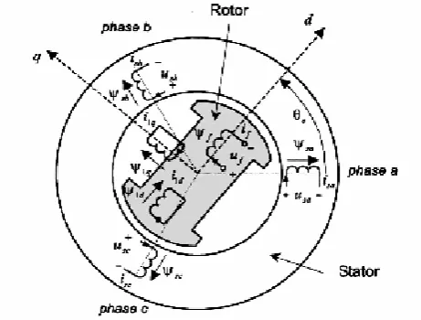
To properly simulate a machine, we need to have a model and accurate parameters for the model. In essence, there are two aspects that need to be modeled: the mechanical and the electromagnetic part. From a modeling point of view, all synchronous generators have similar representations. They differ only with respect to some model parameters. Because the round-rotor synchronous generator is used for this study, Damper windings are real or fictitious that can be used to represent, for example, the damping effects of eddy currents in the machine. In Fig. 2, one damper winding is located along the direct-axis, and one along the quadrature-axis.
Although the rotor may have only one physical identifiable field winding, additional windings are often used to represent the damper windings and effects of current flow in the rotor iron. For the salient pole rotor machine, usually two such additional windings are used, one on the d-axis, and the other on the q-axis. Damper windings in the equivalent machine model can be used to represent the damping effects of eddy currents in the solid iron portion of the rotor poles. (Chee mun-ong, 2009.)
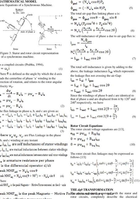
48 MATHEMATICAL MODEL
Basic Equations of a Synchronous Machine.
As a coupled circuits (Prabha, 1994),
(1)
Where is defined as the angle by which the d-axis leads the centerline of phase „a‟ winding in the direction of rotation, and relates to the rotor angular velocity
(2)
The flux linkage in phase a, b, and c are given as:
(3) , , , are Flux Linkage in the phase
a,b, and c winding at any instant
(4)
Where
Air-Gap fluxes per pole along the two axes are;
(5)
The total air-gap flux linking phase a is:
(6)
The self-inductance of phase a due to air-gap flux is:
(7)
The total self-inductance is given by adding to the above, the leakage inductance which represents the leakage flux not crossing the air-Gap:
(8)
Since the windings of phase b and c are identical to that of phase a and are displaced from it by 1200 and 2400 respectively, we have
(9)
Rotor Circuit Equations
The rotor circuit voltage equations are [13],
(10)
The rotor circuit flux linkages may be expressed as follows [13]:
(11)
THE dq0 TRANSFORMATION
The above equations associated with the stator and rotor circuits, completely describe the electrical characteristics of a synchronous machine. However, these equations contain inductance terms which vary with angle, which in turn varies with time. To reduce the complexity in solving machine and power Figure 3: Stator and rotor circuit representation
49
problems, the dq0 transform is implemented, leading to a clearer physical system.
The stator phase currents can be transformed as (Prabha, 1994):
(12)
For balanced Conditions,
(13)
Hence,
(14)
Also,
And
(15)
The transformation from the abc phase variables to the dq0 variables can be written in the following matrix form:
(16)
With the inverse transform given by:
(17)
Using the expression for and
Transforming the flux linkages and current into dq0 components, we obtain:
(18)
And the new inductances, defined as
(19)
The flux linkage equations becomes:
(20)
Substituting the expressions for and into
equation (17), the rotor flux linkages in the dq0 components gives:
(21)
The stator voltage equations in dq0 components are represented as:
(22)
Where the angle , is defined as between the axis of
phase a and the d-axis. The term represents the
angular velocity of the rotor.
Electrical Power and Torque
The instantaneous three phase power output of the stator is given as
(23) Eliminating phase voltages and currents in terms of dq0 components, we have
(24)
Under balanced operation, hence, the expression for power is give by:
(25)
Representing the voltage components in terms of flux linkages and currents, by recognizing as rotor
speed , and rearranging, we have
(26)
= (Rate of change of armature magnetic energy+ (power transferred across the air-gap) – armature resistance loss).
Air-Gap Torque is given as
=
50
When using a two stage transformation between abc and qd0 variables, the cosθr(t) and sinθr(t) terms are
generated by a variable-frequency oscillator. The transformation of the dq0 rotor reference currents back to the abc stator currents are performed inside the qdr to abc block. Since the full qd0 model already has damper windings included, the damping coefficient Dω is used to represent the damping from
windage and friction on the rotor.
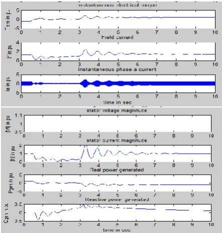
Simulated Results
By implementing the d-axis and q-axis reactance, and stator winding resistances from table 1, the following results were obtained.
Figure 4: Impedance Plot of various generator characteristics
By varying the windage and friction damping coefficient {i.e. assuming homogeneous laminar flow of fluid (Dω = 0)}, and a corresponding decrease of the d-axis, q-axis reactance, and stator winding resistance by 40% we obtain the following:
Figure 5: Plot of Mitigated generator characteristics vs. time
Table1: Real Power Generated at various time intervals
Figure 6: Graph of lines of Best fit showing real power Generated vs. time
Time(s) Real Power Generated PU (with Losses)
Real power Generated PU (Mitigated Losses)
0 1 1
1 -1 0
2 -0.5 0
3 0 0
4 -2 -1
5 -1 -1
6 -1 -1
7 -1 -1
8 -1 -1
9 -1 -1
10 -1 -1
51
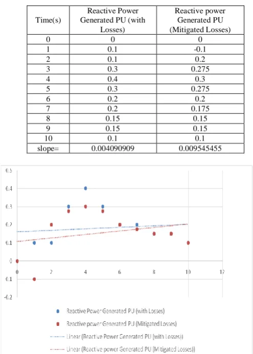
Table. 2: Reactive Power Generated at various time intervals
Figure 7: Graphs of lines of Best fit showing Reactive power Generated vs. time
The respective magnitudes of real power and reactive power generated in PU are shown in Table 1 and 2 respectively, at corresponding time intervals, before and after simulated loss mitigation. From table 1, it can been seen that the real power generated attains a steady state at a much faster time when the loss mitigation techniques are applied, hence improving the generator‟s reliability dynamics against 3-phase short circuit faults. From table 2, less reactive power is wasted at every time interval, under no load condition with the mitigation of losses in the generator. This improves the overall rated power output of the machine, increasing the overall efficiency of the generator.
CONCLUSION
As machine operating speeds increases, windage losses can become very high, enough that could cause damages to the generator. The study has reveal common approaches to reducing the losses which include making the rotor and stator surfaces as smooth as possible and keeping the rotor-stator gap as large as practicable without compromising electrical efficiency.
Besides the laminated core, there are also two alternative materials used in the mitigation of core losses. Amorphous metals (such as metglas), instead of their polycrystalline structure, have very low hysteresis and eddy current losses and Powder materials (such as grain-oriented electrical steels), in spite of their rather low core permeance, is attractive for their very high frequency applications and also on account of their effective damping of vibrations. The study has revealed various ways losses could be mitigated efficiently in synchronous machines.
REFERENCES
Chee mun-ong. 1998, “ Dynamic Simulation of Electric machinery using matlab,” Prentice Hall, New Jersey, P.261
de Jong, H. C. J., 1989, AC Motor Design: Rotating Magnetic Fields in a Changing Environment, Hemisphere, Chap. 2, pp. 14–15
Hamdi, E. S., 1994, Design of Small Electrical Machines, Wiley, New York.
http//WWW.Theglobajournals.coml/ijar/file.php?val =May_2014_1398965089
http//WWW.Marubun.co.jp/product/measurement/ele ctric/8ids6e000000s264- att/ieee-ppic-2009- 06
http//WWW.nptel.ac.in/courses/IITMADRAS/Electri cal_Machines
http//WWW.people.ucalgary.ca/~aknigh/electrical_m achines/fundamentals/f_ac_losses
Huynh .C, Zheng. L & Acharya. D, 2009, “Losses in high speed permanent magnet Machines used in Microturbine Application”, Journal of Engineering for Gas Turbine and power, March, Vol. 131 / 022301-5.
Prabha. K, 1994, “Power System Stability and Control,” McGraw-Hill, USA, pp. 55-73.
Slemon, G. R., & Bonert, R., 2003, “Modeling of Iron Losses of Permanent Magnet Synchronous Motors,” IEEE Trans. Ind. Appl., 39_3_, pp. 734– 742.
Stone G.C, Sasic .M, Dunn. D & Culbert. I, 2009 “Recent problems experienced with Generator and Motor Windings”, Paper No. PCIC-2009-6.
Vrancrik, J. E., 1968, “Prediction of Windage Power Loss in Alternators,”NASA-Langey, Report No. TND-4849
WWW.XdotEA.com/papers/Electrical_Machinery_w indage_loss_white_paper
Time(s)
Reactive Power Generated PU (with
Losses)
Reactive power Generated PU (Mitigated Losses)
0 0 0
1 0.1 -0.1
2 0.1 0.2
3 0.3 0.275
4 0.4 0.3
5 0.3 0.275
6 0.2 0.2
7 0.2 0.175
8 0.15 0.15
9 0.15 0.15
10 0.1 0.1