Modeling and Simulation of PV Fed UPQC
System Using Multilevel DC-DC Converter
S. Thulasidharan1,B. Sridharan 2
Assistant Professor, Dept. of EEE, Dr. Pauls Engineering College, Vanur, Puducherry, India1, 2
ABSTRACT: This study presents a combined operation of the Unified Power Quality Conditioner (UPQC) with Photo voltaic cell system. The proposed system consists of a series inverter, a shunt inverter and a battery connected Photovoltaic array which is connected with the DC link of UPQC through a boost converter. The proposed system compensates the voltage sag, voltage swell, voltage interruption, harmonics, real and reactive power compensation. PV fed UPQC system is simulated in single phase 14 bus and three phase single bus system. The proposed system is validated with the results of computer simulation and hardware implementation. Sag is created by applying heavy load and swell occurs during light load conditions. These power quality problems are compensated with the help of UPQC fed Photovoltaic arrays.
KEYWORDS: UPQC, PV
I. INTRODUCTION
One of the most interesting structures of energy conditioner is two back-to-back connected DC/AC fully controlled converters. In this case, depending on the control scheme, the converters have different compensation techniques. For example, they can function as active series and shunt filters to compensate simultaneously both the load current harmonics and supply voltage fluctuations [1]. Increase in applications of electronic equipments has heightened the power quality problems [2].An active shunt filter is a suitable device for current-based compensation. It can compensate current harmonics and reactive power [3]. The active series filter is normally used for voltage harmonics and voltage sag compensation. The two inverters of UPQC shares one DC link capacitor for compensating the voltage sag and swell. The harmonic current and voltage affects the power flow and voltage stability [8]. Nevertheless, UPQC cannot compensate the voltage interruption due to lack of energy source in its DC link. Numerous studies are available on operation of UPQC and distributed generation [12]. Combined operation of UPQC and photovoltaic is proposed, in which the battery is connected to UPQC DC link through an uncontrolled rectifier [13-14]. The VA rating of series and shunt inverters of UPQC are estimated for proposed system [17].
II. BLOCK DIAGRAM OF UPQC
The block diagram of the proposed system is shown in fig. 1. Here the battery energy is stored from the PV cell which is fed to the capacitor in the UPQC system. A PWM control scheme is used as controller [8-10]. Then using the series and shunt compensation the power quality problems such as voltage sag, voltage swell, real and reactive power are compensated[15].
III. PROPOSED SYSTEM
The UPQC has a combination of series and shunt converter which is connected to a dc link capacitor. In the proposed system DC link capacitor is connected to a Battery Energy Storage System (BESS). The DC voltage for BESS is fed by PV Array [5-7] using MISO DC-DC converter. Here the BESS stores energy from PV array during the day time. To get a single DC output, the DC outputs from several PV arrays are combined using MISO DC-DC converter (Boost Converter) [4]. Thus the proposed system effectively compensates the power quality problems using the excess energy fed by PV Arrays.
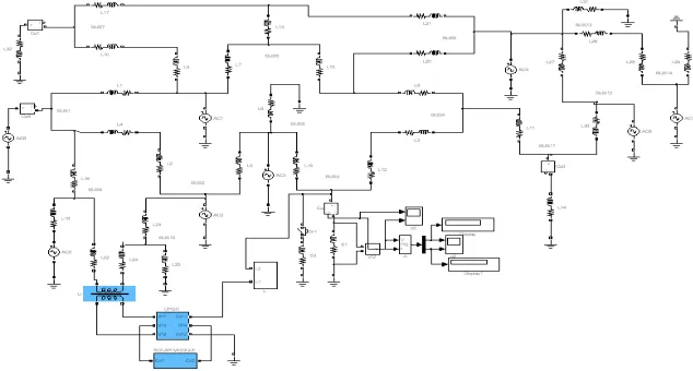
Fig. 2. Circuit Diagram of PV Fed UPQC System
IV. SIMULATION RESULTS
In the proposed system MATLAB software is used for the line compensation. Fig 3 represents the simulation of PV fed UPQC [11] with 14 Bus systems. The corresponding voltage sag, voltage swell, real power and reactive power output is shown. Table 1 represents the comparison of the real and reactive power, with and without compensation at different busses.
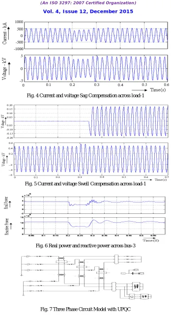
Fig. 4 represents the effective compensation of voltage sag across load 1. At 0.2 second Load 2 (Unbalanced Load) is added which causes voltage sag, at 0.3 second the voltage is compensated across load 1.
Fig. 5 shows the compensation of voltage swell. Here at 0.3 second the voltage swell across load-1occurs due to light load condition and at 0.35 second voltage swell is compensated with the proposed system.
Fig. 6 shows the effective compensation of real and reactive power across bus-3 under voltage sag condition Fig. 7 shows the three phase implementation of the proposed system
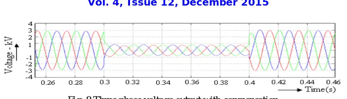
Fig. 8 shows the occurrence of voltage sag at 0.3 second and compensation of the sag at 0.4 second by implementing the proposed technique.
Fig. 4 Current and voltage Sag Compensation across load-1
Fig. 5 Current and voltage Swell Compensation across load-1
Fig. 6 Real power and reactive power across bus-3
Fig. 8 Three phase voltage output with compensation
Table 1. Comparison of Real and Reactive power at Different Buses in 14 bus proposed system
Bus No Real Power ( MW) Without Compensation Real Power ( MW) With Compensation Reactive Power ( MVA) Without Compensation Reactive Power ( MVA) With Compensation BUS-7 0.135 0.136 0.032 0.33
BUS-1 0.267 0.267 0.279 0.28 BUS-3 0.21 0.356 0.693 1.09
BUS-4 0.992 1.12 1.03 1.13
V. CONCLUSIONS
This study describes a combined operation of the unified power quality conditioner with photo voltaic generation system. The proposed system can compensate voltage sag, voltage interruption, harmonic generation and real, reactive power compensation. The VA rating of series and shunt inverters of UPQC are estimated for proposed system. The economic saving due to use of proposed system is estimated nearly 20%. Series converter draws supply from the main source and acts as a controlled rectifier for controlling the terminal voltage and Shunt converter controls the power flow. Thus the both converters control the voltage sag and power flow. The circuit with series converter and shunt inverter section is simulated. The circuit is also simulated with photo volatile system, series and shunt inverter. The performances of both the model are compared. The combined circuit gives better performance in power quality problems. The circuit is implemented using PIC controller. Both simulation and hardware results are verified.
REFERENCES
1. M. Davari, Graduate Student Member, IEEE, and S.M. Ale-Emran, and H. Yazdanpanahi and G. B. Gharehpetian, Senior Member, IEEE “Modeling the Combination of UPQC and Photovoltaic Arrays with Multi-Input Single-Output DC-DC Converter” IEEE Transaction 2011 2. IEEE Std 1159-IEEE Recommended Pradce for monitoring Electnc Power Quality. June 1995
3. Hideaki Fujita and Hirofumi Akagi. “The Unified Power Quality Condotioner: The Integration of series- and shunt-Active Filters” IEEE transaction on power electronics. vol.13. no.2. March 1998
4. H. Matsuo, W. Lin, F. Kurokawa, T. Shigemizu andN. Watanabe. “Characteristics of the Multiple- Input DC-DC Converter.” IEEE Trans on Ind Electronics. Vol.51. no.3. pp.625-631. June 2004
5. Lorenzo. E. “Solar Electricity Engineering of Photovoltaic Systems.” Internationally recognized expert engineers and scientistsof IES (Solar Energy Institute), 1994
6. Altas. I. H: Sharaf.A.M: A PhotovoltaicArray Simulation Model for Matlab-Simulink GUI Environment. Clean Electrical Power. 2007. ICCEP’07. International Conf. 2007. pp.341-345
7. Trishan Esram and Patrick L. Chapman. “Comparison of Photovoltaic Array Maximum Power PointTracking Techniques.” IEEE Transaction of Energy Conversion. vol.22, June2007
8. M. Kesler, “Synchronous reference frame based application design and analysis of unified power quality conditioner,” Ph.D. dissertation, Kocaeli Univ., Kocaeli, Turkey, 2010.
9. V. Khadkikar and A. Chandra, “A new control philosophy for a Unified Power Quality Conditioner (UPQC) to coordinate load-reactive power demand between shunt and series inverters,” IEEE Trans. Power Del.,vol. 23, no. 4, pp. 2522–2534, Oct. 2008
10. Mehdi Forghani Saeed Afsharnia, “Online Wavelet Transform-Based Control Strategy for UPQC Control System”, “Power Delivery, IEEE Transactions. Jan. 2007, vol.22, pp. 481-491
11. R. Noroozian, M. Abedi, G. B. Gharehpetian and S. H. Hosseini, "Ongrid and Off-grid Operation of Multi-Input Single-Output DC-DC Converter based Fuel Cell Generation System", ACEMP’07 and ELECTROMOTION’07 Joint meeting, Sep. 2007 Bodrum Turkey.
13. Cavalcanti, M.C., G.M.S. Azevedo, B.A. Amaral and F.A.S. Neves, 2005. A Photovoltaic generation system with unified power quality conditioner function. 31st Annual conference of IEEE Industrial Electronics society, Nov. 6-10, IEEE, Brazil, pp:750-755.
14. Han, B., B. Bae, H. Kim and S. Baek, 2006. Combined operation of unified power quality conditioner with distributed generation. IEEE Trans. Power Del., 21:330-338.
15. Khadkikar.V, Chandra.A, 2011. A Novel Concept of Simultaneous Voltage sag/swell and Load Reactive Power Compensations Utilizing Seris Inverter of UPQC. Power Electronics, IEEE Transaction. Volume:26, Issue:9.
16. Khadkikar. V, 2012. Enhancing Electric Power Quality Using UPQC: A ComprehensiveOverview. Power Electronics IEEE Transaction on Volume:27,Issue:5
17. Kumar, G.S; Kumar, B.K; Kumar, M.M, 2010. Optimal VA loading of UPQC during mitigation of unbalanced voltage sags with phase jumps in three-phase four wire distribution system, Power System Technology (POWERCON), 2010 International Conference.
BIOGRAPHY
Mr.S.Thulasidharan was born in Tamilnadu, India in 1986. He received his B.Tech(Electrical & Electronics) in Rajiv Gandhi College of Engineering and Technology, Puducherry, Graduating with first class. And Masters in (ME - Power Electronics and Drives) in Mailam Engineering College, Mailam. His research area include Power system Analysis, Renewable Energy, FACTS devices and HVDC transmission system etc.