Aung Zaw Latt (Correspondence)
+This article is published under the terms of the Creative Commons Attribution License 4.0 Author(s) retain the copyright of this article. Publication rights with Alkhaer Publications. Published at: http://www.ijsciences.com/pub/issue/2019-07/
DOI: 10.18483/ijSci.2105; Online ISSN: 2305-3925; Print ISSN: 2410-4477
Transient Stability Analysis of 3-Machine,
7-Bus System Using ETAP
Aung Zaw Latt
1
1
Department of Electrical Power Engineering, Technological University (Maubin), Maubin, Myanmar
Abstract: Nowadays, electrical power systems are advancing through continuing development in interconnection,
practically through the use of new technology and controls. Therefore, the study of power system stability has been known as an important and challenging problem for secure power system operation. Generally, power system stability is classified into steady state, transient and dynamic stability. The analysis of transient stability is one of the important items in the planning and maintaining for security power system operation. The transient stability is defined as the ability of the power system to keep up synchronism when subjected to a severe disturbance. In this paper, the transient stability analysis of 3-machine, 7-bus system has been performed on electrical transient analyzer program (ETAP) and investigated the determination of whether or not synchronism is maintained when occurred a three phase fault on a transmission line. In addition, this paper described the improvement of the transient stability performance by using power system stabilizer (PSS), it was built-in with a specific generator. This PSS is accomplished by exciter control to provide better response to the system modes of oscillations.
Keywords: Transient Stability, Three Phase Fault, PSS, Exciter, ETAP
1. Introduction
The stability of a system defines as the ability of a system to return back to its steady state when system occur a disturbance. Electrical power is generated by synchronous generators that operate in synchronism with the rest of the system or with a bus when both of them have same frequency, phase sequence and voltage. Generally, power system stability is categorized into steady state, transient and dynamic stability. Compare to the steady state, the transient stability have to be given more attention since its influence greatly on the power system. Transient stability studies are needed to ensure that the system can withstand the transient condition following a major disturbance such as sudden application of load or sudden load changing, loss of generation, and fault on the system. Occurrence of disturbances may lead to instability in a system or the machine fall out of synchronism and it will no longer working at synchronous speed. This will lead to power, voltage and current to oscillate drastically. It can cause a reduction of the system components lifetime, expensive operations of the electrical grids and in the worst case, risks of partial system collapses. On the other hand, in the synchronous generator, the damping that the field and damper windings provide to the rotor oscillations is weakened due to excitation control system action. The reason for this is that in the rotor circuits appear additional currents induced by the voltage regulation and those currents oppose
to the currents induced by the rotor speed deviations. Therefore, an additional stabilizing signal was needed and the power system stabilizer (PSS) via excitation control was developed with this intend. In this paper, the transient stability analysis of 3-machine, 7-bus system has been performed on ETAP. ETAP is the most inclusive analysis software for the simulation, design, operation and automation of generation, distribution, and industrial power system. ETAP is developed under an established quality
assurance program and is use worldwide as high impact software. The objective of this paper is to observe the system can withstand the transient condition after the system has been subjected to sever a three phase fault on a transmission line. Furthermore, this paper present the application of PSS accomplished by excitation control can provide transient stability improvement of the system.
2. Study of Transient Stability
Transient Stability Analysis of 3-Machine, 7-Bus System Using ETAP
http://www.ijSciences.com
Volume 8 – July 2019 (07)
48
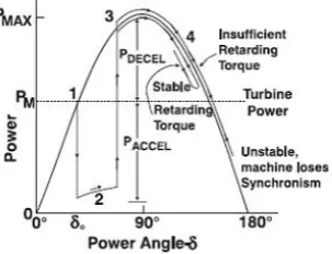
causes the generator rotor to accelerate with respect to the system, increasing the power angle at point 2. When the fault is cleared, the electrical power is restored to a level corresponding to the appropriate point on the power angle curve at point 3. Clearing the fault necessarily eliminates one or more transmission elements from service and at least momentarilyweakens the transmission system. After clearing the fault, the electrical power output of the generator becomes larger than the mechanical power. This causes the unit to decelerate at point 4, reducing the momentum the rotor gained during the fault. If there is enough retarding torque after fault clearing to make up for the acceleration during the fault, the generator will be transient state stable on the first swing and will move back toward its operating point. The power angle will continue to increase until synchronism with the power system is lost if the retarding torque is insufficient.
Fig. 1 Transient stability illustration
2.1 Transient stability enhancement
A number of enhancements can be made to improve the system stability, it depend on the causes of instability problems in a particular system. Typical enhancements include: (a) application of power system stabilizer (PSS), (b) improve configuration and system design, (c) increase synchronizing power, (d ) design and selection of rotating equipment – use induction motors, increase moment of inertia, reduce transient reactance, improve voltage regulator and exciter characteristics, (e) add system protection – fast fault clearance, system separation, etc and (f) add load shedding scheme. In this paper, PSS accomplished by excitation control is applied to provide transient stability improvement of the system.
2.1.1 Power system stabilizer (PSS) and Exciter The PSS installation has been widely used in the power industry to improve the system damping. To provide damping, the PSS must produce a component of electrical torque on the rotor that is in phase with speed variations. The implementation facts vary, depending upon the stabilizer input signal utilized. However, for any input signal, the transfer function of the stabilizer must compensate for the gain and
phase characteristics of the excitation system, the generator, and the power system, which collectively determine the transfer function from the stabilizer output to the component of electrical torque, which can be modulated via excitation control. In this study, IEEE PSS1A simplified version power system stabilizer and IEEE Type 1 exciter are applied to extend stability limits by modulating generator excitation to provide damping to the oscillation of a synchronous machine rotor. Fig. 2 and Fig. 3 show IEEE PSS1A simplified version power system stabilizer and IEEE Type 1 exciter.
1
1 + sT6 KS
sT5
1+ sT5
VSI 1
1+A1s+A2s2
1+ sT1
1+ sT2
1+ sT3
1+ sT4
VSIMAX
VSIMIN
Vs
VST
SI
COMPARATOR RESET TIME DELAY TCR
OPEN SI IF VT < VTMIN
VT
VTMIN
Discontinuous Excitation Controller
Fig. 2 IEEE PSS1A simplified version power system stabilizer
Vt
1 + sTR 1
1 + sTA KA VRmax VRmin -+ Vref +
-KE + sTE 1 SE = f (Efd)
Efd
1 + sTF sKF
Fig. 3 IEEE Type 1 Exciter
2.1.2 Description of generator excitation control system
Transient Stability Analysis of 3-Machine, 7-Bus System Using ETAP
http://www.ijSciences.com
Volume 8 – July 2019 (07)
49
AVR EXCITER GENERATOR
PSS Generator Voltage
Fig. 4 Block diagram of generator excitation control system
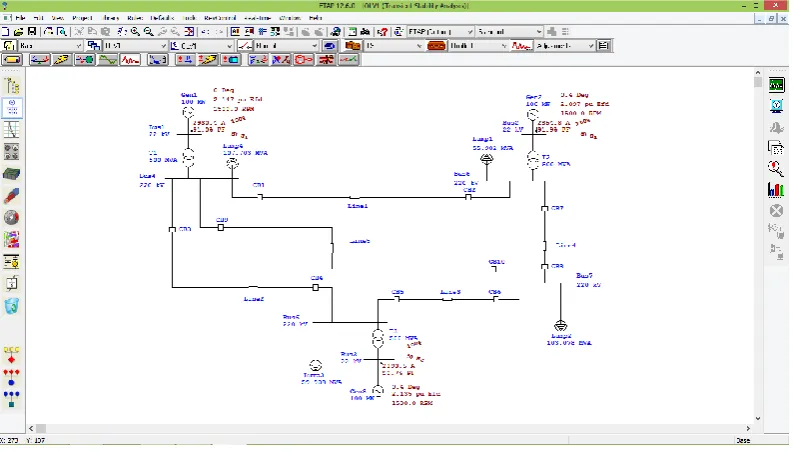
3. System Implementation, Test and Result 3.1 Description of 3-machine, 7-bus test model
Fig. 5 shows simulation test of 3- machine, 7-bus
system model in ETAP. It consists of 7 buses, 3generators, 3 transformers, 4 loads and 5 transmission lines are connected in between the buses. Bus 1 is swing bus, buses 2, 3 are voltage controlled bus and buses 5, 6, 7 are load bus. Although this system model is a relatively small and simple power system network, this system works will assist utility engineers in the planning and maintaining security of power system operation, further aiding students’ learning process. The input parameters of generators, loads, transmission lines, IEEE PSS1A and IEEE Type 1 exciter are given below in the following Table 1 to 7. The comparison results of the system parameters can be seen quickly in simulation plots by using ETAP software.
Fig. 5 Simulation test of 3-machine, 7-bus model in ETAP
TABLE 1: Synchronous generator parameters
Machine Rating Positive Sequence Impedance(%) Zero Seq. Z(%)
ID Model MVA kV Ra Xd’’ Xd’ Xd Xq’’ Xq’ Xq X/R R0 X0
Gen 1 Subtransient, round-rotor 117.647 22 1.00 19.00 28.00 155.00 19.00 65.00 155.00 7.00 1.00 7.00
Gen 2 Subtransient, round-rotor 117.647 22 1.00 19.00 28.00 155.00 19.00 65.00 155.00 7.00 1.00 7.00
Gen 3 Subtransient, round-rotor 117.647 22 1.00 19.00 28.00 155.00 19.00 65.00 155.00 7.00 1.00 7.00
TABLE 2: Synchronous generator’s dynamic parameters
Machine Connected Bus Time Constants (Sec) H(Sec.), D(MWpu/Hz)& Saturation Grounding
ID ID Tdo’’ Tdo’ Tqo’’ Tqo’ H %D S100 S120 Sbreak Conn Type
Gen 1 Bus 1 0.035 6.5 0.035 1.25 39.00 0 1.070 1.18 0.8 Wye Solid
Gen 2 Bus 2 0.035 6.5 0.035 1.25 39.00 0 1.070 1.18 0.8 Wye Solid
Transient Stability Analysis of 3-Machine, 7-Bus System Using ETAP
http://www.ijSciences.com
Volume 8 – July 2019 (07)
50
TABLE 3: Synchronous generator’s mechanical parametersMachine Generator / Motor Coupling Prime Mover/Load Equivalent Total
ID Type RPM WR2 H RPM WR2 H WR2 H RPM WR2 H
Gen 1 Gen. 1500 123904 13 1500 123904 13 123904 13 1500 371712 39
Gen 2 Gen. 1500 123904 13 1500 123904 13 123904 13 1500 371712 39
Gen 3 Gen. 1500 123904 13 1500 123904 13 123904 13 1500 371712 39
TABLE 4: Power System Stabilizer input data (IEEE PSS1A)
Generator ID VSI KS VSTMax VSTMin VTMin TDR A1 A2 T1 T2 T3 T4 T5 T6
Gen 1 Speed 3.15 0.9 -0.9 1500 0.2 0 0 0.76 0.1 0.76 0.1 1 0.1
Gen 2 Speed 3.15 0.9 -0.9 1500 0.2 0 0 0.76 0.1 0.76 0.1 1 0.1
Gen 3 Speed 3.15 0.9 -0.9 1500 0.2 0 0 0.76 0.1 0.76 0.1 1 0.1
TABLE 5: Exciter input data (IEEE Type 1)
Generator ID Control Bus ID KA KE KF TR TA TE TF VRmax VRmin SEmax SE.75 Efdmax
Gen 1 Bus 1 250 1 0.06 0.005 0.03 1.25 1 17.5 -15.5 1.65 1.13 6.6
Gen 2 Bus 2 250 1 0.06 0.005 0.03 1.25 1 17.5 -15.5 1.65 1.13 6.6
Gen 3 Bus 3 250 1 0.06 0.005 0.03 1.25 1 17.5 -15.5 1.65 1.13 6.6
TABLE 6: Transmission line input data
Line ID Length (Adj meter) R1 X1 Y1
Line 1 2000 16.94 108.9 0.0000134
Line 2 2000 12.1 50.82 0.0000093
Line 3
Line 4
Line 5
1000
1000
3000
12.584
13.552
19.36
84
60.5
104.06
0.0000070
0.0000072
0.0000114
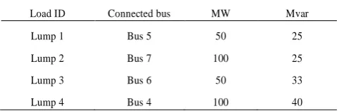
TABLE 7: Load input data
Load ID Connected bus MW Mvar
Lump 1 Bus 5 50 25
Lump 2 Bus 7 100 25
Lump 3
Lump 4
Bus 6
Bus 4
50
100
33
40
3.2 Simulation Test and Result
In this paper, the transient stability performance of 3-machine, 7-bus system is studied by using ETAP software. Firstly, Newton-Raphson method is applied to analyze initial load flow solution. The maximum number of iteration possible is 99, the solution precision for the initial load flow is 0.0001, and the acceleration factor for the initial load flow is 0. The time increment for integration steps (∆t) is 0.001 and the time increment for plots is 20 times ∆t.
Transient Stability Analysis of 3-Machine, 7-Bus System Using ETAP
http://www.ijSciences.com
Volume 8 – July 2019 (07)
51
(a) (b) Fig. 6 Electrical power of generators vs time (a) without, and (b) with PSS1A and Type 1 Exciter
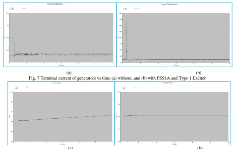
(a) (b) Fig. 7 Terminal current of generators vs time (a) without, and (b) with PSS1A and Type 1 Exciter
(a) (b) Fig. 8 Generator speed vs time (a) without, and (b) with PSS1A and Type 1 Exciter
Transient Stability Analysis of 3-Machine, 7-Bus System Using ETAP
http://www.ijSciences.com
Volume 8 – July 2019 (07)
52
(a) (b) Fig. 10 Bus voltage vs time (a) without, and (b) with PSS1A and Type 1 Exciter
4. Conclusion
In this paper, transient stability analysis of 3-machine, 7-bus system has been carried out on ETAP software. In this study, 3- phase fault is created on transmission line 1 and the fault is cleared by circuit breakers CB1 and CB2 with the help of transient stability study case editor. Power system stabilizer IEEE PSS1A and IEEE Type 1 Exciter are incorporated with a specific generator to enhance the transient stability performance of the system. The simulation has been carried out for generator electrical power, generator terminal current, generator speed, generator relative power angle, bus voltage without, and with PSS1A and Type 1 Exciter. According to Fig (a) of No.6 to 10, it has been observed that the response of the system parameters at initial condition (without application of PSS1A and Type 1 Exciter) are oscillatory due to the effect of 3- phase fault. But, oscillatory nature of the system parameters with the application of PSS1A and Type 1 Exciter are reduced drastically, in addition, the steady state position of the system parameters is reached quickly; it can be seen in Fig (b) of No. 6 to 10. Through these studies, the application of IEEE PSS1A via IEEE Type 1 exciter not only gets better response in terms of oscillatory nature of the system but also quickly brings the steady state position of the system. Therefore, the power system stabilizer uses
auxiliary stabilizing signals to control the excitation system so as to improve power system transient stability performance; this is very effective method of enhancing transient stability performance.
References
1. P. Kundur, “ Power System Stability and Control”, EPRI power system engineering series, McGraw-Hill, New York, 1994.
2. Technical information pointers, “ETAP TIP- No.009. Transient Stability- Events & Actions”, www.eltechs.co.jp, 3. Electrical Transient Analyzer Program (ETAP),
www.etap.com.
4. P.M. Anderson and A. A. Fouad, “Power System Control and Stability”, 2nd
Edition, IEEE press, 2003.
5. ETAP power station user guide, “Chapter 20- User-Defined Dynamic Model”, www.isiacademy-eg.com
6. W. Peter & M. A. Pai, “Power System Dynamics”, Prentice Hall. Inc,1998.
7. P.S.R Murty, “Power System Analysis”, BS Publication, Hyderabad, 2007.
8. Technical documents, “Mitsubishi Electric Power System Stabilizer (PSS)”, https://studylib.net
9. J. Duncan Glover,Thomas J. Overbye, Mulukutla S. Sarma, “ Power System Analysis and Design”, 6th
Edition, Cangage Learning, USA, 2015.
10. Velimir Lackovic, Char. Eng., “Power System Transient Stability Study Fundamentals”, Course No: E03-024, CED Engineering.com
11. D P Kothari, I J Nagrath, “Modern Power System Analysis”, 3rd Edition, Tata McGraw-Hill, New Delhi, 2003.
12. D. Das, “Electrical Power Systems” New Age International