Journal of Today’s Ideas – Tomorrow’s Technologies,
Vol. 3, No. 2, December 2015 pp. 145–160 DOI: 10.15415/jotitt.2015.32010
Implementation of Binary to Gray Code Converters
in Quantum Dot Cellular Automata
SHIFATUL ISLAM, MOHAMMAD ABDULLAH-AL-SHAFI AND ALI NEWAZ BAHAR*
Department of Information & Communication Technology Mawlana Bhashani Science and Technology University, Tangail, Bangladesh.
*Email: [email protected]
Received: August 27, 2015|Revised: September 29, 2015|Accepted: November 2, 2015
Published Online: December 17, 2015
The Author(s) 2015. This article is published with open access at www.chitkara.edu.in/publications
Abstract Quantum dot cellular automaton (QCA) are dominant
nanotechnology which has been used extensively in digital circuits and systems. It is a promising alternative to complementary metal–oxide–semiconductor (CMOS) technology with many enticing features such as high-speed, low power consumption and higher switching frequency than transistor based technology. The code converters are the basic unit for transformation of data to execute arithmetic processes. In this paper, QCA based 2-bit binary-to-gray; 3-bit binary-to-gray and 4-bit binary-to-gray code converter have been proposed. The proposed design reduces the number of cells, area and raises switching speed. The simulations are completed using QCADesigner and
Microwindlite tool which is widely used for simulation and verification.
Keywords: Binary to Gray Converter; Quantum Dot Cellular Automata; Gray
Code; QCA cell.
1. INTRODUCTION
QCA is an advanced access towards the modern era of nanotechnology and an alternative of CMOS technology [1] and offers a new designing procedure which is relevant for logic gates. Physical limits of CMOS such as quantum effects and technological limits like power dissipation; hamper the momentum of microelectronics using regular circuit scaling [2]. QCA is an emerging technology which allows operating frequencies in range of THz [3] that is not achievable in current CMOS technologies.
Islam, Md S. Mohammad, AAS Bahar, AN
In this paper we have designed and implemented a 2-bit binary-to-gray, 3-bit binary-to-gray and 4-bit binary-to-gray code converter in QCA technology. We implement the binary to gray converter in an efficient way using less number of cell and area.
2. FUNDAMENTAL OF QCA
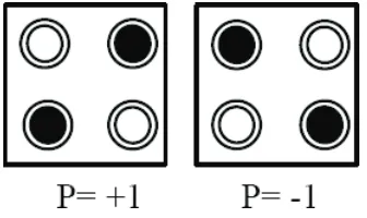
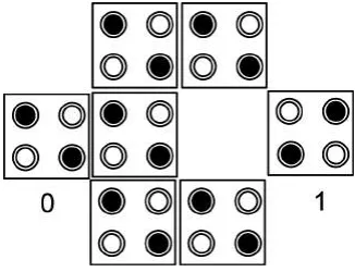
The principal unit of QCA structure is QCA cell and it consists of two electrons with four quantum dots positioned at the vertices of a squared cell [4-6]. Electrons can shift to different quantum dots by means of electron tunneling. The electrons are forced to the corner area to expand their separation due to Coulomb repulsion. The state of a cell is called its polarization. The identical energetically nominal arrangements of the two electrons in the QCA cell, as shown in Figure 1. These two stable arrangements of electrons are denoted as cell polarization P= + 1.00 and P = –1.00. By using cell polarization P =+ 1.00 to represent logic “1” and P = –1.00 to represent logic “0”, binary
data is encoded in the charge composition of the QCA cell [7, 8].
Figure 1: Structure of a basic QCA cell.
A number of QCA combinational [1, 5, 9-22], sequential [23-32] and reversible logic [33-40] circuit have been proposed in recent years based on two cell inverters and three input majority voter elements [10, 17, 41, 42]. Elemental structures for QCA are the inverter and the majority gate. The elemental blocks of QCA logic involve a QCA wire, QCA inverter and QCA majority gate.
2.1 QCA wire
QCA wire is a bundle of interconnecting cells that are used to transfer polarization state. QCA wire can be made up of 45o cells or 90o cells shown
Implementation of Binary to Gray Code Converters in Quantum Dot Cellular Automata
(a)
(b)
Figure 2: QCA (a) 45°wire (b) 90° wire.
2.2. QCA inverter
QCA inverter is generally composed by placing the cells with only their edges contacts. This aspect is employed to forge an inverter as shown in Figure 3. QCA inverter returns the reversed value of the input value.
Figure 3: QCA inverter.
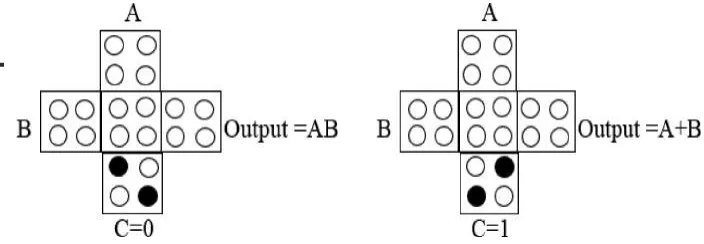
2.3 Majority voter (MV)
Islam, Md S. Mohammad, AAS Bahar, AN
To produce well-organized QCA design, the digital circuits are implemented with the help of majority gate-based design techniques are needed [45]. Logical AND gate and OR gate can be realized from the majority gate as shown in Figure 4.
Figure 4: 2-input AND gate and 2-input OR gate using Majority voter.
3. METHODOLOGY
QCA computation proceeds by direction of cells based on polarization of adjoining cells. An analysis is executed to find out the appropriate tools and verify the proposed circuit. Several approximate simulators as nonlinear approximation processes and bistable simulation engine are used to demonstrate. These procedures do not generate the genuine portion. Then QCA Designer 2.0.3 is preferred and this simulation engine is described [46]. QCA Designer is a tool used for model and simulation of QCA based circuit evolved at the ATIPS Laboratory. The functionality of the circuit is tested by QCA Designer 2.0.3 [47] which encompasses default values such as cell size, number of samples, radius of effect, convergence tolerance, relative permittivity, clock amplitude factor, Relaxation time etc. For implement the code converter in CMOS we used MICROWIND [48] which is a integrated tool for simulation.
4. PROPOSED CIRCUIT AND PRESENTATION
Implementation of Binary to Gray Code Converters in Quantum Dot Cellular Automata
flexibility. It is also efficient in security department for devising and cracking codes.
4.1 Binary code
A code is a symbolic presentation of data and performs text information using the number system. For instance a binary sequence of six bits 110100 is identical to decimal number 52.
4.2 Gray code
Reflected binary code, also known as Gray code is a numeral structure where each value differs only a sole bit from the previous bit. Gray code is not convenient for arithmetic operations. Gray code has many constructive applications including simplify fault correction, terrestrial television, some cable television system, analog-to-digital converter and peripheral apparatus.
5. QCA IMPLEMENTATION OF CODE CONVERTERS
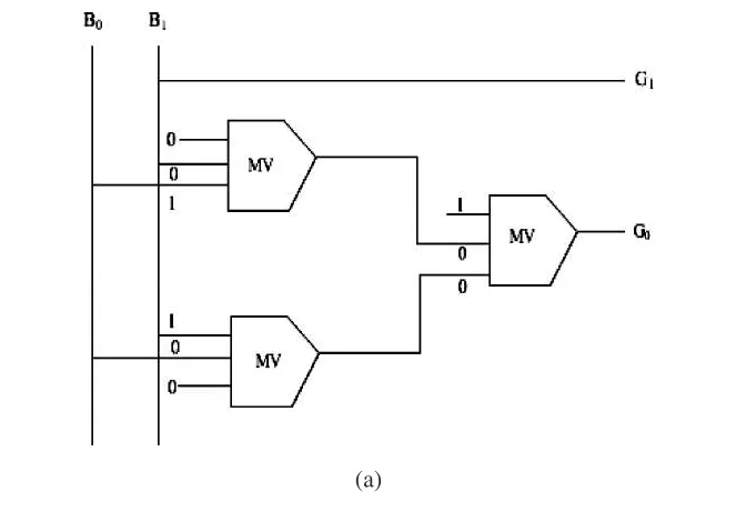
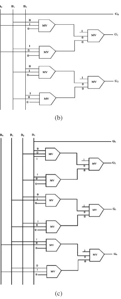
Figure 5 shows the simplified block diagram of 2-bit binary-to-gray, 3-bit binary-to-gray and 4-bit binary-to-gray code converter using majority voter.
Islam, Md S. Mohammad, AAS Bahar, AN
(b)
(c)
Figure 5: Block diagram of (a) 2-bit binary-to-gray (b) 3-bit binary-to-gray
Implementation of Binary to Gray Code Converters in Quantum Dot Cellular Automata
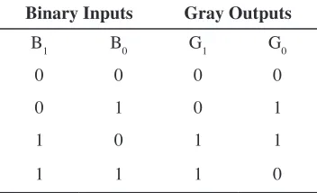
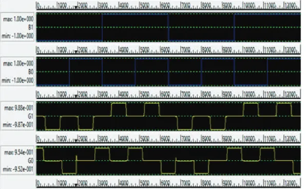
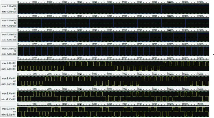
A two bit binary-to-gray code converter composed of two binary inputs B1 and B0 and the corresponding gray outputs are G1 and G0. Three bit binary-to-gray code converter composed of 3-inputs B0, B1 and B2 and the corresponding gray outputs are G0, G1 and G2. Four bit binary-to-gray code converter composed of 4-inputs B3, B2, B1 and B0 and the corresponding gray outputs are G3, G2, G1 and G0.Tables 1 to 3 shows the truth table of binary-to-gray code converter.
Table 1: Truth table Representations of two bit Binary to Gray Code Converter.
Binary Inputs Gray Outputs
B1 B0 G1 G0
0 0 0 0
0 1 0 1
1 0 1 1
1 1 1 0
Table 2: Truth table Representations of three bit Binary to Gray Code Converter.
Binary Inputs Gray Outputs
B0 B1 B2 G0 G1 G2
0 0 0 0 0 0
0 0 1 0 0 1
0 1 0 0 1 1
0 1 1 0 1 0
1 0 0 1 1 0
1 0 1 1 1 1
1 1 0 1 0 1
1 1 1 1 0 0
Table 3: Truth table Representations of four bit Binary to Gray Code Converter.
Binary Inputs Gray Outputs
B3 B2 B1 B0 G3 G2 G1 G0
0 0 0 0 0 0 0 0
0 0 0 1 0 0 0 1
0 0 1 0 0 0 1 1
Islam, Md S. Mohammad, AAS Bahar, AN
0 1 0 0 0 1 1 0
0 1 0 1 0 1 1 1
0 1 1 0 0 1 0 1
0 1 1 1 0 1 0 0
1 0 0 0 1 1 0 0
1 0 0 1 1 1 0 1
1 0 1 0 1 1 1 1
1 0 1 1 1 1 1 0
1 1 0 0 1 0 1 0
1 1 0 1 1 0 1 1
1 1 1 0 1 0 0 1
1 1 1 1 1 0 0 0
6. SIMULATION AND RESULT
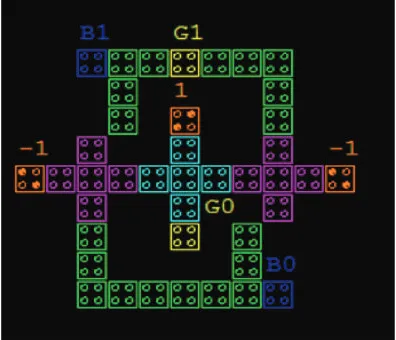
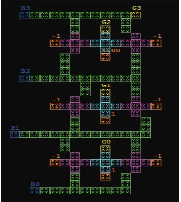
The code converter circuits are designed using QCADesigner 2.0.3. The simulated circuit layout of 2-bit binary to gray, 3-bit binary to gray and 4-bit binary to gray code converter are shown in figure 6 to 8 respectively. The object parameters: cell width × cell height is 18 × 18 and dot diameter is 5.00.
The logical equation of two bit binary to gray code converter is G1 = B1 and G0 = B1⊕B0. For three bit binary to gray code converter the logical equation is G0 = B0, G1 = B1⊕B0 and G2 = B2⊕B1.The logical equation of four bit binary to gray code converter is G3 = B3, G2 = B3⊕B2, G1 = B2⊕B1 and G0 = B1⊕B0.
Implementation of Binary to Gray Code Converters in Quantum Dot Cellular Automata
Figure 7: QCA implementation of three bit binary to gray code converter.
Islam, Md S. Mohammad, AAS Bahar, AN
The functionality of the proposed structure is approved from the simulated waveform. The following parameters are used for Bistable Approximation: Number of samples = 12800, convergence tolerance = 0.001000, radius of effect = 65.000000nm, relative permittivity = 12.900000, clock low = 3.800000e–023J, clock high = 9.800000e–022J, clock shift = 0, clock amplitude factor = 2.000000,
layer separation = 11.500000 and maximum iterations per sample = 100. The above mentioned parameters are mostly default values in QCA Designer. Figure 9 to 11 shows the simulated waveforms of the code converters.
Figure 9: Simulated output of two bit binary to gray code converter.
Implementation of Binary to Gray Code Converters in Quantum Dot Cellular Automata
Figure 11: Simulated output of four bit binary to gray code converter.
For design and simulation the code converter in CMOS we employed MICROWIND. This is a very user-friendly engine to design and find out the covered area of logic gate.
Figure 12: Simulated layout of two bit binary to gray code converter in
Islam, Md S. Mohammad, AAS Bahar, AN
Figure 13: Simulated layout of three bit binary to gray code converter in
CMOS.
Figure 14: Simulated layout offour bit binary to gray code converter in
Implementation of Binary to Gray Code Converters in Quantum Dot Cellular Automata Table 4: Performance Factors of Binary to Gray Code Converter.
Parameter 2 bit B2G 3 bit B2G 4 bit B2G
Total Number of Cells 41 86 131
Number of Clock 3 3 3
Clock delay 0.75 0.75 0.75
Area in QCA (µm2) 0.05 0.12 0.18
Area in CMOS (µm2) 22 44.2 71.78
Improvement (in times) 440 369 399
Figure 15: Comparative Figures for area (size) of QCA and CMOS with
improvement.
CONCLUSION
Islam, Md S. Mohammad, AAS Bahar, AN
REFERENCES
[1] Cho, H. and Swartzlander, E. E., Adder and multiplier design in quantum-dot cellular automata, IEEE Transactions on Computers, 58(6), 2009, 721-727.
http://dx.doi.org/10.1109/TC.2009.21
[2] Lent C.S., Tougaw P.D., Porod W.D., and Bernstein., G.H. Quantum cellular automata, Nanotechnology, 4(1), 1993, 49–57.
[3] Seminario J.M, Derosa P.A, Cordova L.E and Bozard B.H., A molecular device operating at terahertz frequencies, IEEE Transactions on Nanotechnology, 3(1), 2004, 215–218.
http://dx.doi.org/ 10.1109/TNANO.2004.824012
[4] Zhang, R., Walus, K., Wang, W., and Jullien, G. A., A method of majority logic reduction for quantum cellular automata, IEEE Transactions on Nanotechnology, 3(4), 2008, 443-450.
http://dx.doi.org/ 10.1109/TNANO.2004.834177
[5] Hänninen, I. and Takala, J., Binary adders on quantum-dot cellular automata. Journal of Signal Processing Systems, 58(1), 2010, 87-103. http://dx.doi.org/ 10.1007/s11265-008-0284-5 [6] Kummamuru, R. K et al., Operation of a quantum-dot cellular automata (QCA) shift register
and analysis of errors, IEEE Transactions on Electron Devices, 50(9), 2003, 1906-1913.
http://dx.doi.org/ 10.1109/TED.2003.816522
[7] Tougaw, P. D., Lent, C. S., and Porod, W., Bistable saturation in coupled quantum-dot cells, Journal of Applied Physics, 74(5),1993, 3558-3566.
http://dx.doi.org/ 10.1063/1.354535
[8] Lent, C. S., Tougaw, P. D., and Porod, W., Bistable saturation in coupled quantum dots for quantum cellular automata, Applied Physics Letters, 62(7), 1993, 714-716.
http://dx.doi.org/ 10.1063/1.108848
[9] Azghadi MR, Kavehei O, Navi K., A novel design for quantum-dot cellular automata cells and full adders. J Appl Sci 7(22), 2007, 3460–3468.
[10] Cho H and Swartzlander EE., Adder designs and analyses for quantum-dot cellular automata. Nanotechnol IEEE Trans 6(3), 2007, 374–383.
http://dx.doi.org/ 10.1109/TNANO.2007.894839
[11] Gin A, Williams S, Meng H, Tougaw PD., Hierarchical design of quantum-dot cellular automata devices. J Appl Phys 85(7), 1999, 3713–3720.
http://dx.doi.org/10.1063/1.369737
[12] Ke-ming Q and Yin-shui X., Quantum-dots cellular automata comparator. In: 7th International Conference on ASIC. IEEE, Guilin, 22-25, Oct.2007.
http://dx.doi.org/ 10.1109/ICASIC.2007.4415874
[13] Kim K, Wu K, Karri R., The robust qca adder designs using composable qca building blocks. IEEE Trans Comput Aided Des Integrated Circ Syst 26(1), 2007, 176–183.
http://dx.doi.org/ 10.1109/TCAD.2006.883921
[14] Mardiris VA and Karafyllidis IG., Design and simulation of modular 2n to 1 quantum-dot cellular automata (QCA) multiplexers. Int J Circ Theor Appl 38, 2010, 771–785.
http://dx.doi.org/ 10.1002/cta.595
[15] Navi K, Farazkish R, Sayedsalehi S, Azghadi MR., A new quantum-dot cellular automata full-adder. Microelectron J 41(12), 2010, 820–826.
http://dx.doi.org/ 10.1016/j.mejo.2010.07.003
[16] Sara H, Mohammad T, Keivan N., An efficient quantum-dot cellular automata full-adder. Sci
Res Essays 7(2), 2012, 177–189.
[17] Sayedsalehi S, Moaiyeri MH, Navi K., Novel efficient adder circuits for quantum-dot cellular
automata. J Comput Theor Nanosci 8(9), 2011, 1769-1775.
Implementation of Binary to Gray Code Converters in Quantum Dot Cellular Automata
[18] Srivastava S, and Bhanja S., Hierarchical probabilistic macromodeling for qca circuits. IEEE Trans Comput 56(2), 2007, 174–190.
http://dx.doi.org/10.1109/TC.2007.30
[19] Tougaw PD and Lent CS., Logical devices implemented using quantum cellular automata. J Appl Phys 75(3), 1994, 1818–1825.
http://dx.doi.org/10.1063/1.356375
[20] Vetteth A, Walus K, Dimitrov VS, Jullien GA., Quantum-dot cellular automata carry-look-ahead adder and barrel shifter. IEEE Emerging Telecommunications Technologies Conference, 2002, 2-4.
[21] Wang W, Walus K, Jullien GA., Quantum-dot cellular automata adders. In: 2003 Third IEEE Conference on Nanotechnology, NANO’03, 1, 2003, 461-464.
http://dx.doi.org/ 10.1109/NANO.2003.1231818
[22] Zhang R, Walus K, Wang W, Jullien GA., Performance comparison of quantum-dot cellular automata adders. In: IEEE International Symposium on Circuits and Systems, ISCAS 2005, IEEE, 3, 2005, 2522-2526.
http://dx.doi.org/10.1109/ISCAS.2005.1465139
[23] Askari M, Taghizadeh M, Fardad K., Design and analysis of a sequential ring counter for qca implementation. In: International Conference on Computer and Communication Engineering. IEEE, Kuala Lumpur, 13-15 May 2008.
http://dx.doi.org/ 10.1109/ICCCE.2008.4580743
[24] Dehkordi MA, Shamsabadi AS, Ghahfarokhi BS, Vafaei A., Novel ram cell designs based on inherent capabilities of quantum-dot cellular automata. Microelectron J 42(5), 2011, 701–708.
http://dx.doi.org/10.1016/j.mejo.2011.02.006
[25] Ghosh B, Gupta S, Kumari S, Salimath A., Novel design of combinational and sequential logical structures in quantum dot cellular automata. J Nanostructure Chem 3(1), 2013, 1–9.
http://dx.doi.org/10.1186/2193-8865-3-15
[26] Huang J, Momenzadeh M, Lombardi F., Design of sequential circuits by quantum-dot cellular automata. Microelectron J 38(4), 2007, 525–537.
http://dx.doi.org/10.1016/j.mejo.2007.03.013
[27] Sen B, Goswami M, Some S, Sikdar BK., Design of sequential circuits in multilayer qca structure. In: International Symposium on Electronic System Design (ISED). IEEE, Singapore, 10-12 December 2013.
http://dx.doi.org/10.1109/ISED.2013.11
[28] Vankamamidi V, Ottavi M, Lombardi F., A serial memory by quantum-dot cellular automata (qca). IEEE Trans Comput 57(5), 2008, 606–618.
http://dx.doi.org/10.1109/TC.2007.70831
[29] Venkataramani P, Srivastava S, and Bhanja S., Sequential circuit design in quantum-dot cellular automata. Nanotechnology, 2008. NANO’08. 8th IEEE Conference on, IEEE, 2008, 534-537.
http://dx.doi.org/10.1109/NANO.2008.159
[30] Wu CB, Xie GJ, Xiang YL, Lv HJ., Design and simulation of dual-edge triggered sequential circuits in quantum-dot cellular automata. J Comput Theor Nanosci 11(7), 2014, 1620–1626.
http://dx.doi.org/10.1166/jctn.2014.3541
[31] Xiao LR, Chen XX, Ying SY., Design of dual-edge triggered flip-flops based on quantum-dot
cellular automata. J Zhejiang University Sci C 13(5), 2012, 385-392.
http://dx.doi.org/ 10.1631/jzus.C1100287
[32] Yang X, Cai L, Zhao X, Zhang N., Design and simulation of sequential circuits in
quantum-dot cellular automata: falling edge-triggered flip-flop and counter study. Microelectron J 41(1),
2010, 56–63.
Islam, Md S. Mohammad, AAS Bahar, AN
[33] Bahar, A.N., Waheed, S., Uddin, M, A., and Habib, M.A., Double Feynman Gate (F2G) in Quantum-dot Cellular Automata (QCA), International Journal of Computer Science Engineering (IJCSE), 02(6), 2013, 351-355.
[34] Bahar, A.N., Habib, M.A., and Biswas, N.K., A Novel Presentation of Toffoli Gate in Quantum-dot Cellular Automata (QCA), International Journal of Computer Applications (IJCA), 82(10), 2013, 1-4.
[35] Bahar, A.N., Waheed, S., and Habib, M.A., A novel presentation of reversible logic gate in Quantum-dot Cellular Automata (QCA), 1st International Conference on Electrical Engineering and Information Communication Technology (ICEEICT), IEEE, 2014, 1-6.
http://dx.doi.org/ 10.1109/ICEEICT.2014.6919121
[36] Sarker, A., Bahar, A.N., Biswas, P.K., and Morshed, M., A Novel Presentation of Peres Gate
(PG) in Quantum-Dot Cellular Automata (QCA), European Scientific Journal, 10(21), 2014.
[37] Islam, S.S., Farzana, S., and Bahar, A.N., Area efficient layout design of Multiply Complements
Logic (MCL) gate using QCA Technology, Global Journal of Researches in Engineering-J General Engineering, North America, 14(4), 2014, 7-10.
[38] Bahar, A.N., Waheed, S., and Hossain, N., A new approach of presenting reversible logic gate in nanoscale, Springer Plus, 4:153, 2015.
http://dx.doi.org/10.1186/s40064-015-0928-4
[39] Bahar, A.N., Waheed, S., and Habib, M.A., An Efficient Layout Design of Fredkin Gate in
Quantum-dot Cellular Automata (QCA), Düzce University Journal of Science & Technology, 3(1), 2015, 219-225.
[40] Shafi, M.A., Islam, M.S., and Bahar, A.N., A Review on Reversible Logic Gates and it’s QCA
Implementation, International Journal of Computer Applications (IJCA), 128(2),2015, 27-34.
http://dx.doi.org/10.5120/ijca2015906434
[41] Navi, K., Sayedsalehi, S., Farazkish, R., and Azghadi, M.R., Five-input majority gate, a new device for quantum-dot cellular automata, Journal of Computational and Thoretical Nanoscience, 7, 2010, 1546-1553.
http://dx.doi.org/10.1166/jctn.2010.1517
[42] Rumi, Z., Walus, K., Wei, W., and Jullien, G. A., Performance comparison of quantum-dot cellular automata adders, in Circuits and Systems, ISCAS 2005. IEEE International Symposium on, 2005, 2522-2526.
http://dx.doi.org/10.1109/ISCAS.2005.1465139
[43] Lent, C. S., and Tougaw, P. D., Lines of interacting quantum-dot cells: A binary wire, Journal of Applied Physics, 74(10), 1993, 6227-6233.
http://dx.doi.org/10.1063/1.355196
[44] Imre, A. et al., Majority logic gate for magnetic quantum-dot cellular automata, Science,
311(5758), 2006, 205-208.
http://dx.doi.org/10.1126/science.1120506
[45] Ganesh, E. N., Kishore, L., and Rangachar, M.J.S., Implementation of Quantum cellular automata combinational and sequential circuits using Majority logic reduction method, International Journal of Nanotechnology and Applications, 2(1), 2008.
[46] Walus, K., Dysart, T. J., Jullien, G. A., and Budiman, R. A., QCADesigner: A rapid design and simulation tool for quantum-dot cellular automata. Transactions on Nanotechnology, IEEE, 3(1), 2004, 26-31.
http://dx.doi.org/10.1109/TNANO.2003.820815