C
H
A
P
T
E
R
Kinematics in
Two Dimensions; Vectors
49
CONTENTS
3–1 Vectors and Scalars 3–2 Addition of Vectors—
Graphical Methods 3–3 Subtraction of Vectors, and
Multiplication of a Vector by a Scalar
3–4 Adding Vectors by Components 3–5 Projectile Motion 3–6 Solving Projectile Motion
Problems
3–7 Projectile Motion Is Parabolic 3–8 Relative Velocity
3
This snowboarder flying through the air shows an example of motion in two dimensions. In the absence of air resistance, the path would be a perfect parabola. The gold arrow represents the downward acceleration of gravity, Galileo analyzed the motion of objects in 2 dimensions under the action of gravity near the Earth’s surface (now called “projectile motion”) into its horizontal and vertical components.We will discuss vectors and how to add them. Besides analyzing projectile motion, we will also see how to work with relative velocity.
gB.
49
(b) (a)
A B
(c) (d) (e)
I
n Chapter 2 we dealt with motion along a straight line. We now consider the motion of objects that move in paths in two (or three) dimensions. In par-ticular, we discuss an important type of motion known as projectile motion: objects projected outward near the Earth’s surface, such as struck baseballs and golf balls, kicked footballs, and other projectiles. Before beginning our discussion of motion in two dimensions, we will need a new tool, vectors, and how to add them.g
BCHAPTER-OPENING QUESTION—Guess now!
[Don’t worry about getting the right answer now—youwill get another chance later in the Chapter. See also p. 1 of Chapter 1 for more explanation.]
A small heavy box of emergency supplies is dropped from a moving helicopter at point A as it flies at constant speed in a horizontal direction. Which path in the drawing below best describes the path of the box (neglecting air resistance) as seen by a person standing on the ground?
3–1
Vectors and Scalars
We mentioned in Chapter 2 that the term velocityrefers not only to how fast an object is moving but also to its direction. A quantity such as velocity, which has
directionas well as magnitude, is a vectorquantity. Other quantities that are also vectors are displacement, force, and momentum. However, many quantities have no direction associated with them, such as mass, time, and temperature. They are speci-fied completely by a number and units. Such quantities are called scalarquantities. Drawing a diagram of a particular physical situation is always helpful in physics, and this is especially true when dealing with vectors. On a diagram, each vector is represented by an arrow. The arrow is always drawn so that it points in the direction of the vector quantity it represents. The length of the arrow is drawn proportional to the magnitude of the vector quantity. For example, in Fig. 3–1, green arrows have been drawn representing the velocity of a car at various places as it rounds a curve. The magnitude of the velocity at each point can be read off Fig. 3–1 by measuring the length of the corresponding arrow and using the scale shown
When we write the symbol for a vector, we will always use boldface type, with a tiny arrow over the symbol. Thus for velocity we write If we are concerned only with the magnitude of the vector, we will write simply v, in italics, as we do for other symbols.
3–2
Addition of Vectors—Graphical
Methods
Because vectors are quantities that have direction as well as magnitude, they must be added in a special way. In this Chapter, we will deal mainly with displacement vectors, for which we now use the symbol and velocity vectors, But the results will apply for other vectors we encounter later.
We use simple arithmetic for adding scalars. Simple arithmetic can also be used for adding vectors if they are in the same direction. For example, if a person walks 8 km east one day, and 6 km east the next day, the person will be
east of the point of origin. We say that the netorresultant
displacement is 14 km to the east (Fig. 3–2a). If, on the other hand, the person walks 8 km east on the first day, and 6 km west (in the reverse direction) on the second day, then the person will end up 2 km from the origin (Fig. 3–2b), so the resultant displacement is 2 km to the east. In this case, the resultant displacement is obtained by subtraction:
But simple arithmetic cannot be used if the two vectors are not along the same line. For example, suppose a person walks 10.0 km east and then walks 5.0 km north. These displacements can be represented on a graph in which the positive
yaxis points north and the positive xaxis points east, Fig. 3–3. On this graph, we draw an arrow, labeled to represent the 10.0-km displacement to the east. Then we draw a second arrow, to represent the 5.0-km displacement to the north. Both vectors are drawn to scale, as in Fig. 3–3.
DB2, DB1,
8km - 6km = 2km. 8km + 6km = 14km
vB.
DB,
vB.
(1cm = 90km兾h). Scale for velocity:
1 cm = 90 km/h
FIGURE 3;1 Car traveling on a road, slowing down to round the curve. The green arrows represent the velocity vector at each position.
Resultant = 14 km (east)
Resultant = 2 km (east) 6 km
8 km
8 km
6 km
x(km) East
x(km) East
(a)
(b)
0
0
FIGURE 3;2 Combining vectors in one dimension.
0
2
1
South
Resultant displacement
West θ
2 2 4 6
4 6 8 10
DB DB
y(km)
North
x(km) East
R
= 1+ 2
D
B
D
B
D
B FIGURE 3;3 A person walks 10.0 km east and then 5.0 km
north. These two displacements are represented by the vectors and which are shown as arrows. Also shown is the resultant displacement vector, which is the vector sum of and Measurement on the graph with ruler and protractor shows that has a magnitude of 11.2 km and points at an angle u = 27° north of east.
DBR DB2.
DB1
DBR, DB2,
After taking this walk, the person is now 10.0 km east and 5.0 km north of the point of origin. The resultant displacementis represented by the arrow labeled in Fig. 3–3. (The subscript R stands for resultant.) Using a ruler and a protractor, you can measure on this diagram that the person is 11.2 km from the origin at an angle north of east. In other words, the resultant displacement vector has a magnitude of 11.2 km and makes an angle with the positive xaxis. The magnitude (length) of can also be obtained using the theorem of Pythagoras in this case, because and form a right triangle with as the hypotenuse. Thus
You can use the Pythagorean theorem only when the vectors are perpendicular
to each other.
The resultant displacement vector, is the sum of the vectors and That is,
This is a vectorequation. An important feature of adding two vectors that are not along the same line is that the magnitude of the resultant vector is not equal to the sum of the magnitudes of the two separate vectors, but is smaller than their sum. That is,
where the equals sign applies only if the two vectors point in the same direction.
In our example (Fig. 3–3), whereas equals 15 km,
which is the total distance traveled. Note also that we cannot set equal to 11.2 km, because we have a vector equation and 11.2 km is only a part of the resultant vector, its magnitude. We could write something like this, though:
Figure 3–3 illustrates the general rules for graphically adding two vectors together, no matter what angles they make, to get their sum. The rules are as follows:
1. On a diagram, draw one of the vectors—call it —to scale.
2. Next draw the second vector, to scale, placing its tail at the tip of the first vector and being sure its direction is correct.
3. The arrow drawn from the tail of the first vector to the tip of the second vector represents the sum, or resultant, of the two vectors.
The length of the resultant vector represents its magnitude. Note that vectors can be moved parallel to themselves on paper (maintaining the same length and angle) to accomplish these manipulations. The length of the resultant can be measured with a ruler and compared to the scale. Angles can be measured with a protractor. This method is known as the tail-to-tip method of adding vectors.
The resultant is not affected by the order in which the vectors are added. For example, a displacement of 5.0 km north, to which is added a displacement of 10.0 km east, yields a resultant of 11.2 km and angle (see Fig. 3–4), the same as when they were added in reverse order (Fig. 3–3). That is, now using to represent any type of vector,
[Mathematicians call this equation the commutativeproperty of vector addition.]
VB1 + V B
2 = V
B 2 + V
B 1. VB
u = 27°
DB2,
DB1 DBR = DB1 + D
B
2 = (11.2km, 27° N of E).
DBR D1 + D2 DR = 11.2km,
DR AD1 + D2B, DBR = DB1 + D
B 2.
DB2. DB1
DBR,
= 3125km2 = 11.2km.
DR = 3D12 + D22 = 3(10.0km)2 + (5.0km)2
DR DR
D1, D2,
DBR
u = 27°
u = 27°
DBR
SECTION 3–2 Addition of Vectors—Graphical Methods
51
0 West
South
1
R
= 2+ 1
θ
2 2 4 6
4 6 8 10
2
x(km) East North
y(km)
DB D
B
D
B
D
B DB
The tail-to-tip method of adding vectors can be extended to three or more vectors. The resultant is drawn from the tail of the first vector to the tip of the last one added. An example is shown in Fig. 3–5; the three vectors could represent displacements (northeast, south, west) or perhaps three forces. Check for yourself that you get the same resultant no matter in which order you add the three vectors.
+
+
=
1
1
R
2 2
3
3
VB VB
VB
VB
VB VB
VB FIGURE 3;5 The resultant of three
vectors:VBR = V
B
1 + V
B
2 + V
B
3.
C A U T I O N
Be sure to use the correct diagonal on the parallelogram to get the resultant
INCO RRECT
(a)
(b)
(c)
Tail-to-tip
Parallelogram
Wrong
+
=
=
=
11
1
1 2
2
2
2 R
VB V
B V
B
VB
VB
VB
R
VB
VB
VB
VB FIGURE 3;6 Vector addition by two
different methods, (a) and (b). Part (c) is incorrect.
It is a common error to draw the sum vector as the diagonal running between the tips of the two vectors, as in Fig. 3–6c.This is incorrect: it does not represent the sum of the two vectors. (In fact, it represents their difference, as we will see in the next Section.)
Range of vector lengths. Suppose two vectors each have length 3.0 units. What is the range of possible lengths for the vector representing the sum of the two?
RESPONSE The sum can take on any value from where the vectors point in the same direction, to when the vectors are antiparallel. Magnitudes between 0 and 6.0 occur when the two vectors are at an angle other than 0° and 180°.
EXERCISE A If the two vectors of Example 3–1 are perpendicular to each other, what is the resultant vector length?
3–3
Subtraction of Vectors, and
Multiplication of a Vector by a Scalar
Given a vector we define the negativeof this vector to be a vector with the same magnitude as but opposite in direction, Fig. 3–7. Note, however, that no vector is ever negative in the sense of its magnitude: the magnitude of every vector is positive. Rather, a minus sign tells us about its direction.
VB
A–VBB VB,
0 (= 3.0 - 3.0)
6.0 (= 3.0 + 3.0)
CONCEPTUAL EXAMPLE 3;1
VB2 - V B 1,
–VB VB
A second way to add two vectors is the parallelogram method. It is fully equiva-lent to the tail-to-tip method. In this method, the two vectors are drawn starting from a common origin, and a parallelogram is constructed using these two vectors as adjacent sides as shown in Fig. 3–6b. The resultant is the diagonal drawn from the common origin. In Fig. 3–6a, the tail-to-tip method is shown, and we can see that both methods yield the same result.
We can now define the subtraction of one vector from another: the difference between two vectors is defined as
That is, the difference between two vectors is equal to the sum of the first plus the negative of the second. Thus our rules for addition of vectors can be applied as shown in Fig. 3–8 using the tail-to-tip method.
VB2 - V B
1 = V
B
2 + A–V B
1B. VB2 - V
B 1
SECTION 3–4 Adding Vectors by Components
53
–
=
+
– 1=
– 1
1
2
– 1
2 2
2
VB VB VB VB
VB VB VB
VB
FIGURE 3;8 Subtracting two vectors:VB2 - V
B
1.
FIGURE 3;10 Resolving a vector into its components along a chosen set of xandyaxes. The components, once found, themselves represent the vector. That is, the components contain as much information as the vector itself.
VB = 1.5
2
= −2.0
3 VB
VB VB
VB VB FIGURE 3;9 Multiplying a vector by a scalar cgives a vector whose magnitude is ctimes greater and in the same direction as (or opposite direction if cis negative).
VB
VB
θ
C
North
East
North
East
y
x
B A
(a)
y
x
(b)
0 0
(= 30°) (= 30°)
θ
x y
VB
VB
VB
VB
A vector can be multiplied by a scalar c. We define their product so that has the same direction as and has magnitude cV. That is, multiplication of a vector by a positive scalar cchanges the magnitude of the vector by a factor cbut doesn’t alter the direction. If cis a negative scalar (such as ), the magnitude of the product is changed by the factor (where means the magnitude of c), but the direction is precisely opposite to that of VB. See Fig. 3–9.
∑c∑ ∑c∑
cVB
–2.0
VB
cVB VB
EXERCISE B What does the “incorrect” vector in Fig. 3–6c represent? (a) (b)VB1 - V (c) something else (specify).
B
2;
VB2 - V
B
1;
3–4
Adding Vectors by Components
Adding vectors graphically using a ruler and protractor is often not sufficiently accurate and is not useful for vectors in three dimensions. We discuss now a more powerful and precise method for adding vectors. But do not forget graphical methods—they are useful for visualizing, for checking your math, and thus for getting the correct result.
Components
Consider first a vector that lies in a particular plane. It can be expressed as the sum of two other vectors, called the componentsof the original vector. The components are usually chosen to be along two perpendicular directions, such as thexandyaxes. The process of finding the components is known as resolving the vector into its components. An example is shown in Fig. 3–10; the vector could be a displacement vector that points at an angle north of east, where we have chosen the positive xaxis to be to the east and the positive yaxis north. This vector is resolved into its xand ycomponents by drawing dashed lines (AB and AC) out from the tip (A) of the vector, making them perpendicular to thexand yaxes. Then the lines 0B and 0C represent the xand ycomponents of respectively, as shown in Fig. 3–10b. These vector componentsare written
and In this book we usually show vector components as arrows, like vectors, but dashed. The scalar components, and are the magnitudes of the vector components, with units, accompanied by a positive or negative sign depending on whether they point along the positive or negative xor yaxis. As can be seen in Fig. 3–10, by the parallelogram method of adding vectors.
Space is made up of three dimensions, and sometimes it is necessary to resolve a vector into components along three mutually perpendicular directions. In rectangular coordinates the components are VBx, VBy, and VBz.
VBx + VBy = VB
Vy, Vx
VBy. VBx
VB,
VB
u = 30°
Vy V
sin =
Vx V
cos =
Vy Vx
tan =
V2=V2+V2
θ
θ
θ
θ 90°
y x
x y
0
x
y VB
VB
VB
FIGURE 3;12 Finding the components of a vector using trigonometric functions. The equations are valid only if is the angle makes with the positive
xaxis. VB
u
To add vectors using the method of components, we need to use the trigo-nometric functions sine, cosine, and tangent, which we now review.
Given any angle as in Fig. 3–11a, a right triangle can be constructed by drawing a line perpendicular to one of its sides, as in Fig. 3–11b. The longest side of a right triangle, opposite the right angle, is called the hypotenuse, which we label h. The side opposite the angle is labeled o, and the side adjacent is labeleda. We let h, o, and arepresent the lengths of these sides, respectively.
u u,
θ θ θ
(c)
o
a
h h o
a h'
a'
(a) (b)
o'
FIGURE 3;11 Starting with an angle as in (a), we can construct right triangles of different sizes, (b) and (c), but the ratio of the lengths of the sides does not depend on the size of the triangle.
u
We now define the three trigonometric functions, sine, cosine, and tangent (abbre-viated sin, cos, tan), in terms of the right triangle, as follows:
(3;1)
If we make the triangle bigger, but keep the same angles, then the ratio of the length of one side to the other, or of one side to the hypotenuse, remains the same.
That is, in Fig. 3–11c we have: and
Thus the values of sine, cosine, and tangent do not depend on how big the trian-gle is. They depend only on the size of the antrian-gle. The values of sine, cosine, and tangent for different angles can be found using a scientific calculator, or from the Table in Appendix A.
A useful trigonometric identity is
(3;2)
which follows from the Pythagorean theorem ( in Fig. 3–11). That is:
(See Appendix A and inside the rear cover for other details on trigonometric functions and identities.)
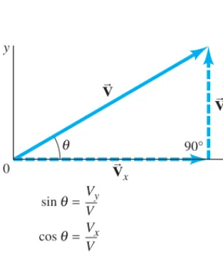
The use of trigonometric functions for finding the components of a vector is illustrated in Fig. 3–12, where a vector and its two components are thought of as making up a right triangle. We then see that the sine, cosine, and tangent are as given in Fig. 3–12, where is the angle makes with the axis. If we multiply the definition of by Von both sides, we get
(3;3a)
Similarly, from the definition of we obtain
(3;3b)
Note that if is not the angle the vector makes with the positive xaxis, Eqs. 3–3 are not valid.
u
Vx = Vcosu.
cosu,
Vy = Vsinu.
sinu = Vy兾V
±x VB
u
sin2u + cos2u = o 2
h2 + a2 h2 =
o2 + a2 h2 =
h2 h2 = 1. o2 + a2 = h2
sin2u + cos2u = 1
o兾a = o¿兾a¿.
o兾h = o¿兾h¿;
a兾h = a¿兾h¿; tanu = side opposite
side adjacent =
o a.
cosu = side adjacent hypotenuse =
a h
sinu = side opposite hypotenuse =
Using Eqs. 3–3, we can calculate and for any vector, such as that illus-trated in Fig. 3–10 or Fig. 3–12. Suppose represents a displacement of 500 m in a direction 30° north of east, as shown in Fig. 3–13. Then From a
calculator or Tables, and Then
There are two ways to specify a vector in a given coordinate system:
1. We can give its components, and
2. We can give its magnitude Vand the angle it makes with the positive xaxis.
We can shift from one description to the other using Eqs. 3–3, and, for the reverse, by using the theorem of Pythagoras†and the definition of tangent:
(3;4a)
(3;4b)
as can be seen in Fig. 3–12.
Adding Vectors
We can now discuss how to add vectors using components. The first step is to resolve each vector into its components. Next we can see, using Fig. 3–14, that the addition of any two vectors and to give a resultant, implies that
(3;5)
That is, the sum of the xcomponents equals the xcomponent of the resultant vector, and the sum of the ycomponents equals the ycomponent of the resultant, as can be verified by a careful examination of Fig. 3–14. Note that we do notaddx compo-nents to ycomponents.
If the magnitude and direction of the resultant vector are desired, they can be obtained using Eqs. 3–4.
VRy = V1y + V2y. VRx = V1x + V2x
VBR = VB1 + V B 2, VB2
VB1
tanu = Vy
Vx
V = 3Vx2 + Vy2
u Vy. Vx
Vy = V sinu = (500m)(0.500) = 250m(north). Vx = Vcosu = (500m)(0.866) = 433m(east),
cos 30° = 0.866. sin 30° = 0.500
V = 500m.
VB Vy Vx
SECTION 3–4
55
Vy=Vsinθ= 250 m
Vx=Vcosθ= 433 m
V = V2+V2 y
x = 500 m North
East
(a)
y
x
(b)
0
θ= 30° North
East
y
x
0
θ= 30°
(V= 500 m)
x y
VB VB VB
VB
FIGURE 3;13 (a) Vector
represents a displacement of 500 m at a 30° angle north of east. (b) The components of are and whose magnitudes are given on the right in the diagram.
VBy, VBx VB
VB
†In three dimensions, the theorem of Pythagoras becomes where is the
component along the third, or z, axis.
Vz V= 3Vx2 +Vy2+ Vz2,
y
x
VRx
VRy
V1x
V2x
V1y
V2y
0
1
= 1+ 2
2
VR
B V
B V
B
VB
VB FIGURE 3;14 The components of are
and VRy = V1y + V2y.
VRx = V1x + V2x VBR = V
B
1 + V
B
The components of a given vector depend on the choice of coordinate axes. You can often reduce the work involved in adding vectors by a good choice of axes—for example, by choosing one of the axes to be in the same direction as one of the vectors. Then that vector will have only one nonzero component.
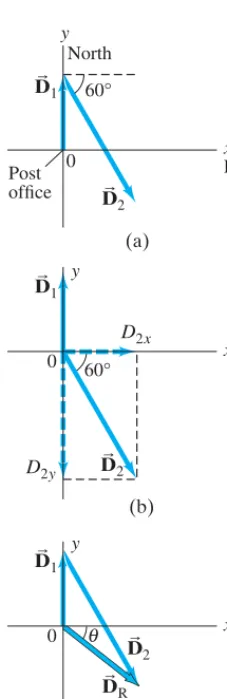
Mail carrier’s displacement. A rural mail carrier leaves the post office and drives 22.0 km in a northerly direction. She then drives in a direc-tion 60.0° south of east for 47.0 km (Fig. 3–15a). What is her displacement from the post office?
APPROACH We choose the positive xaxis to be east and the positive yaxis to be north, since those are the compass directions used on most maps. The origin of the xycoordinate system is at the post office. We resolve each vector into its
xandycomponents. We add the xcomponents together, and then the y compo-nents together, giving us the xandycomponents of the resultant.
SOLUTION Resolve each displacement vector into its components, as shown in Fig. 3–15b. Since has magnitude 22.0 km and points north, it has only a
ycomponent:
has both xandycomponents:
Notice that is negative because this vector component points along the negativeyaxis. The resultant vector, has components:
This specifies the resultant vector completely:
We can also specify the resultant vector by giving its magnitude and angle using Eqs. 3–4:
A calculator with a key labeled INV TAN, or ARC TAN, or gives The negative sign means below the
xaxis, Fig. 3–15c. So, the resultant displacement is 30.0 km directed at 38.5° in a southeasterly direction.
NOTE Always be attentive about the quadrant in which the resultant vector lies. An electronic calculator does not fully give this information, but a good diagram does.
As we saw in Example 3–2, any component that points along the negative xor
yaxis gets a minus sign. The signs of trigonometric functions depend on which “quadrant” the angle falls in: for example, the tangent is positive in the first and third quadrants (from 0° to 90°, and 180° to 270°), but negative in the second and fourth quadrants; see Appendix A, Fig. A–7. The best way to keep track of angles, and to check any vector result, is always to draw a vector diagram, like Fig. 3–15. A vector diagram gives you something tangible to look at when analyzing a problem, and provides a check on the results.
The following Problem Solving Strategy should not be considered a prescrip-tion. Rather it is a summary of things to do to get you thinking and involved in the problem at hand.
u = 38.5° tan–1(–0.796) = –38.5°.
u = tan
–1
tanu = DRy
DRx =
–18.7km
23.5km = –0.796.
DR = 3DR2x + DR2y = 3(23.5km)2 + (–18.7km)2 = 30.0km DRx = 23.5km,
DRy = –18.7km.
DRy = D1y + D2y = 22.0km + (–40.7km) = –18.7km. DRx = D1x + D2x = 0km + 23.5km = ±23.5km
DBR,
D2y
D2y = –(47.0km)(sin 60°) = –(47.0km)(0.866) = –40.7km.
D2x = ±(47.0km)(cos 60°) = ±(47.0km)(0.500) = ±23.5km
DB2
D1x = 0,
D1y = 22.0km.
DB1 EXAMPLE 3;2
P R O B L E M S O L V I N G
Identify the correct quadrant by drawing a careful diagram y
x
East
(a)
y
x
(b) 0
0 0
D2x
y
x
(c)
D2y
Post office
North
60°
θ 60° 1
2
2
2 1
1 DB
DB
DB
DB
DB
DBR DB
FIGURE 3;15 Example 3–2. (a) The two displacement vectors,
and (b) is resolved into its components. (c) and are added to obtain the resultant The component method of adding the vectors is explained in the Example.
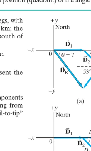
Three short trips. An airplane trip involves three legs, with two stopovers, as shown in Fig. 3–16a. The first leg is due east for 620 km; the second leg is southeast (45°) for 440 km; and the third leg is at 53° south of west, for 550 km, as shown. What is the plane’s total displacement?
APPROACH We follow the steps in the Problem Solving Strategy above.
SOLUTION
1. Draw a diagram such as Fig. 3–16a, where and represent the three legs of the trip, and is the plane’s total displacement.
2. Choose axes: Axes are also shown in Fig. 3–16a:xis east,ynorth.
3. Resolve components: It is imperative to draw a good diagram. The components are drawn in Fig. 3–16b. Instead of drawing all the vectors starting from a common origin, as we did in Fig. 3–15b, here we draw them “tail-to-tip” style, which is just as valid and may make it easier to see.
4. Calculate the components:
We have given a minus sign to each component that in Fig. 3–16b points in the or direction. The components are shown in the Table in the margin.
5. Add the components: We add the xcomponents together, and we add the
ycomponents together to obtain the xand ycomponents of the resultant:
The xandycomponents of the resultant are 600 km and and point respectively to the east and south. This is one way to give the answer.
6. Magnitude and direction: We can also give the answer as
Thus, the total displacement has magnitude 960 km and points 51° below the
xaxis (south of east), as was shown in our original sketch, Fig. 3–16a. so u = –51°. tanu = DRy
DRx =
–750km
600km = –1.25,
DR = 3DR2x + DR2y = 3(600)2 + (–750)2km = 960km –750km,
DRy = D1y + D2y + D3y = 0km - 311km - 439km = –750km. DRx = D1x + D2x + D3x = 620km + 311km - 331km = 600km
–y –x
D3y = –D3sin 53° = –(550km)(0.799) = –439km. DB3:D3x = –D3cos 53° = –(550km)(0.602) = –331km
D2y = –D2sin 45° = –(440km)(0.707) = –311km DB2:D2x = ±D2cos 45° = ±(440km)(0.707) = ±311km
D1y = ±D1sin 0° = 0km DB1:D1x = ±D1cos 0° = D1 = 620km
DBR
DB3 DB1, D
B 2, EXAMPLE 3;3
SECTION 3–4 Adding Vectors by Components
57
Pay careful attention to signs: any component that points along the negative xoryaxis gets a minus sign.
5. Addthexcomponentstogether to get the x compo-nent of the resultant. Similarly for y:
This is the answer: the components of the resultant vector. Check signs to see if they fit the quadrant shown in your diagram (point 1 above).
6. If you want to know the magnitude and directionof the resultant vector, use Eqs. 3–4:
The vector diagram you already drew helps to obtain the correct position (quadrant) of the angle u.
VR = 3VR2x + VR2y,
tanu = VRy VRx
.
VRy = V1y + V2y + any others. VRx = V1x + V2x + any others
P
R
O
B
L
E
M
S
O
LV I
N G
Adding Vectors
Here is a brief summary of how to add two or more vectors using components:
1. Draw a diagram, adding the vectors graphically by either the parallelogram or tail-to-tip method.
2. Choosexandyaxes. Choose them in a way, if possible, that will make your work easier. (For example, choose one axis along the direction of one of the vectors, which then will have only one component.)
3. Resolve each vector into its x and ycomponents, showing each component along its appropriate (xory) axis as a (dashed) arrow.
4. Calculate each component(when not given) using sines and cosines. If is the angle that vector makes with the positive xaxis, then:
V1x = V1cosu1,
V1y = V1sinu1. VB1 u1
Components
Vector x(km) y(km)
620 0 311
600 –750 DBR
–439 –331
DB3
–311 DB2
DB1
=?
θ 45°
–x
0
53°
+x
+y
–y
(a)
D2y
D3y D3x
–x
0 +x
+y
–y
( b) 45°
D2x
53°
North
East
East North
1 DB
2 DB
3 DB R
DB
1 DB
3 DB 2 DB
3–5
Projectile Motion
In Chapter 2, we studied the one-dimensional motion of an object in terms of dis-placement, velocity, and acceleration, including purely vertical motion of a falling object undergoing acceleration due to gravity. Now we examine the more general translational motion of objects moving through the air in two dimensions near the Earth’s surface, such as a golf ball, a thrown or batted baseball, kicked footballs, and speeding bullets. These are all examples of projectile motion(see Fig. 3–17), which we can describe as taking place in two dimensions if there is no wind.
Although air resistance is often important, in many cases its effect can be ignored, and we will ignore it in the following analysis. We will not be concerned now with the process by which the object is thrown or projected. We consider only its motion after it has been projected, and before it lands or is caught—that is, we analyze our projected object only when it is moving freely through the air under the action of gravity alone. Then the acceleration of the object is that due to gravity, which acts downward with magnitude and we assume it is constant.†
Galileo was the first to describe projectile motion accurately. He showed that it could be understood by analyzing the horizontal and vertical components of the motion separately. For convenience, we assume that the motion begins at time at the origin of an xycoordinate system (so ).
Let us look at a (tiny) ball rolling off the end of a horizontal table with an initial velocity in the horizontal (x) direction, See Fig. 3–18, where an object falling vertically is also shown for comparison. The velocity vector at each instant points in the direction of the ball’s motion at that instant and is thus always tangent to the path. Following Galileo’s ideas, we treat the horizontal and vertical compo-nents of velocity and acceleration separately, and we can apply the kinematic equations (Eqs. 2–11a through 2–11c) to the xandycomponents of the motion.
First we examine the vertical (y) component of the motion. At the instant the ball leaves the table’s top it has only an xcomponent of velocity. Once the ball leaves the table (at ), it experiences a vertically downward accelerationg, the acceleration due to gravity. Thus is initially zero
but increases continually in the downward direction (until the ball hits the ground). Let us take yto be positive upward. Then the acceleration due to gravity is in the direction, so From Eq. 2–11a (using y in place of x) we
can write since we set The vertical displacement
is given by Eq. 2–11b written in terms of y: Given y0 = 0, vy 0 = 0, and ay = –g, then y = –21gt2.
y = y0 + vy 0 + 1 2ayt2. vy 0 = 0.
vy = vy 0 + ayt =ay–g= t–g.
–y
Avy 0 = 0B
vy
t = 0
(t = 0),
vB vBx0.
x0 = y0 = 0
t = 0
g = 9.80m兾s2,
†This restricts us to objects whose distance traveled and maximum height above the Earth are small
compared to the Earth’s radius (6400 km). (b)
(a)
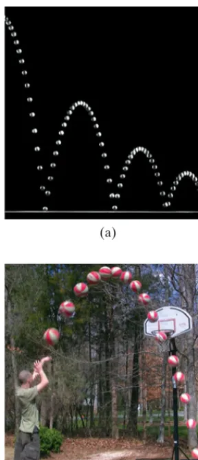
FIGURE 3;17 Photographs of (a) a bouncing ball and (b) a thrown basketball, each showing the characteristic “parabolic” path of projectile motion.
y
x
Vertical fall
Projectile motion =
x0
x
x y
y vB
v B
v B
v B
v B
v
B vB
a B gB FIGURE 3;18 Projectile motion of a small
ball projected horizontally with initial velocity The dashed black line represents the path of the object. The velocity vector is in the direction of motion at each point, and thus is tangent to the path. The velocity vectors are green arrows, and velocity components are dashed. (A vertically falling object starting from rest at the same place and time is shown at the left for comparison; is the same at each instant for the falling object and the projectile.)
vy v
B
v
B
In the horizontal direction, on the other hand, there is no acceleration (we are ignoring air resistance). With the horizontal component of velocity, remains constant, equal to its initial value, and thus has the same magnitude at each point on the path. The horizontal displacement (with ) is given by The two vector components, and can be added vectorially at any instant to obtain the velocity at that time (that is, for each point on the path), as shown in Fig. 3–18.
One result of this analysis, which Galileo himself predicted, is that an object projected horizontallywill reach the ground in the same time as an object dropped vertically. This is because the vertical motions are the same in both cases, as shown in Fig. 3–18. Figure 3–19 is a multiple-exposure photograph of an experiment that confirms this.
vB
v
B
y,
v
B
x x = vx 0t + 1
2axt2 = vx 0t.
ax = 0
vx 0,
vx,
ax = 0,
SECTION 3–5 Projectile Motion
59
x y
θ
0
= 0at this point
0 0
y
y
y0 x
v
S y
x
y x
x0
v
S
= vB
vB v B
vB vB
v B
vB
v B
vB v B
vB
v B
v B
vB g
B a B
FIGURE 3;20 Path of a projectile launched with initial velocity at angle to the horizontal. Path is shown dashed in black, the velocity vectors are green arrows, and velocity components are dashed. The figure does not show where the projectile hits the ground (at that point, projectile motion ceases).
u0 vB0
FIGURE 3;19 Multiple-exposure photograph showing positions of two balls at equal time intervals. One ball was dropped from rest at the same time the other ball was projected horizontally outward. The vertical position of each ball is seen to be the same at each instant. EXERCISE C Two balls having different speeds roll off the edge of a horizontal table at
the same time. Which hits the floor sooner, the faster ball or the slower one?
EXERCISE D Where in Fig. 3–20 is (i) vB (ii) vy = 0, and (iii) vx = 0?
= 0,
If an object is projected at an upward angle, as in Fig. 3–20, the analysis is similar, except that now there is an initial vertical component of velocity, Because of the downward acceleration of gravity, the upward component of velocity gradually decreases with time until the object reaches the highest point on its path, at which point Subsequently the object moves down-ward (Fig. 3–20) and increases in the downward direction, as shown (that is, becoming more negative). As before,vxremains constant.
vy vy = 0.
vy
vy 0.
EXERCISE E Return to the Chapter-Opening Question, page 49, and answer it again now. Try to explain why you may have answered differently the first time. Describe the role of the helicopter in this example of projectile motion.
Where does the apple land? A child sits upright in a wagon which is moving to the right at constant speed as shown in Fig. 3–21. The child extends her hand and throws an apple straight upward (from her own point of view, Fig. 3–21a), while the wagon continues to travel forward at constant speed. If air resistance is neglected, will the apple land (a) behind the wagon, (b) in the wagon, or (c) in front of the wagon?
RESPONSE The child throws the apple straight up from her own reference frame with initial velocity (Fig. 3–21a). But when viewed by someone on the ground, the apple also has an initial horizontal component of velocity equal to the speed of the wagon, Thus, to a person on the ground, the apple will follow the path of a projectile as shown in Fig. 3–21b. The apple experiences no horizontal accel-eration, so will stay constant and equal to the speed of the wagon. As the apple follows its arc, the wagon will be directly under the apple at all times because they have the same horizontal velocity. When the apple comes down, it will drop right into the outstretched hand of the child. The answer is (b).
v
B
x0
v
B
x0.
vB
y0
CONCEPTUAL EXAMPLE 3;4
y
x
(b) Ground reference frame
(a) Wagon reference frame
0
0 x y0 v B
y0 vB vB
vB vx0 vB
P R O B L E M S O L V I N G
Choice of time interval
TABLE 3;2 Kinematic Equations for Projectile Motion
(ypositive upward; )
Horizontal Motion Vertical Motion†
(Eq. 2–11a) (Eq. 2–11b) (Eq. 2–11c)
†Ifyis taken positive downward, the minus (–)signs in front of gbecome signs.±
vy2 = vy 02 - 2gAy - y0B y = y0 + vy 0t- 12gt2 x = x0 + vx 0t
vy = vy 0 - gt
vx = vx 0
(ay ⴝ ⴚg ⴝ constant) (axⴝ0, vxⴝconstant)
axⴝ0, ayⴝ ⴚgⴝ ⴚ9.80m
Ⲑ
s25. Examinethe horizontal (x) and vertical (y)motions
separately. If you are given the initial velocity, you may want to resolve it into its xandycomponents.
6. List the known and unknown quantities, choosing
and or where
and using the or sign, depending on whether you choose ypositive up or down. Remember that never changes throughout the trajectory, and that at the highest point of any trajectory that returns downward. The velocity just before landing is generally not zero.
7. Think for a minute before jumping into the equations. A little planning goes a long way.Applytherelevant equations(Table 3–2), combining equations if neces-sary. You may need to combine components of a vector to get magnitude and direction (Eqs. 3–4).
vy = 0
vx
–
± g=9.80m兾s
2, ±g,
ay= –g ax=0
P
R
O
B
L
E
M
S
O
LV I
N G
Projectile Motion
Our approach to solving Problems in Section 2–6 also applies here. Solving Problems involving projectile motion can require creativity, and cannot be done just by following some rules. Certainly you must avoid just plugging numbers into equations that seem to “work.”
1. As always, read carefully; choose the object (or objects) you are going to analyze.
2. Drawa careful diagram showing what is happening to the object.
3. Choosean origin and an xycoordinate system.
4. Decide on the time interval, which for projectile motion can only include motion under the effect of gravity alone, not throwing or landing. The time inter-val must be the same for the xandyanalyses. The x
andymotions are connected by the common time, .t
TABLE 3;1 General Kinematic Equations for Constant Acceleration in Two Dimensions
xcomponent (horizontal) ycomponent (vertical)
(Eq. 2–11a)
(Eq. 2–11b)
(Eq. 2–11c) vy2 = vy 02 + 2ayAy - y0B vx2 = vx 02 + 2axAx - x0B
y = y0 + vy 0t + 12ayt2 x= x0 + vx 0t+ 12axt2
vy = vy 0 + ayt
vx = vx 0 + axt
3–6
Solving Projectile Motion Problems
We now work through several Examples of projectile motion quantitatively. We use the kinematic equations (2–11a through 2–11c) separately for the vertical and horizontal components of the motion. These equations are shown separately for thexandycomponents of the motion in Table 3–1, for the general case of two-dimensional motion at constant acceleration. Note that xandyare the respective displacements, that and are the components of the velocity, and that
and are the components of the acceleration, each of which is constant. The subscript 0 means “at t = 0.”
ay
ax vx vy
We can simplify Eqs. 2–11 to use for projectile motion because we can set
See Table 3–2, which assumes yis positive upward, so ay = –g = –9.80m兾s2.
ax = 0.
If the projection angle is chosen relative to the axis (Fig. 3–20), then and
In doing Problems involving projectile motion, we must consider a time interval for which our chosen object is in the air, influenced only by gravity. We do not consider the throwing (or projecting) process, nor the time after the object lands or is caught, because then other influences act on the object, and we can no longer set aB
= gB
.
vy 0 = v0sinu0. vx 0 = v0cosu0,
Driving off a cliff. A movie stunt driver on a motorcycle speeds horizontally off a 50.0-m-high cliff. How fast must the motorcycle leave the cliff top to land on level ground below, 90.0 m from the base of the cliff where the cameras are? Ignore air resistance.
APPROACH We explicitly follow the steps of the Problem Solving Strategy on the previous page.
SOLUTION
1. and2. Read, choose the object, and draw a diagram. Our object is the motor-cycle and driver, taken as a single unit. The diagram is shown in Fig. 3–22.
3. Choose a coordinate system. We choose the y direction to be positive upward, with the top of the cliff as The xdirection is horizontal with
at the point where the motorcycle leaves the cliff.
4. Choose a time interval. We choose our time interval to begin just as the motorcycle leaves the cliff top at position Our time interval ends just before the motorcycle touches the ground below.
5. Examine xand ymotions. In the horizontal (x) direction, the acceleration so the velocity is constant. The value of x when the motorcycle reaches the ground is In the vertical direction, the accelera-tion is the acceleraaccelera-tion due to gravity, The value of
ywhen the motorcycle reaches the ground is The initial veloc-ity is horizontal and is our unknown, the initial vertical velocity is zero,
6. List knowns and unknowns. See the Table in the margin. Note that in addition to not knowing the initial horizontal velocity (which stays constant until landing), we also do not know the time when the motorcycle reaches the ground.
7. Apply relevant equations. The motorcycle maintains constant as long as it is in the air. The time it stays in the air is determined by the ymotion—when it reaches the ground. So we first find the time using the ymotion, and then use this time value in the x equations. To find out how long it takes the motorcycle to reach the ground below, we use Eq. 2–11b (Tables 3–1 and 3–2) for the vertical (y) direction with and
or
We solve for and set
To calculate the initial velocity, we again use Eq. 2–11b, but this time for the horizontal (x) direction, with and
or
Then
which is about (roughly ).
NOTE In the time interval of the projectile motion, the only acceleration is gin the negative ydirection. The acceleration in the xdirection is zero.
60mi兾h 100km兾h
vx 0 = x
t =
90.0m
3.19s = 28.2m兾s,
x = vx 0t.
= 0 + vx 0t + 0 x = x0 + vx 0t +
1 2axt2
x0 = 0:
ax = 0
vx0,
t = B–g2y = B2(–50.0m)
–9.80m兾s2 = 3.19s. y = –50.0m:
t
y = –1 2gt2.
= 0 + 0 + 12(–g)t2 y = y0 + vy 0t + 12ayt
2
vy 0 = 0: y0 = 0
vx
t vx 0
vy 0 = 0.
vx 0;
y = –50.0m.
ay = –g = –9.80m兾s2. x = ±90.0m.
ax = 0,
x0 = 0, y0 = 0.
(t = 0)
x0 = 0
y0 = 0.
EXAMPLE 3;5
SECTION 3–6 Solving Projectile Motion Problems
61
Known Unknown
vy 0 = 0
ay = –g = –9.80m兾s2 ax = 0
y = –50.0m
t
x = 90.0m
vx0 x0 = y0 = 0
y= −50.0 m 50.0 m
=gB a B
90.0 m
+ x
+ y
A kicked football. A kicked football leaves the ground at an angle with a velocity of as shown in Fig. 3–23. Calculate (a) the maximum height, (b) the time of travel before the football hits the ground, and (c) how far away it hits the ground. Assume the ball leaves the foot at ground level, and ignore air resistance and rotation of the ball.
APPROACH This may seem difficult at first because there are so many questions. But we can deal with them one at a time. We take the ydirection as positive upward, and treat the xandymotions separately. The total time in the air is again determined by the ymotion. The xmotion occurs at constant velocity. The y com-ponent of velocity varies, being positive (upward) initially, decreasing to zero at the highest point, and then becoming negative as the football falls.
SOLUTION We resolve the initial velocity into its components (Fig. 3–23):
(a) To find the maximum height, we consider a time interval that begins just after the football loses contact with the foot until the ball reaches its maximum height. During this time interval, the acceleration is g downward. At the maximum height, the velocity is horizontal (Fig. 3–23), so This occurs at a time given
by with (see Eq. 2–11a in Table 3–2), so and
From Eq. 2–11b, with we can solve for yat this time :
The maximum height is 7.35 m. [Solving Eq. 2–11c for ygives the same result.] (b) To find the time it takes for the ball to return to the ground, we consider a different time interval, starting at the moment the ball leaves the foot
and ending just before the ball touches the ground ( again). We can use Eq. 2–11b with and also set (ground level):
This equation can be factored:
There are two solutions, (which corresponds to the initial point, ), and
which is the total travel time of the football.
(c) The total distance traveled in the xdirection is found by applying Eq. 2–11b
with , and :
NOTE In (b), the time needed for the whole trip, is double the time to reach the highest point, calculated in (a). That is, the time to go up equals the time to come back down to the same level (ignoring air resistance).
t = 2vy0兾g = 2.45s, x = vx0t = (16.0m兾s)(2.45s) = 39.2m.
t = 2.45s
x0 = 0, ax = 0, vx0 = 16.0m兾s
t = 2vy g0 = 2(12.0m兾s)
A9.80m兾s2B = 2.45s,
y0
t = 0
tA1
2gt - vy 0B = 0.
0 = 0 + vy 0t -1 2gt2. y = y0 + vy 0t - 1
2gt2
y = 0
y0 = 0
y = 0
y0 = 0B
At = 0,
= vy 0 2
g
-1 2
vy 20 g =
vy 20
2g =
(12.0m兾s)2
2A9.80m兾s2B = 7.35m. y = vy 0t
-1 2gt2
(t = vy0兾g) y0 = 0,
t = vy g0 = (12.0m兾s)
A9.80m兾s2B = 1.224s L 1.22s.
vy 0 = gt vy = 0
vy = vy 0 - gt
vy = 0.
vy 0 = v0sin 37.0° = (20.0m兾s)(0.602) = 12.0m兾s. vx 0 = v0cos 37.0° = (20.0m兾s)(0.799) = 16.0m兾s
20.0m兾s,
u0 = 37.0° EXAMPLE 3;6 P H Y S I C S A P P L I E D
Sports
FIGURE 3;23 Example 3–6.
37.0°
y = 0at this point
0
y v B v B
v B
x0 vB y0
v B
0 vB
v B
v B
=gB a B
x
P R O B L E M S O L V I N G
y= 0 v0
y d
FIGURE 3;24 Example 3–7.
SECTION 3–6 Solving Projectile Motion Problems
63
EXERCISE F In Example 3–6, what is (a) the velocity vector at the maximum height, and (b) the acceleration vector at maximum height?
The wrong strategy. A boy on a small hill aims his water-balloon slingshot horizontally, straight at a second boy hanging from a tree branch a distance daway, Fig. 3–24. At the instant the water balloon is released, the second boy lets go and falls from the tree, hoping to avoid being hit. Show that he made the wrong move. (He hadn’t studied physics yet.) Ignore air resistance.
RESPONSE Both the water balloon and the boy in the tree start falling at the same instant, and in a time they each fall the same vertical distance
much like Fig. 3–19. In the time it takes the water balloon to travel the horizontal distanced, the balloon will have the same yposition as the falling boy. Splat. If the boy had stayed in the tree, he would have avoided the humiliation.
y = 1 2gt
2,
t
CONCEPTUAL EXAMPLE 3;7
Level Horizontal Range
The total distance the football traveled in Example 3–6 is called the horizontal
rangeR. We now derive a formula for the range, which applies to a projectile that lands at the same level it started : that is, (see Fig. 3–25a). Looking back at Example 3–6 part (c), we see that where (from
partb) Thus
[ ]
where and This can be rewritten, using the
trigon-ometric identity (Appendix A or inside the rear cover):
[only if ]
Note that the maximum range, for a given initial velocity is obtained when takes on its maximum value of 1.0, which occurs for so
The maximum range increases by the square of so doubling the muzzle velocity of a cannon increases its maximum range by a factor of 4.
When air resistance is important, the range is less for a given and the maxi-mum range is obtained at an angle smaller than 45°.
v0,
v0,
u0 = 45° for maximum range, and Rmax = v02兾g.
2u0 = 90°;
sin 2u
v0,
y (final) = y0
R = v0 2
sin 2u0
g .
2 sinucosu = sin 2u
vy0 = v0sinu0. vx0 = v0cosu0
y = y0 R = vx0t = vx0¢
2vy0 g ≤ =
2vx0vy0
g =
2v02sinu0cosu0
g ,
t = 2vy0兾g.
x = R = vx0t y (final) = y0
(y0)
Range of a cannon ball. Suppose one of Napoleon’s cannons had a muzzle speed, of At what angle should it have been aimed (ignore air resistance) to strike a target 320 m away?
APPROACH We use the equation just derived for the range, with
SOLUTION We solve for in the range formula:
We want to solve for an angle that is between 0° and 90°, which means in this equation can be as large as 180°. Thus, is a solution, so .
But is also a solution (see Appendix A–7), so
can also be . In general we have two solutions (see Fig. 3–25b), which in the present case are given by
Either angle gives the same range. Only when (so ) is there a single solution (that is, both solutions are the same).
u0 = 45°
sin 2u0 = 1 u0 = 30.3° or 59.7°.
u0 = 59.7° u0
2u0 = 180° - 60.6° = 119.4°
u0 = 30.3°
2u0 = 60.6°
2u0 u0
sin 2u0 = Rg
v02 =
(320m)A9.80m兾s2B
(60.0m兾s)2 = 0.871. sin 2u0
R = 320m.
R = v02sin 2u0兾g,
60.0m兾s.
v0,
EXAMPLE 3;8
y= 0 again here (wherex=R)
y
x x0= 0
y0= 0
0
(b)
60°
30°
y
x (a)
R
45°
θ
FIGURE 3;25 (a) The range Rof a projectile. (b) There are generally two angles that will give the same range. If one angle is the other is
Example 3–8.
u02= 90° - u01. u01, u0
A punt. Suppose the football in Example 3–6 was punted, and left the punter’s foot at a height of 1.00 m above the ground. How far did the football travel before hitting the ground? Set
APPROACH The only difference here from Example 3–6 is that the football hits the ground belowits starting point of That is, the ball hits the ground at See Fig. 3–26. Thus we cannot use the range formula which is valid only if As in Example 3–6,
SOLUTION With and (see Example 3–6), we use theyversion of Eq. 2–11b with
and obtain
We rearrange this equation into standard form so we can use the quadratic formula:
The quadratic formula (Appendix A–4) gives
The second solution would correspond to a time prior to the kick, so it doesn’t apply. With for the time at which the ball touches the ground, the horizontal distance the ball traveled is (using from Example 3–6):
Our assumption in Example 3–6 that the ball leaves the foot at ground level would result in an underestimate of about 1.3 m in the distance our punt traveled.
x = vx0t = (16.0m兾s)(2.53s) = 40.5m. vx0 = 16.0m兾s
t = 2.53s
= 2.53s or –0.081s.
t = 12.0m兾s63(–12.0m兾s)
2 - 4A4.90m兾s2B(–1.00m)
2A4.90m兾s2B
A4.90m兾s2Bt2 - (12.0m兾s)t - (1.00m) = 0.
Aax2 + bx + c = 0B –1.00m = 0 + (12.0m兾s)t - A4.90m兾s2Bt2.
y = y0 + vy0t -1 2gt2,
ay = –g,
vy0 = 12.0m兾s y = –1.00m
u0 = 37.0°. v0 = 20.0m兾s,
y (final) = y0.
y = –1.00m.
y0 = 0.
x0 = 0, y0 = 0.
EXAMPLE 3;9 P H Y S I C S A P P L I E D
Sports
P R O B L E M S O L V I N G
Do not use any formula unless you are sure its range of validity fits the problem; the range formula does
not apply here because y Z y0
Ground
y
x y0 = 0
y = −1.00 m FIGURE 3;26 Example 3–9: the
football leaves the punter’s foot at and reaches the ground where y = –1.00m.
y = 0,
3–7
Projectile Motion Is Parabolic
We now show that the path followed by any projectile is a parabola, if we can ignore air resistance and can assume that is constant. To do so, we need to find
yas a function of xby eliminating between the two equations for horizontal and vertical motion (Eq. 2–11b in Table 3–2), and for simplicity we set
From the first equation, we have and we substitute this into the second one to obtain
(3;6)
We see that yas a function of xhas the form
whereAandBare constants for any specific projectile motion. This is the standard equation for a parabola. See Figs. 3–17 and 3–27.
The idea that projectile motion is parabolic was, in Galileo’s day, at the fore-front of physics research. Today we discuss it in Chapter 3 of introductory physics!
y = Ax - Bx2
,
y = ¢vyvx0 0≤x - ¢
g
2vx20 ≤x2
.
t = x兾vx0, y = vy0t
-1 2gt2. x = vx0t
x0 = y0 = 0 :
t g
B
*
SECTION 3–8 Relative Velocity
65
3–8
Relative Velocity
We now consider how observations made in different frames of reference are related to each other. For example, consider two trains approaching one another, each with a speed of with respect to the Earth. Observers on the Earth beside the train tracks will measure for the speed of each of the trains. Observers on either one of the trains (a different frame of reference) will mea-sure a speed of for the train approaching them.
Similarly, when one car traveling passes a second car traveling in the same direction at the first car has a speed relative to the second car of
When the velocities are along the same line, simple addition or subtraction is sufficient to obtain the relative velocity. But if they are not along the same line, we must make use of vector addition. We emphasize, as mentioned in Section 2–1, that when specifying a velocity, it is important to specify what the reference frame is.
When determining relative velocity, it is easy to make a mistake by adding or subtracting the wrong velocities. It is important, therefore, to draw a diagram and use a careful labeling process. Each velocity is labeled by two subscripts: the first refers to the object, the second to the reference frame inwhich it has this velocity. For example, suppose a boat heads directly across a river, as shown in Fig. 3–28. We let be the velocity of the Boat with respect to the Water. (This is also what the boat’s velocity would be relative to the shore if the water were still.) Similarly, is the velocity of the Boat with respect to the Shore, and is the velocity of the Water with respect to the Shore (this is the river current). Note that is what the boat’s motor produces (against the water), whereas is equal to plus the effect of the current, Therefore, the velocity of the boat relative to the shore is (see vector diagram, Fig. 3–28)
(3;7)
By writing the subscripts using this convention, we see that the inner subscripts (the two W’s) on the right-hand side of Eq. 3–7 are the same; also, the outer subscripts on the right of Eq. 3–7 (the B and the S) are the same as the two subscripts for the sum vector on the left, By following this convention (first subscript for the object, second for the reference frame), you can write down the correct equation relating velocities in different reference frames.†
Equation 3–7 is valid in general and can be extended to three or more velocities. For example, if a fisherman on the boat walks with a velocity rela-tive to the boat, his velocity relarela-tive to the shore is The equations involving relative velocity will be correct when adjacent inner subscripts are identical and when the outermost ones correspond exactly to the two on the velocity on the left of the equation. But this works only with plus signs (on the right), not minus signs.
It is often useful to remember that for any two objects or reference frames, A and B, the velocity of A relative to B has the same magnitude, but opposite direction, as the velocity of B relative to A:
(3;8)
For example, if a train is traveling relative to the Earth in a certain direction, objects on the Earth (such as trees) appear to an observer on the train to be traveling 100km兾hin the opposite direction.
100km兾h
vBBA = –vBAB.
vBFS = vBFB + vBBW + vBWS.
vBFB v
B
BS. vBBS = vBBW + vBWS.
vBWS.
vBBW vBBS
v
B
BW vBWS
v
B
BS vBBW
90km兾h - 75km兾h = 15km兾h. 75km兾h,
90km兾h 160km兾h
80km兾h 80km兾h
†We thus can see, for example, that the equation is wrong: the inner subscripts
are not the same, and the outer ones on the right do not correspond to the subscripts on the left.
VBBW= V
B BS+ V
B WS
E N
W
S
BS BW
WS vB
vB v
B
θ
River current
FIGURE 3;28 A boat heads north directly across a river which flows west. Velocity vectors are shown as green arrows:
As it crosses the river, the boat is dragged downstream by the current.
(river current). respect to the Shore v
B
WS = velocity of Water with respect to the Water, v
B
BW = velocity of Boat with respect to the Shore, v
B
Heading across the river. The same boat
now heads directly across the river whose current is still (a) What is the velocity (magnitude and direction) of the boat relative to the shore? (b) If the river is 110 m wide, how long will it take to cross and how far downstream will the boat be then?
APPROACH The boat now heads directly across the river and is pulled down-stream by the current, as shown in Fig. 3–30. The boat’s velocity with respect to the shore, is the sum of its velocity with respect to the water, plus the velocity of the water with respect to the shore, just as before,
SOLUTION (a) Since is perpendicular to we can get using the theorem of Pythagoras:
We can obtain the angle (note how is defined in Fig. 3–30) from:
A calculator with a key INV TAN or ARC TAN or gives
Note that this angle is not equal to the angle calculated in Example 3–10. (b) The travel time for the boat is determined by the time it takes to cross the river. Given the river’s width we can use the velocity component in the direction of D, Solving for we get
The boat will have been carried downstream, in this time, a distance
NOTE There is no acceleration in this Example, so the motion involves only constant velocities (of the boat or of the river).
d = vWSt = (1.20m兾s)(59.5 s) = 71.4m L 71m.
59.5s.
t = 110m兾1.85m兾s =
t,
vBW = D兾t.
D = 110m,
= 33.0°.
tan–1(0.6486) u =
tan–1
tanu = vWS兾vBW = (1.20m兾s)
兾
(1.85m兾s) = 0.6486.u
vBS = 3vBW2 +vWS2 = 3(1.85m兾s)2+(1.20m兾s)2 = 2.21m兾s. vBS
v
B
WS, v
B
BW vBBS = vBBW + vBWS.
v
B
WS:
vB
BW, v
B
BS,
1.20m兾s.
AvBW = 1.85m兾sB EXAMPLE 3;11
BS BW
WS v B
vB v
B
θ
River current
FIGURE 3;30 Example 3–11. A boat heading directly across a river whose current moves at 1.20m兾s.
A quantity such as velocity, that has both a magnitude and a direction, is called a vector. A quantity such as mass, that has only a magnitude, is called a scalar. On diagrams, vectors are represented by arrows.
Addition of vectors can be done graphically by placing the tail of each successive arrow at the tip of the previous one. The sum, or resultant vector, is the arrow drawn from the tail of the first vector to the tip of the last vector. Two vectors can also be added using the parallelogram method.
Vectors can be added more accurately by adding their componentsalong chosen axes with the aid of trigonometric functions. A vector of magnitude Vmaking an angle with the
axis has components
(3;3) Vx = Vcosu,
Vy = Vsinu.
±x u
Given the components, we can find a vector’s magnitude and direction from
(3;4)
Projectile motionis the motion of an object in the air near the Earth’s surface under the effect of gravity alone. It can be analyzed as two separate motions if air resistance can be ignored. The hori-zontal component of motion is at constant velocity, whereas the vertical component is at constant acceleration, just as for an object falling vertically under the action of gravity.
The velocity of an object relative to one frame of refer-ence can be found by vector addition if its velocity relative to a second frame of reference, and the relative velocityof the two reference frames, are known.
g
B,
V = 3Vx2 + Vy2,
tanu = Vy Vx.
Summary
Heading upstream. A boat’s speed in still water is . If the boat is to travel north directly across a river whose westward current has speed at what upstream angle must the boat head? (See Fig. 3–29.)
APPROACH If the boat heads straight across the river, the current will drag the boat downstream (westward). To overcome the river’s current, the boat must have an upstream (eastward) component of velocity as well as a cross-stream (northward) component. Figure 3–29 has been drawn with the velocity of theBoat relative to the Shore, pointing directly across the river because this is where the boat is supposed to go. (Note that )
SOLUTION Vector points upstream at angle as shown. From the diagram,
Thus u = 40.4°, so the boat must head upstream at a 40.4° angle. sinu = vWS
vBW =
1.20m兾s
1.85m兾s = 0.6486.
u vB
BW
vBBS = vBBW + vBWS.
vBBS,
vWS = 1.20m兾s,
1.85m兾s
vBW = EXAMPLE 3;10
E N W
S
BS BW
WS
v B
vB
v B
θ
River current
MisConceptual Questions
67
1. One car travels due east at and a second car travels north at Are their velocities equal? Explain. 2. Can you conclude that a car is not accelerating if its
speed-ometer indicates a steady Explain.
3. Give several examples of an object’s motion in which a great distance is traveled but the displacement is zero.
4. Can the displacemen