The Effect of Fe Additive on Plastic Deformation for Crush-Boxes with Closed-Cell Metal
Foams, Part I: Al-Composite Foam Compression Response
S.M.H.Mirbagheri
*and J. Khajehali
Department of Mining and Metallurgical engneering, Amirkabir University of Technology, Tehran, Iran
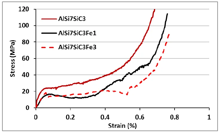
Abstract: In this study, the effect of Fe–intermetallic compounds on plastic deformation of closed-cell composite Aluminum Foam as the filler of thin-walled tubes is investigated. Composite foams of AlSi7SiC3 and AlSi7SiC3-(Fe) as a closed cell were synthesized through powder metallurgy foaming method. Macro and Micro structures of the produced foams revealed a non-homogenous cell which is dependent on Fe-rich intermetallic compounds. The cellular structure of AlSi7SiC3 foam shows a non-uniform and small size of bubbles with a few central big voids in comparison with the AlSi7SiC3-(Fe) foams. The analysis of EDAX (Energy Dispersive Analysis of X-rays) indicate that there are (α+β)-Fe- intermetallic compound within foams with Fe < 2 wt. %, and (α+δ)-Fe-intermetallic compound for the foams with Fe > 2 wt. %, in which their presence depend on the cooling rate during the solidification of liquid foams. The stress-strain curve of the AlSi7SiC3 foam shows a smooth plastic deformation behavior in the plastic region, throughout the compression tests. However, by increasing the weight percent of Fe from 1 up to 3%, the curve shows some variation at the slope of curves within the plastic zone. The results obtained indicated that all of the compression response is due to the micro-porosity in plateau region and the presence of the Fe-Al-Si-intermetallic within the cell wall revealed that both of them have the role of a stress concentration point during the compressive loading.
Keywords: Metal foam, plastic deformation, compression response, absorption energy, Fe-Al-Si-intermetallic compound
1. Introduction
IJMF, Iranian Journal of Materials Forming, Volume 1, Number 1 April 2014
focused on compressive properties of the Al composite foams with reinforcing particles such as Al2O3 and
SiC [12-14]. However, investigations on the effect of the elements with high melting point temperatures with respect to the matrix alloy melting point on the compressive properties are very few, especially when the combination of both the high melting point elements powder (such as Fe and Si) and the reinforcement particles are considered (as like SiC and TiB2). Recently, it is reported that the compressive
stress–strain curve of AlSi9Mg foams is smooth with hardening-strain, whereas AlSi9Mg–SiC composite foams are not smooth and exhibit some serrations, which often is associated with the hardening-strain [15]. Therefore, in the present investigation, the effect of Fe and SiC on micro-structural and behavior of plastic deformation for Al-Si foam as filler of crush-boxes, under the condition of quasi-static uni-axial compression load has been evaluated. Moreover, the mechanism of Fe powder addition on the elimination of strain hardening during plastic deformation has been described based on the creation of the ductile or brittle inter-metallic compounds and the micro-porosity into the Al-Si-SiC foam cellular structure
2. Experimental procedures
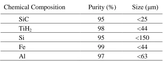
The present investigation makes use of powder mixtures such as Fe, Al-Si, SiC, and TiH2 powders as a
high melting point stabilizer, matrix alloy, reinforcement, and blowing agent for foam production process, respectively. Table (1) shows the characteristics of each powder. In order to assess the Fe additive on the cellular structure and the mechanical properties during plastic deformation, three types of composite foams namely AlSi7SiC3, AlSi7SiC3Fe1, and AlSi7SiC3Fe3 were designed and synthesized using powder metallurgy method. In order to produce the precursor, the powders mixture were then mixed with 1wt.% TiH2 and, after cold iso-static was pressed into green cylinders with 63 mm diameter, it was hot
extruded at 450 ◦C with the extrusion ratio of 63/14. Therefore, three types of precursors; AlSi7SiC3, AlSi7SiC3Fe1, and AlSi7SiC3Fe3 in each hot extrude will be prepared.
Table 1. Consume powders Characteristics
Chemical Composition Purity (%) Size (μm)
SiC 95 <25
TiH2 98 <44
Si 95 <150
Fe 99 <44
Al 97 <63
The foaming treatment was carried out for all precursors in a resistance electrical furnace at 700 ◦C using several thin-walled tubs as mould. The tubular moulds with thickness of 1 mm, and outside diameters of 16, 22 and 35 mm were cut with the height of 1.5 times of their diameters, respectively. Then all the tubes were preheated to 700 ◦C. The obtained precursors from the hot extrusion were cut and put into the tubes separately and was held in the foaming temperature for 8-10 minutes, and immediately cooled through the forced air.
order to identify the Composite Metal Foam samples, they were coded as "CMF-Z-X-Y”. Each code includes three parts: "Z", "X" and "Y". The letter "Z" refers to geometry of moulds (S=square, C=circle) and the letter "X" refers to diameter of foam cross-section as a millimeter (16 or 22, or 35mm), and "Y" indicates weight percent amount of the Fe powder in foams (Y= 0% or 1% or 3%).
However, in this part, all moulds had a circle cross-section. The "Z=C" in codes then were deleted and the obtained microstructures were investigated using an optical microscope and an X30 Philips scanning electron microscope was operated at 20 KV. Compositional spot analyses were performed at the interface of the inter-metallic compounds and the matrix alloy using an Energy Dispersive X-ray Analysis (EDXA) facility in the SEM.
3. Results and Discussions
3.1. Phases, compounds and cellular structure
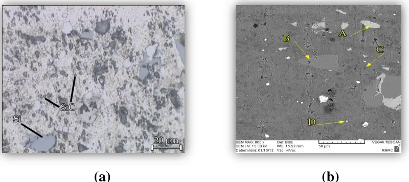
Fig.1a. shows the distribution of the consumed powder particles based on Table (1) in the produced precursors.
(a) (b)
Figure 1. Metallography of precursors and distribution of particles (types and sizes) in consumed powders; a) optical metallography, b) SEM metallography.
IJMF, Iranian Journal of Materials Forming, Volume 1, Number 1 April 2014 (a)
(b)
(c) (d)
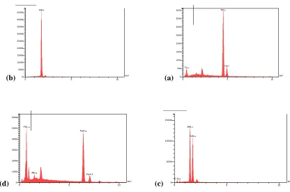
Figure 2. EDXA analysis for A, B, C, and D points in Figure 1(b).
Based on the maximum peaks, it is seemed that the particles A, B, C, and D in the precursor are TiH2,
Si, SiC, and Fe, respectively. Fig. 3 illustrates relative densities, and images of the cellular structure for AlSi7SiC3, AlSi7SiC3Fe1, and AlSi7SiC3Fe3 composite foams, which took out from the thin-walled tubes (mould) after foaming and cutting in longitude section direction versus samples codes. The relative densities of samples with CMF-22-0, CMF-22-1, and CMF-22-3 codes are 0.38, 0.35, and 0.31, respectively.
It can be seen that all the produced foams present a roughly closed-cell structure and the magnitude of pores per inch (PPI) at the cross-section of the foams was between 25-32 PPI. However, the composite foam without Fe have approximately non-uniform distribution and cell size, in comparison to the composite foams containing Fe. It is obvious from the cellular structure of the composite foams without Fe that there are significant variations in closed-cells size and cells wall thickness. In fact, there are several dispersed big voids with coarse surface in cross-section of the foams without Fe. In addition, defects such as drainage, big void, and crack are observed for the foams without Fe composite.
As it is illustrated in Fig. 3, it can be noted that as the Fe powder increases, the cell size increase as well. However, by adding Fe powder into the AlSi7SiC3 composite foam, the association with the SiC particles increases the viscosity (due to their high melting point) and thus reduces the flow-ability of molten melt, which should lead to the thickening of the cells wall. The presence of SiC particles so helps the retention of molten melt and the flow of it is hindered in all directions (the Gibbs–Marangoni effect), whereas Fe with formation of Fe-Si-Al intermetallic compounds can increase the surface tension and the capillarity. TiK TiK TiL keV 0 500 1000 1500 2000 2500 3000 3500 4000
0 5 10
SiK keV 0 5000 10000 15000 20000 25000 30000 35000 40000 45000
0 5 10
C K AlK SiK keV 0 5000 10000 15000
0 5 10
AlK FeK FeK FeL keV 0 1000 2000 3000 4000 5000 6000
Fig.3 Longitude section of the AlSi7SiC3Fe(Y) foams versus their codes and relative densities.
IJMF, Iranian Journal of Materials Forming, Volume 1, Number 1 April 2014
0 wt.% Fe
1 wt.% Fe
3wt.%Fe
(1)
(2)
(3)
X125
X250
X80
A
X4000
X6000
X5000
E
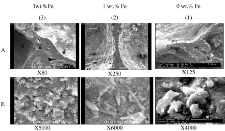
Fig.4. Substructures of closed cell foam versus wt. % Fe (columns: (1), (2), and (3)) and magnification (rows: A and E).
Table 2. Reactions and thermodynamic data in the Al-rich corner of the Al-Si-Fe system (see phase diagram of Fig.5)
Reaction-point
Reaction Temp (oC)
Reaction-line
Reaction Temp.range (oC) P1 766 P1-U1 648-751 P2 665 P1-U2 636-766 U1 648 P2-U1 648-665 U2 636 P2-U4 596-665 U3 609 U1-U3 609-648 U4 596 U2-U3 609-636 E1 576 U3-E1 576-609 - - - U4-E1 576-596
[16-17]
during transforming from the liquid’s temperature to the solids temperature (thermal path P1U2(Al)E1 on Fig.5). In the absence of Si, the dominant intermetallic phases that forms are Al
3Fe (θ-phase) and Al6Fe [16]. However, when Si is presented, the dominant phases are Al8Fe2Si
(α-phase), Al
5FeSi (β-phase), Al3FeSi (γ-phase), and Al4FeSi2 (δ-phase) based on the corner of Al-Si-Fe
phase diagram in Fig.5 [16-18].
Fig.5. Corner of Al-Si-Fe ternary phase diagram and stable intermetallic compounds.
IJMF, Iranian Journal of Materials Forming, Volume 1, Number 1 April 2014
exhibits fair bonding between the inter-metallic phases and the matrix alloy, as far as any discontinuity is not observed at the interface. Although during the foaming process, the gas is released and may accumulate at the interface of the inter-metallic phase and the matrix, the microstructure reveals a semi-strong interface, which is continuously distributed without micro-porosity, crack and gap at the inter-metallic and matrix interface. Therefore, the micro-bubbles should move to the plateau region, due to the viscosity and capillarity effects. Fig.4, image A(3) shows the object that is in agreement with reference [22]. Fig. 6 (marked P1) shows the location and compound of the inter-metallic phase in the cell structure and illustrates that inter-metallic phases tend to extend into the gas bubble.
Fig.6.Intermatallic Al-Si-Fe and EDXA results within cell wall thickness AlSi7SiC3Fe3 foam.
platelet shape is among the favored compound, which is in line with results of references [16-17]. Finally, it is concluded that during the foaming process, the increasing of Fe in the AlSi7SiC3Fe composite foams lead to the increase size of the cell and decrease the thickness of the cells walls. In addition, during solidification of the liquid foams, Al4Fe2Si- δ –platelets was formed with the strong bond. The δ – platelets tend to extend into the gas bubble and precipitate in the cell wall (due to distortion of cell walls), whereas micro-porosities dispose toward accumulation at plateau regions of cells. Both of them (the inter-metallic compound and the micro-porosities) have the roles of stress concentration zones, and they can significantly affected mechanical and physical properties of the foams such as compression test.
3.2. Compression response for metal foams
Fig. 7 shows the effect of Fe wt. % on stress-strain curves for the three composite metal foams during the compression test.
Fig.7. Stress-strain curves of the three composite metal foams, during uniaxial and quasi static plastic deformation.
strain-IJMF, Iranian Journal of Materials Forming, Volume 1, Number 1 April 2014
y = -3.8347x + 5.3779
R² = 0.9737
y = -0.2857x + 3.2447
R² = 0.9062
y = -1.8543x + 4.8452
R² = 0.9824
y = 0.1063x + 2.4419
R² = 0.1833
y = -1.9047x + 5.3321
R² = 0.9438
y = -0.3x + 3.8356
R² = 0.9415
0 1 2 3 4 5 6
0 0.5 1 1.5 2 2.5 3
Ln(S
tr
e
ss
M
P
a
)
-Ln(strain%)
AlSi7SiC3
AlSi7SiC3Fe1
AlSi7SiC3Fe3
hardening phenomenon and toughness. It seems that brittleness of AlSi7SiC3Fe-(Y) foams is due to the dispersion of the intermetallic compounds within the foam cell walls and the accumulation of micro-voids within the plateau zones, in comparison with the AlSi7SiC3 samples.
The ductile behavior of foam samples containing Fe might be attributed to the relatively more brittleness in comparison to the AlSi7SiC3 foams. Therefore, the behavior of strain-hardening exponent for all samples, during plateau plastic deformation, can be noted. The flow stress of a material is generally expressed as a function of plastic strain through equation, where "n" is the strain-hardening exponent, and "K" is the plastic strength coefficient. The variation of with for all of the composite foam at plastic deformation regions (Not elastic) are shown in Fig. 8. Moreover, the two mechanisms and their governing equations can be noted for each material in Fig. 8.
Fig.8. Plot of Ln(ζ) versus Ln(ε) for the three foams during plastic deformation in Fig.7.
0 10 20 30 40
AlSi7SiC3 AlSi7SiC3Fe1
AlSi7SiC3Fe3
30.19
23.75
19.58
En
e
rg
y
(J
/M
-3
)
Deformation Energy pre volume
Table 3. Determination of "n" and "k" coefficients of hardening-strain equation for all the samples in Fig.8
sample
code Eq(n1) Eq(n2) / n1 / n2 ln(k1) ln(k2)
Line-line
intersection
ln(ε) ln (σ)
CMF-20-0 Lnσ =1.9047Lnε + 5.3321 Lnσ =0.3Lnε +3.8356 1.91 0.30 5.33 3.83 1 3.5
CMF-20-1 Lnσ =1.8543Lnε + 4.8452 Lnσ =-0.1063Lnε +2.442 1.85 -0.1 4.84 2.44 1.11 2.7
CMF-20-3 Lnσ=3.8347Lnε + 5.3779 Lnσ=0.2857Lnε +3.2447 3.83 0.28 5.38 3.25 0.7 2.7
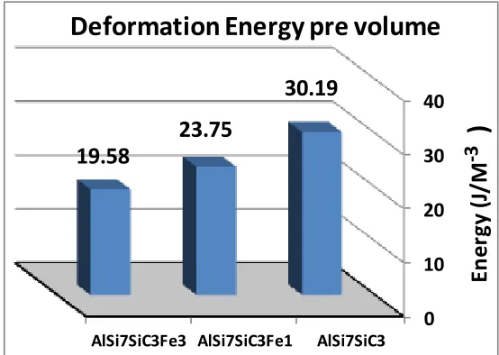
3.3. Effect of Fe on energy absorption capacity
Fig. 9 illustrates the effect of Fe additive on the energy absorption capacity at a fixed strain rate.
Fig.9. Obtained absorption energy from curves in Fig.7 during the plastic deformation of foams under uniaxial loading.
In Fig.9, the absorbed energy during the deformation plastic of composite foams is shown where W, was calculated from Equation (1):
∫ (1)
Where the upper limit of integration (εd
) is determined from cross-cut lines in Fig.8, and the
data of Table 3.
IJMF, Iranian Journal of Materials Forming, Volume 1, Number 1 April 2014
Fig.6). Therefore, for the AlSi7SiC3Fe-(Y) composite foams, which their cell wall containing (α+β) for wt. % Fe < 2 or (α+δ) for wt. % Fe > 2 (according to thermal paths on Fig.5 and Table 2), dependent on low and high cooling rate, respectively, an additional energy is absorbed at ASi7SiC3:Fe1 samples due to the presence of the concentration of stress around of the intermetallic within the cell wall (see Fig.4, and 6),as like stress intensity around of the micro-void within cell plateau region (see image A(3) in Fig.4). On the basis of the above results, it can be deduced that foams containing of Fe, the solid bubbles (with Fe-Intermetallic compounds) have a good plastic buckling, and if they have been surrounded with some micro-voids, due to suitable distribution of plastic hinge points at the walls and plateau regions, they show a wide range of the strain at a stress level approximately smooth. This behavior is more suitable for energy absorbers at the time of crash impact. Therefore the addition of Fe to the AlSi7SiC3 foam, during compression test until the densification strain, can decrease positive-slope of strain-hardening toward a smooth slop (nearly zero slop), only for foams with Fe <2 wt.% which Fe is as (α+β) intermetallic compound. However for the foams with wt. % Fe>2 wt.% and as (α+δ) intermetallic compound, the stress level during the densification strain will not be smooth.
4. Conclusions
1. Cellular structure and Micro-structure of composite foams have a significant role on the behavior of plastic deformation of the AlSi7SiC3foams and AlSi7SiC3Fe foams. In cases that foam cells walls can be thinner during the growth bubbles without the cells coalesce the absorption energy will be increased by decreasing the foams relative density.
2. During AlSi7SiC3Fe foaming processes by powder metallurgy route, some intermetallic such as α+β and α+δ are formed depending on the cooling rate and the percent of Fe element, which strongly affected on mechanical and physical properties. Results showed α+δ formed at high cooling rate and Fe percent of more than 2 wt. %, and α+β formed at lower cooling rate and Fe percent less than 2 wt. %.
3. During foaming process, the micro-voids are accumulated within the cell plateau region (see Fig.4) and the flack Fe-intermetallic compounds are moved to the cell thin walls as a perpendicular (see Fig.6), and thus both of them act as the stress concentration pointes.
4. Fe additive in the AlSi7SiC3 composite foams affected on the hardening-strain exponent. In case 1wt. %Fe the hardening-strain exponent "n2" is near to zero that is related to the foam with 3wt. %Fe. It is clear that "n2≈0" referred to the plastic deformation without work-hardening. In this condition, the plateau stress versus strain is alike a horizontal line. Therefore, the AlSi7SiC3Fe1 rather than the AlSi7SiC3Fe3 is due to the hardening-strain exponent that is near to zero and the higher energy absorption (approximately 21%) of the AlSi7SiC3Fe1.
5. References
[1] J. Baumeister, J. Banhart, M.Weber, Aluminum foams for transport industry, Materials & & Design
,
18(4/6), (1997) 217-220.[2] T. Mukai, T. Miyoshi, S. Nakano, H. Somekawa, K. Higashi, Compressive response of a closed-cell Aluminum foam at high strain rate, Scripta Materialia, 54 (2006) 533–537.
[4] A.G. Evans M.F. Ashby, N.A. Fleck, L.J. Gibson, J.W. Hutchinson, H.N.G. Wadley, Metal foams: A design guide, Elsevier, UK, (2000), chapter: 11.
[5] M. F. Ashby L. J. Gibson, Cellular Solids: Structure and Properties. Solid State Science., UK: Cambridge, (1997), chapter:4.
[6] W. abramowicz and T. Wierzbicki, Axial crushing of foam-filled columns, Journal of. Mechanical Science, 30, Issues 3-4 (1988) 263-271.
[7] M. Langseth, A.G. Hanssen, and O.S. Hopperstad, Optimum design for energy absorption of square Aluminum columns with Aluminum foam filler, International Journal of Mechanical Sciences, 43 (2001)153-176.
[8] A.F. Bastawros, H. Bart-Smith, and A.G. Evans, Experimental analysis of deformation mechanisms in a closed-cell aluminum alloy foam. Journal of the Mechanics and Physicsof Solids, 48 (2000) 301-322.
[9] A.K. Toksoy and M. Guden, Partial A: Foam filling of commercial 1050H14 crash boxes: the effect box column thickness and foam relative density on energy absorption, Thin-walled structures, 48(2010) 482-494.
[10] W. Yan, E. Durif, Y. Yamada and C. Wen, Crushing Simulation of Foam-Filled Aluminum Tubes, Materials Transactions, 48, No. 7 (2007) 1901-1906.
[11] W. Deqing and S. Ziyuan, Effect of ceramic particles on cell size and wall thickness of aluminum foam,
Materials Science and EngineeringA, 361 (2003) 45–49.
[12] P. Mondal, M.D. Goel, and S. Das, Effect of strain rate and relative density on aluminum-fly ash composite foam, Materials & Design 30 (2008) 1268–1274.
[13] M.J. Khajeali, Compressive response of the composite metallic foam filled-tubes and effective parameters,
M.Sc. Thesis, Amirkabir University, (2011).
[14] A. Daoud, ,Compressive response and energy absorption of foamed A359–Al2O3 particle composites, Journal
of Alloys and Compounds, 486 (2009) 597–605.
[15] Y. Luo, S. Yu,W. Li, J. Liu, and M. Wei,Compressive behavior of SiCp/AlSi9Mg composite foams, Journal of Alloys and Compounds 460 (2008)294–298.
[16] S. Lee, B. Kim and S. Lee, Prediction of Solidification Paths in Al-Si-Fe Ternary System and Experimental Verification: Part I. Fe-Containing Hypoeutectic Al-Si Alloys, Materials Transactions, Vol. 52, No. 5 (2011) 1053-1062.
[17]. Sanghwan Lee, Bonghwan Kim and Sangmok Lee, Prediction of Solidification Paths in Al-Si-Fe Ternary System and Experimental Verification: Part II. Fe-Containing Eutectic Al-Si Alloys, Materials Transactions, 52, No. 6 (2011)1308-1315.
[18] E. Amsterdam, P. R. Onck, and J. TH. M. Dehosson, Fracture and microstructure of open cell Aluminum foam,
Journal of Materials Science, 40 (2005) 5813–5819
[19] G. Mrówka-Nowotnik, J. Sieniawski, and M. Wierzbiñska, Intermetallic phase particles in 6082 aluminum alloy, Archives of Materials Science and Engineering, 28, Issue 2 (2007) 69-76.
[20] E. Amsterdam, N. Babcsán, Jeff T.M. De Hosson, P.R. Onck, and J. Banhart, Fracture behavior of metal foams made of recycled MMC by the melt route, Materials Transactions, 47(6) (2006) 2219-2222.
[21] L. Sweet, S.M. Zhu, S.X. Gao, J.A. Taylor, and M,A. Easton, The effect of iron content on the Iron-containing intermetallic phases in a cast 6060 Aluminum alloy, Metallurgical and materials transaction A, 42A (2011)1737-17-49.
IJMF, Iranian Journal of Materials Forming, Volume 1, Number 1 April 2014
[23] Anton Gorny, Characterization of Major Intermetallic Phases in solidified Al-xSi-yFe-zSr alloy, Ph.D. thesis (open accesses), McMaster University, (2012).
[24] M. Timpel, N. Wanderka , R. Grothausmann , and J. Banhar , Distribution of Fe-rich phases in eutectic grains of Sr-modified Al-10wt%Si-0.1wt% Fe casting alloy,
Journal of Alloys and Compounds, 558(2013) 18–25.