Operation and Control Analysis of Modular
Multilevel Converter for VSC-HVDC
Application
Huancheng Lin and Zhixin Wang
Dept. of Electrical Engineering, Shanghai Jiao Tong University, 800 Dongchuan Road Minhang District, Shanghai, China
Email: [email protected]
Abstract—Due to the scalability and flexibility in power transmission, the Modular Multilevel Converter (MMC) receives a widespread favor since its advent. The popularization of the MMC will continuously promote the developments in renewable energy grid connecting and flexible High Voltage Direct Current transmission (HVDC) system. In this paper, an overview of the most recent effort associated with the technical challenges of the MMC is provided, and a brief summary on the design and control of the MMC is made. The features of different submodule topologies of the MMC are concluded with a comparison in this paper. Multiple simulation techniques for the MMC, which are suitable for electromagnetic and electromechanical transient respectively, are reviewed in this paper. This paper also makes an overview of the control methods for the MMC operation including pre-charge, power regulation, circulating current control and capacitor voltage balancing. On this basis, the future trends of further studies and developments for the MMC are proposed.
Index Terms—Modular Multilevel Converter (MMC), submodule (SM), capacitor voltage balancing, circulating current control, modulation technique, VSC-HVDC
I. INTRODUCTION
The Modular Multilevel Converter (MMC) is widely regarded as an emerging topology, and lots of attentions have been attracted to the applications of MMC. The MMC is constructed with cascaded structure of modular submodule (SM), bringing the features of flexibility and scalability. Compared with conventional two-level voltage source converter, the MMC shows fascinating characteristics of low harmonic component, high power quality, low ac filter requirement and excellent suitability in high voltage conditions, and therefore is more and more widely applied to renewable energy grid connecting and long-distance High Voltage Direct Current transmission (HVDC) system.
The paper is to make a systematic summary for the latest work focusing on the technical challenges, and offer a better comprehension on the present situations and future trends of MMC. The review of recent significant research progress for the MMC, includes the aspects of
Manuscript received February 13, 2017; revised June 29, 2017.
topology, modeling, operation and control, as well as design and optimization analysis methods.
II. TOPOLOGY OF THE MMC
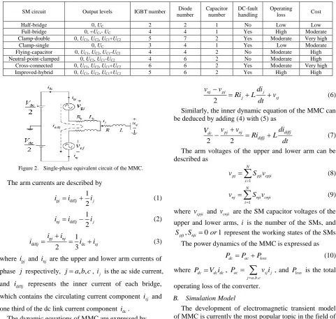
This paper mainly pays attention to the VSC-HVDC system utilizing double-star connection structure as shown in Fig. 1, in which the MMC consists of two arms in each phase unit and each arm has N cascaded submodules (SMs) and one series arm inductor. Under this premise, different SM topologies can be approximately divided into the different types, and Table I provides a comparison of different SM circuits, in terms of device amount, output voltage levels, dc fault handling capacity, operating loss and manufacturing cost. The dc-side fault handling ability is an important feature for SM design, however, it needs larger numbers of device and thus increases the cost. Another factor that will increase the cost is to raise the output voltage levels, which also adds to the device number.
Figure 1. Block diagram of the MMC system.
III. MODELING OF THE MMC
that can reflect the general operating rules of the converter are in a pressing need. The construction of an accurate model is also a cornerstone for the study of the operating features, the selection of the main circuit parameters and the design of the control system.
A. Mathematical Model
This paper presents the mathematical model of the MMC which is most widely used in proposed literatures [1], [2]. The single phase equivalent circuit of the MMC is shown in Fig. 2, where the SM is of the FB-SM circuit andRbis the equivalent loss resistance of each bridge.
TABLEI. COMPARISON OF VARIOUS SMCIRCUITS
SM circuit Output levels IGBT number number Diode Capacitor number DC-fault handling Operating loss Cost
Half-bridge 0, UC 2 2 1 No Low Low
Full-bridge 0, +UC,- UC 4 4 1 Yes High Moderate
Clamp-double 0, UC1, UC2, UC1+UC2 5 7 2 Yes Moderate Very high
Clamp-single 0, UC 3 4 1 Yes Low Moderate
Flying-capacitor 0, UC1, UC2, UC1-UC2 4 4 2 No Moderate High
Neutral-point-clamped 0, UC2, UC1-UC2 4 6 2 No Moderate High
Cross-connected 0, UC1, UC2, UC1+UC2 6 6 2 Yes Moderate Very high
Improved-hybrid 0, UC1, UC2, UC1+UC2 5 6 2 Yes High High
Figure 2. Single-phase equivalent circuit of the MMC.
The arm currents are described by
p diff
1 2
j j j
i i i (1)
n diff
1 2
j j j
i i i (2)
p n
diff dc z
1
2 3
j j
j j
i i
i i i (3)
where ipj and inj are the upper and lower arm currents of
phase
j
respectively, ja b c, , , ij is the ac side current,and idiffj represents the inner current of each bridge,
which contains the circulating current component izj and
one third of the dc link current component idc. The dynamic equations of MMC are expressed by
2
pj dc
pj pj sj
di V
v Ri L v
dt
(4)
2
nj dc
nj nj sj
di V
v Ri L v
dt
(5)
where vpj and vnj represents the upper and lower arm
voltage, and vsj is the phase voltage of the ac side.
Subtracting (5) from (4), the phase voltage equation of the MMC can be deduced as
2
nj pj j
j sj
v v di
Ri L v
dt
(6)
Similarly, the inner dynamic equation of the MMC can be deduced by adding (4) with (5) as
2 2
pj nj diffj
dc
diffj
v v di
V
Ri L
dt
(7)
The arm voltages of the upper and lower arm can be described as
1
N
pj pji cpji i
v S v
(8)1
N
nj nji cnji i
v S v
(9)where vcpji and vcnji are the SM capacitor voltages of the
upper and lower arms, i is the number of the SMs, and
, 0 1
pji nji
S S or represent the working states of the SMs.
The power dynamics of the MMC is expressed as
dc ac loss
P P P (10)
where Pdc V idc dc,
, ,
ac sj j
j a b c
P v i
, and Ploss is the totaloperating loss of the converter.
B. Simulation Model
the modeling of half-bridge type MMC. Fig. 3 shows the modeling steps for a submodule for universal equivalent model and Thevenin equivalent model respectively.
Fig. 4 shows the overview of various MMC simulation techniques. The electromechanical transient and real-time simulation for MMC based system will become the focus in the field of MMC modeling gradually in the future, because it is closer to the requirement of large system analysis and engineering practice.
IV. OPERATION OF THE MMC
A. Pre-charge and Startup Scheme
Distributed capacitors in MMC induce a more complicated startup process, and the behaviors of an MMC under different operation conditions is different from traditional two-level converters [3]. The conventional MMC pre-charge strategy and related detailed specifications are reported, in which the submodules are charged one by one with a DC storage capacitor. Jianzhong Xu et al. point out that the pre-charge method is uneconomic in time cost and can’t guarantee the voltages of SMs in a stable value [4].
Two strategies for the pre-charge process are proposed in [4], with which the voltages of SMs and the parameters of external dc voltage sources are easy to get adjusted. A self-start control strategy for the CD-SM based MMC-HVDC link is put forward in [5] by Yinglin Xue et al., in which a simple grouping sequentially controlled charge (GSCC) method is used to fully charge the submodule capacitors and makes each capacitor share sufficient stored energy. Binbin Li et al. present two closed-loop methods in [6] to pre-charge the SMs with constant charging current and less startup time, moreover, by using these ways the auxiliary power supply is not necessary and the inrush current can be eliminated. However, this method needs special-designed capacitor balancing and reference generation algorithms, and a fast transition between startup and the normal operation is demanded to avoid overcharging of capacitors. Under this premise, Xiaojie Shi et al. propose a startup strategy without losing voltage control precision, which incorporates an averaging capacitor voltage loop with a small-signal model based feedforward control. Tian Kai et al. in [7] present a simple and cost-effective pre-charge method with a low-voltage dc source instead of a
high-voltage one, and this method is afforded flexibility due to the characteristics of the boost circuit.
arm I 1 SM SM1 U 2 SM SM2 U arm I SMn SMn U arm I arm I + sum U sum SM 1 = N i i UU + SM U + 1 T 2 T 1 D 2 D C + C I SM U R2
1 R
0
D RC SEQ
R SEQ U + SM U C
I ISM
(a)
(b)
Figure 3. Modeling steps for a submodule (a) universal equivalent model, (b) Thevenin equivalent model.
MMC Simulation Techniques Offline Simulation Real-Time Simulation Electromagnetic Transient Simulation Electromechanical Transient Simulation Detailed Model Controlled-Source Based Model Thevenin Equivalent Model Arm Equivalent Model
Mean Value Model
Semi-Physical Simulation Equivalent Network Model Continuous Model Enhanced Equivalent Model
Microsecond-Level Simulation
Millisecond-Level Simulation
Figure 4. Overview of various MMC simulation techniques.
B. Power Control Strategy
With given reference voltages, signal modulation technologies are required to generate trigger signal for switching devices. The typical overall control scheme is shown in Fig. 5.
abc PI 0L + + + + + j i d i q i d i q i dq 0L PI PI PI PI PI dc V dc V P P ac V ac V Q Q MMC Internal Controller + + + + Modulation MMC S arm N
Table II provides a comparison of different MPC strategies in terms of calculated states number with different arm SM number N, cost function number, weighting factor tuning effort, computational efficiency
and practicality. And a concise comparison of the PID, PR and MPC control for power regulation is provided in Table III.
TABLEII. COMPARISON OF DIFFERENT MPCSTRATEGIES FOR POWER REGULATION
Property
Calculated states number
with different N Cost function number
Weighting factor tuning effort
Computational
efficiency Practicality
10 50 100
MPC[36] 184756 1e28 1e98 1 High Very low as N↑ Low
MPDCC[37] 101 2501 10001 2 High Low Moderate
Reduced MPC1[38] 34 154 304 3 Moderate Moderate Moderate
Reduced MPC2[38] 14 54 104 2 Low Moderate High
GSO-MPC[39] 11 51 101 1 High Moderate High
Indirect FCS-MPC[41] 3 3 3 1 High High High
TABLEIII. COMPARISON OF DIFFERENT POWER REGULATION STRATEGIES
Property Control circuit
number
Need for
PLL Parameter tuning effort
Need for additional modulation
Implement effort
PID 2 Yes High Yes High
PR 1 No High Yes Moderate
MPC 1 No Moderate ([36,37,41])
Low ([38]) No Low
C. Modulation Technique
The modulation techniques are required to generate trigger signals for switching devices after getting the reference voltages of each arm [8], [9]. The waveforms of different multicarrier PWM strategies are shown in Fig. 6.
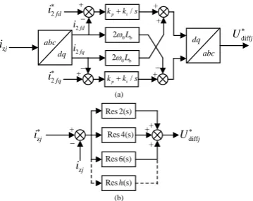
D. Circulating Current Control
At the beginning, average control with PI controllers is used to suppress the circulating current, and the average of inner currents in upper and lower arms as well as the mean value of the submodule voltages are calculated as return values [10]. However, the double-line-frequency negative sequence components of the circulating currents cannot be completely eliminated but suppressed to a small amplitude in [10]. Fig. 7 shows the control block of typical circulating current control methods mentioned above.
E. Voltage Balancing Control
A series of methods based on voltage balancing control to reduce the switch frequency are proposed, which can be approximately classified as following:
1) A slow-rate voltage balancing strategy [11], which make the capacitor voltage sorting operate with a rate slower than that in signal modulation, slowdowns the updating rate of the SMs index and reduces the switch frequency consequently.
2) A modified sorting method, compares the required number of SMs in current period with the number in previous period, and only extra SMs will be chosen to inserted or bypassed according the difference between the two numbers.
3) A modified voltage balancing method [12] adds constant voltage offsets multiplied with the switching states to the capacitor voltages before sorting, provides a fictitious separation between the voltages of the connected and bypassed SMs.
4) A model predictive control method introduces a weighting factor for switching state to lower the switching frequency. The SMs that have been switched on in previous sample period will get smaller cost function values and thus have a greater chance to be chosen in current period.
5) A grid-frequency-switched voltage balancing method [13] provides different drive pulse widths with the same phase angle in each switching period as a reference value to assign the produced pulses.
F. Operation under Different Fault Conditions
Various failures may occur during MMC operation, and the studies on failure handling can be simply divided based on the failure type as following:
1) Unbalanced gird conditions: the unbalanced grid conditions are the most common faults, and can be further divided into phase to phase fault and line to ground fault. Three phase variables are decoupled into positive and negative sequence subsystems, which can be controlled independently with respective reference signals. The reference signals are calculated based on the control objectives, which include keeping ac side currents balanced by eliminating negative sequence currents, keeping active power stable by adding proper negative sequence currents and suppressing circulating current under unbalanced conditions [15]. The analysis of different fault characteristics for a MMC-HVDC system under three possible single-line-to-ground fault conditions is proposed in [16] .
to a series connected double submodule (SDSM) and the capability to block the dc link fault current is realized without tripping ac circuit breaker. Chao Chen et al. present a control scheme that permits the MMC with HB-SM topology to exchange active and reactive powers through the ac grid when operating in boost and buck modes, that is to say, the DC faults can be traversed without a converter blocking [20]. Rong Zeng et al. propose a principle for a hybrid MMC which incorporates mixed FB-SM and HB-SM, taking both the advantages of the dc fault block capacity in FB-SM and the low switching devices requirement in HB-SM [21].
Figure 6. Multilevel carrier waveforms (a) phase disposition, (b) phase opposition disposition, (c) alternative phase opposition
disposition (d) saw-tooth carrier rotation, (e) phase shifted.
abc dq
/
pi
k k s
/
pi
k k s
0b
2L
0b
2L +
+
+
+
+
zj
i Udiffj
2fd
i
2fq
i
2fd
i
2fq
i
dq abc
+
zj
i
Res 2(s)
Res 4(s)
Res 6(s)
Res (s)h
diffj
U zj
i
(b) (a)
+
+ +
Figure 7. Typical circulating current suppressing controller: (a) CCSC, (b) circulating current resonant control
3) SM fault conditions: the techniques of failure diagnosis and fault devices location are significant in SM faults reactions. A detection approach for a FB-SM based MMC is proposed in [22], by analyzing the magnitude of the switching frequency component of the output phase
voltage the faulty cell can be determined, however, this method is powerless in locating specific faulty device. A Sliding Mode Observer (SMO) based fault detection method for an MMC is proposed in [23] which can not only locate the fault cell but also the fault switching device without extra sensors. Two open switch SM failure detection and location methods based on clustering algorithm and calculated capacitance respectively are proposed in [24], which can accurately detect and locate the fault SMs within a reasonable time without any additional sensor. Redundant SMs are put into operation instead of faulty cells when SM faults occur. Pengfei Hu et al. compare different design schemes of redundant SMs and indicate that the most economic and reliable scheme is making the redundant SMs in spinning reserve [25].
V. DESIGN AND ANALYSIS OF THE MMC APPLICATION SYSTEM
A. Parameter Selection
The system design works mainly focus on the parameter selection of SM capacitor and arm inductor for certain SM topology. The principle of SM capacitor design is put forward in [26], but only analysis of the SM voltage ripple is taken into account. Lucas Cunico presents the minimum SM capacitor requirement according to the load displacement angle, operating frequency and output power in [27]. The capacitor selection constraints based on four requirements, i.e. the maximum capacitor voltage, voltage ripple, ripple current and SM voltage capability are proposed in [28] respectively. Rong Zeng et al. in [29] propose a hybrid MMC with both HB-SM and FB-SM in each arm, and the variations for different SMs capacitor selection are deduced based on their interactive behavior.
On the aspect of arm inductor design, the design principle is elaborated in [26] based on suppressing the second order harmonic circulating current and avoiding resonance. Two distinctive functions of the arm inductor in MMC for suppressing the circulating current and limiting the fault current rise rate are described in [30]. Furthermore, the reduction of current ripple at the switching frequency is considered and related design principle is derived.
sorting methods provide significant enhancements in loss performance. It is also accepted that the circulation current suppressing control do enhance the effectiveness in reducing power loss but the effect is deemed not so significant [32].
Another way of power loss evaluation in MMC utilizes the analytical analysis and simplified models, which can simplify the calculation process and thus shorten the consumed time. But the shortage of this kind of method is that the accuracy of the calculating results can’t be guaranteed occasionally.
C. Reliability Analysis
The reliability analysis of MMC is closely relevant with the redundant level of SMs in MMC configuration. The converter reliability will be limited by control hardware at a certain redundancy level [30]. The reliability of the MMC increases with the redundant SM number growing, however, higher complexity in control system design and larger investments will also come along. The approach to calculate the optimal SM redundancy configuration of the hybrid MMCs is proposed. The lifetime prediction of MMC is proposed based on power cycling and thermal cycling, which is considered important for better understanding the improvement of the reliability of MMC.
VI. CONCLUSION
The MMC receives a widespread favor since it has been proposed due to its scalability and high performance in power transmission. The popularization of MMC will continuously promote the developments in renewable energy grid connecting and flexible HVDC system. MMC is under sustained improvement with further research, where follows new scientific issues and research directions.
The optimal redundancy configuration and hybrid strategy of multiple SM topologies is worth further study, which can comprehensively give free play to the diverse strengths of SMs in fault handling, output performance, efficiency and economic investment.
New semiconductor devices are developing and getting matured over the past few years, and they have good features such as low switching loss and high-speed switching capability when compared with traditional switching devices. However, high cost of new devices hinders the further applications in MMC currently. So it is a major concern that how to take advantages of the new devices economically by ways of substitutions and mixed use with traditional devices.
On the basis of above, improved structures of MMC will be put forward, and it is necessary to find new approaches of control strategies and modulation methods that are suitable for new structures or devices to exert their characteristic potential.
ACKNOWLEDGMENT
The authors would like to acknowledge the financing support of the National Natural Science Foundation of China (51377105).
REFERENCES
[1] M. Saeedifard and I. Reza, “Dynamic performance of a modular multilevel back-to-back HVDC system,” IEEE Trans. Power. Deliv., vol. 25, no. 4, pp. 2903-2912, 2010.
[2] M. Guan and X. Zheng, “Modeling and control of a modular multilevel converter-based HVDC system under unbalanced grid conditions,” IEEE Trans. Power. Electron., vol. 27, no. 12, pp. 4858-4867, 2012.
[3] X. Shi, et al., “Modelling, control design and analysis of a startup scheme for modular multilevel converters,” IEEE Trans. Ind. Electron., vol. 62, no. 11, pp. 7009-7024, 2015.
[4] J. Xu, et al., “New precharge and submodule capacitor voltage balancing topologies of modular multilevel converter for VSC-HVDC application,” in Proc. IEEE Asia-Pacific Power and Energy Engineering Conference, 2011.
[5] Y. Xue, Z. Xu, and G. Tang, “Self-start control with grouping sequentially precharge for the C-MMC-based HVDC system,”
IEEE Trans. Power. Deliv., vol. 29, no. 1, pp. 187-198, 2014. [6] B. Li, et al., “Closed-Loop precharge control of modular
multilevel converters during start-up processes,” IEEE Trans. Power. Electron., vol. 30, no. 2, pp. 524-531, 2015.
[7] T. Kai, et al., “A simple and cost-effective precharge method for modular multilevel converter by using a low-voltage DC source,”
IEEE Trans. Power. Electron., vol. 30, no. 2, pp. 524-531, 2015. [8] J. W. Moon, et al., “Model predictive control with a reduced
number of considered states in a modular multilevel converter for HVDC system,” IEEE Trans. Power. Deliv., vol. 30, no. 2, pp. 608-617, 2015.
[9] S. Rohner, et al., “Modulation, losses, and semiconductor requirements of modular multilevel converters,” IEEE Trans. Ind. Electron., vol. 57, no. 9, pp. 2633-2642, 2010.
[10] M. Hagiwara and H. Akagi, “PWM control and experiment of modular multilevel converters,” in Proc. IEEE Power Electronics Specialists Conference, 15-19 June 2008, pp. 154-161.
[11] J. Qin and M. Saeedifard, “Reduced switching-frequency voltage-balancing strategies for modular multilevel HVDC converters,”
IEEE Trans. Power. Deliv., vol. 28, no. 4, pp. 2403-2410, 2013. [12] R. Darus, et al., “A modified voltage balancing algorithm for the
modular multilevel converter, evaluation for staircase and phase-disposition PWM,” IEEE Trans. Power. Electron., vol. 30, no. 8, pp. 4119-4127, 2015.
[13] F. Deng and Z. Chen, “Voltage-Balancing method for modular multilevel converters switched at grid frequency,” IEEE Trans. Ind. Electron., vol. 62, no. 5, pp. 2835-2847, 2015.
[14] H. Saad, et al., “MMC capacitor voltage decoupling and balancing controls,” IEEE Trans. Power. Deliv., vol. 30, no. 2, pp. 704-712, 2015.
[15] Y. Zhou, et al., “Analysis and control of modular multilevel converters under unbalanced conditions,” IEEE Trans. Power. Deliv., vol. 28, no. 4, pp. 1986-1995, 2013.
[16] X. Shi et al., “Characteristic investigation and control of a modular multilevel converter-based HVDC system under single-line-to-ground fault conditions,” IEEE Trans. Power. Electron., vol. 30, no. 1, pp. 408-421, 2015.
[17] G. Tang, X. Xu, and Y. Zhou, “Impacts of three MMC-HVDC configurations on AC system stability under DC line faults,” IEEE Trans. Power. Syst., vol. 29, no. 6, pp. 3030-3040, 2014.
[18] Y. Xue and Z. Xu, “On the bipolar MMC-HVDC topology suitable for bulk power overhead line transmission, configuration, control, and DC fault analysis,” IEEE Trans. Power. Deliv., vol. 29, no. 6, pp. 2420-2429, 2014.
[19] J. Zhang and C. Zhao, “The research of SM topology with DC fault tolerance in MMC-HVDC,” IEEE Trans. Power. Deliv., vol. 30, no. 3, pp. 1561-1568, 2015.
[20] C. Chen, et al., “H-bridge modular multi-level converter, control strategy for improved DC fault ride-through capability without converter blocking,” IET Power Electronics, vol. 8, no. 10, pp. 1996-2008, 2015.
[21] R. Zeng, et al., “Pre-charging and DC fault ride-through of hybrid MMC based HVDC systems,” IEEE Trans. Power. Deliv., vol. 30, no. 3, pp. 1298-1306, 2015.
[22] P. Lezana, R. Aguilera, and J. Rodríguez, “Fault detection on multicell converter based on output voltage frequency analysis,”
[23] S. Shao, et al., “Fault detection for modular multilevel converters based on sliding mode observer,” IEEE Trans. Power. Electron., vol. 28, no. 11, pp. 4867-4872, 2013.
[24] Q. Yang, J. Qin, and M. Saeedifard, “SubModule failure detection methods for the modular multilevel converter,” in Proc. IEEE Energy Conversion Congress and Exposition, 2015.
[25] P. Hu, et al., “Energy-balancing control strategy for modular multilevel converters under submodule fault conditions,” IEEE Trans. Power. Electron., vol. 29, no. 9, pp. 5021-5030, 2014. [26] Z. Sun, et al., “Parameter design principle of the capacitors and
inductors in the power electronic transformer based on MMC,” in
Proc. 17th International Conference on Electrical Machines and Systems, 2014.
[27] L. M. Cunico, et al.,“Parameters design for Modular Multilevel Converter (MMC),” in Proc. IEEE Brazilian Power Electronics Conference, 2013.
[28] Y. Tang, et al., “Capacitor selection for modular multilevel converter,” in Proc. IEEE Energy Conversion Congress and Exposition, 2014.
[29] R. Zeng, et al., “Design and operation of a hybrid modular multilevel converter,” IEEE Trans. Power. Electron., vol. 30, no. 3, pp. 1137-1146, 2015.
[30] Q. Tu, et al., “Parameter design principle of the arm inductor in modular multilevel converter based HVDC,” in Proc. IEEE International Conference on Power System Technology, 2010. [31] L. Wu, et al., “Efficiency evaluation of the modular multilevel
converter based on Si and SiC switching devices for medium/high-voltage applications,” IEEE Trans Electron. Devic., vol. 62, no. 2, pp. 286-293, 2015.
[32] J. Li, et al., “Loss calculation method and loss characteristic analysis of MMC based VSC-HVDC system,” in Proc. IEEE International Symposium on Industrial Electronics, 2013. [33] Q. Tu and Z. Xu, “Power losses evaluation for modular multilevel
converter with junction temperature feedback,” in Proc. IEEE Power and Energy Society General Meeting, 2011.
[34] F. Erturk and A. M. Hava, “A detailed power loss analysis of modular multilevel converter,” in Proc. IEEE Applied Power Electronics Conference and Exposition, 2015.
Huancheng Lin was born in Zhejiang, China, in June 1991. He received the B.S. degree in electrical engineering from Zhejiang University, Hangzhou, China, in 2013. He is currently pursuing the Ph.D. degree in electrical engineering at Shanghai Jiao Tong University, Shanghai, China. His research interests include power electronics and its applications in VSC-HVDC and motor control.