R E S E A R C H
Open Access
Guide star based deconvolution for
imaging behind turbid media
Jale Schneider and Christof M Aegerter
*Abstract
Background:If structures of interest are hidden beneath turbid layers such as biological tissues, imaging becomes challenging, even impossible. However, if the point spread function of the system is known from the presence of a guide star, application of common deconvolution algorithms can be a convenient approach to reconstruct even heavily scrambled images. In this work, we present the severity of scattering and the capability of deconvolution techniques in optical settings realistically mimicking biological applications.
Methods:We determine the point spread function (PSF) of the optical path using a single fluorescent bead hidden
behind a scattering layer. Once the PSF is obtained, a scene containing several beads is brought to the exact the same position behind the scattering layer. The scrambled image of the scene is then deconvoluted with the PSF. Plastic films and thin slices of chicken tissues are used as scattering layers.
Results:Despite the low signal provided by small fluorescent particles and their short distance of a few millimeters to the turbid media, the reconstructed images reproduced the original scenes successfully. The spatial variance of the PSF caused by the inhomogeneous scattering layer mainly limited the size of the reconstructed area.
Conclusion:Our method overcomes the negative effects of scattering on the detection side of an imaging system. However, it can be combined with wavefront shaping methods optimizing the illumination path as well leading to even further increase of signal to noise ratio and image quality. The required guide star can be brought inside the biological sample to a desired position using optical fibers as a light guide or using capillaries filled with bright fluorescent molecules.
Keywords:Deconvolution, Blind deconvolution, Imaging behind turbid media, Scattering
Background
Most optical imaging systems suffer from sample in-duced, as well as system induced aberrations and scatter-ing. Hence, great efforts in terms of adaptive optics and digital image processing have been made in order to cor-rect imperfections within the optical path and to restore the original scene from the acquired image.
Traditional adaptive optics techniques in fluorescence microscopy rely on direct wavefront measurements, employing e.g. a Hartmann-Shack sensor [1–3]. This sensor detects and analyses either the aberrant wavefront of the backscattered excitation light [4, 5] or the wavefront of a fluorescent guide star [6–8]. The compensation of the aber-rations is then performed by a spatial light modulator or a deformable mirror device. These techniques can achieve
correction speeds on the sub-second time scale if the guide star is bright enough. However, direct wavefront sensing with conventional sensors requires ballistic photons. Thus, they cannot be employed in the case of multiple scattering, which leads to the complete loss of phase information.
Alternatively, iterative wavefront shaping methods can be used to create a certain image metric such as max-imum brightness or maxmax-imum sharpness [9–11]. These methods require only wavefront shaping devices making the overall system cheaper and less complicated. But achieving the desired optimum involves capturing of large number of frames or necessitates dedicated tech-niques working with less number of iterations [12–14].
Also, Fresnel guide star based approaches can correct aberrations on the illumination path as well as the detec-tion path [15,16].
An easier approach in case of severe scattering is directly to apply deconvolution within the range of the optical * Correspondence:[email protected]
Physics Institute, University of Zurich, Winterthurerstrasse 190, 8057 Zurich, Switzerland
memory effect as stated in the work of Edrei et al. [17]. Memory effect describes wavefront correlation valid within a certain angular range [18]. Even though speckle patterns behind a turbid medium look random, they are highly cor-related if the incoming light hits the scattering layer by only a slightly different angle. The area at image plane which can be scanned without losing the speckle correlation dic-tates the region where deconvolution would perform well despite scattering. In general, deconvolution operations [19–21] aim to remove or reverse the effects of blurring, noise and scattering in microscopy images. It is one of the key image processing tools enhancing the contrast of 3-D image stacks of confocal and widefield microscopes. Decon-volution enables a more accurate quantitative data analysis, increases the signal to noise ratio and restores fine details [22–24]. Common algorithms require the knowledge of, or at least a good estimation of the system’s response to a sin-gle point source –i.e. the point spread function (PSF). A final image containing the signal of many fluorescence emitters mathematically corresponds to the convolution of the original scene with the PSF, which allows the applica-tion of the inverse deconvoluapplica-tion operaapplica-tion.
In this paper, we present how we traced back the fluorescence signal behind scattering media by applying deconvolution schemes. The main difference compared to the work of Edrei et al. is the optical setup which mimics a realistic biological scene. Biologists mostly apply elaborate techniques like clearing or slicing during sample preparation to minimize image degradation due to scattering. We saw in the work of Edrei et al. a great potential for image restoration of biological turbid sam-ples which might reduce the sample preparation steps and even enable in vivo imaging. Instead of direct laser illumination, we employed small fluorescent particles as
a signal source providing far less signal. We also reduced the distance between the signal source and the scattering layer from several centimeters down to a few millimeters resulting in a reduced area in the image field where the memory effect holds. The determination of the PSF, based on the guide star approach still has led to success-ful reconstruction as shown below.
Methods
Optical setup and the measurement procedure
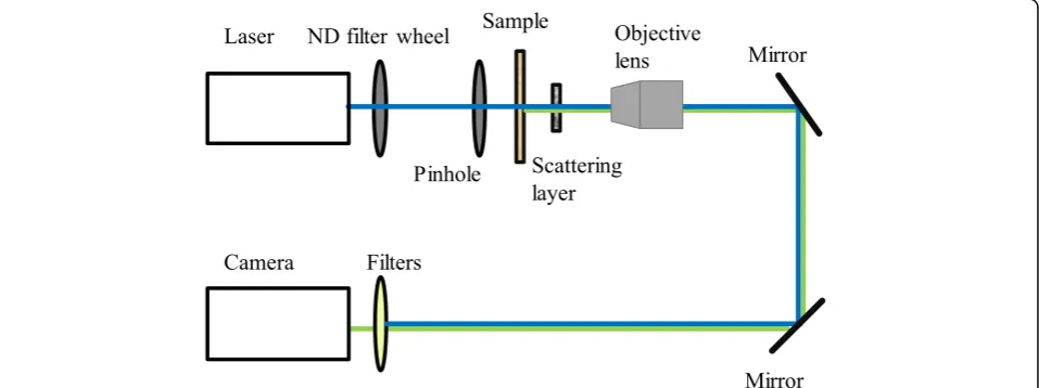
Our samples consisted of 4μm yellow-green fluorescent beads (Invitrogen FluoSpheres®, USA). The beads were diluted 1:5000 in distilled water and squeezed between a coverslip and a glass slide as a thin film embedded in water. The arrangement was then mounted on a manual translation stage (MS1S, Thorlabs Inc., USA) for three axis translation. A cyan laser (488 nm, Spectra-Physics, USA) illuminated the sample after passing a 20μm pin-hole (Thorlabs Inc., USA). A neutral density filter wheel (Thorlabs Inc., USA) allowed the adjustment of the laser power. The power applied to the beads was a few tens of microwatts without the scattering layer and up to 2 milliwatt with the scattering layer. An objective lens with long working distance of 5.2 mm (Zeiss Plan-Neofluar, 10×/0.3) collected the fluorescence signal and imaged the beads directly onto the camera (ORCA-Flash 4.0 LT, Hamamatsu, Japan). We employed no other lenses than the objective lens. The magnification was 20× (calculated as image distance divided by the object distance) as given by the classical lens equation. The typical camera exposure times were set to 30 ms for imaging without the scattering layer and 300 ms to 1 s in the presence of the scattering layer (see also Fig.1. for the schematic of the setup). A bandpass filter (FF01–525/45, Semrock
Fig. 1The experimental setup. ND filter: neutral density filter. The blue line represents the excitation light; the green line represents the fluorescence emission. The scattered fluorescence signal is directly imaged onto the camera via objective lens. The magnification is given as the image distance divided by the object distance. The filters in front of the camera transmit the fluorescence and block the laser light
Inc., USA) and a notch filter (NF488–15, Thorlabs Inc., USA) were placed in front of the camera to eliminate laser light and ambient light.
First, we determined a location within the sample with only a single illuminated bead to be used as a guide star. Second, we determined another location with several beads serving as a more complicated fluorescent scene. Finally, we placed a scattering layer between the sample and detection objective. Both locations within the sam-ple are then brought to the exact same position in front of the scattering layer one after another. As expected, the scattering layer scrambled the fluorescence signals from the guide star, as well as from the scene, heavily. We used the scattered fluorescent image of the guide star as the point spread function (PSF). We then decon-voluted the scrambled image of the scene using this PSF. Deconvolution operations were performed with Matlab® R2015a (The MathWorks Inc., USA) using the built-in functions [25–27] and with the ImageJ Deconvo-lutionLab Plugin (Biomedical Imaging Group, EPFL, Switzerland, [28]). We applied Richardson-Lucy algo-rithms as well as blind deconvolution.
Results
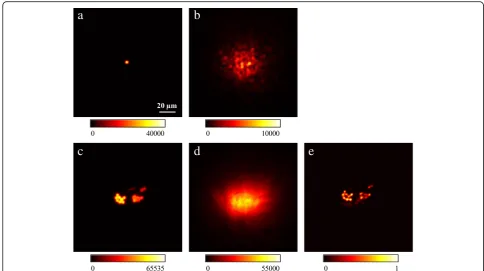
Plastic film as a scattering layer
We started our experiments with a piece of plastic bag of a thickness of 75 μm as a technical scattering layer. To determine the scattering properties of the plastic film; we measured the total reflectance, total transmit-tance and the collimated transmittransmit-tance of the scattering layer as suggested by Prahl et al. [29, 30]. We inputted the measured values into his open access “inverse adding-doubling program” [31]. A detailed explanation of the characterization of our technical layer is provided in the Additional file 1. We found the scattering mean free path on different positions in the plastic film to be in the range of 40 μm to 70 μm. The anisotropy factor (average cosine of the scattering angle) varied from 0.94 to 0.99 indicating strong forward scattering. The scatter-ing mean free paths of many biological tissues vary be-tween 30 μm to 300μm by anisotropy factors of 0.8 to 0.98 [32]. Thus, our technical layer suitably mimicked a thin slice of biological tissue.
We took images of our guide star and another fluores-cent scene behind the plastic film with the procedure
a
b
c
d
e
explained in the previous chapter. Exemplary sets of re-sults are shown in Figs.2and3.
Chicken tissue as a scattering layer
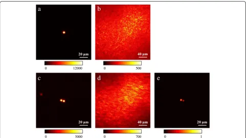
After these encouraging outcomes with a technical scatter-ing layer, we moved on to include a biological tissue as the turbid medium. Also in this case, the reconstruction of the original scenes succeeded, as depicted in Figs.4and5. The thicknesses of the chicken tissues were approximately 100 μm and 300 μm respectively. Figure 5 demonstrates the dependence of the deconvolution success on the mem-ory effect range. Structures within 25μm around the center were reconstructed whereas information from the particles further away got lost. On samples thicker than 300μm, the fluorescence signal reaching the camera dropped to the noise level hindering the evaluation of our technique.
Discussion
The determination of the PSF of a scattering layer using a guide star has led to successful reconstruction of dras-tically degraded fluorescent scenes as long as the signal to noise ratio was sufficient. The incoherent nature of the fluorescence allowed a straight-forward deconvolu-tion because the intensity distribudeconvolu-tion of the camera
image consisted of the superposition of the intensity dis-tributions of adjacent points in the image field. In case of coherence light sources, characterization of the inter-ference effects would have been required.
We recorded the PSF of the optical path using fluores-cent particles of 4μm diameter to achieve a sufficient sig-nal to noise ratio at the image plane despite scattering. Strictly speaking, these rather big particles cannot be con-sidered as a point source. If smaller particles were behind the scattering layer, deconvolution of their image with the PSF recorded by these big particles would have produced artefacts. Smearing effects depending on the number of the iterations would have occurred. Therefore, the decon-volution operations shown here perform reliably for re-construction of objects with a size of > 4μm.
The main bottleneck of this technique is the spatial vari-ance of the PSF as given in every type of guide star based method. The range of spatially invariance PSF determines the size of the reconstructed area and is directly related to the memory effect range. However, compared to isotropic-ally scattering media, the anisotropicisotropic-ally forward scatter-ing biological tissues predict an extended range of the memory effect [33] where the PSF is still valid making this technique suitable for imaging in biology.
a
b
c
d
e
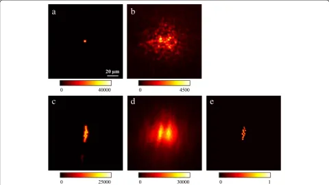
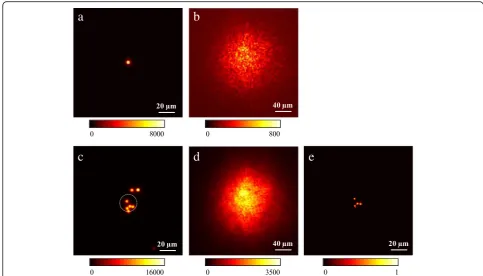
Fig. 3Another data set acquired with a plastic bag as turbid medium placed 5 mm in front of the fluorescent sample.aThe image of a single fluorescent bead used as guide star.bThe same scene as in (a) scrambled by the scattering layer used as PSF of the system.cThe image of a fluorescent scene.dThe same scene as in (c) scrambled after passing the same part of the turbid medium.eReconstruction of the fluorescent scene seen in (c): Image (d) is deconvoluted with image (b) using Richardson-Lucy deconvolution with 120 iterations. All images are contrast-adjusted for better visibility as can be seen on individual colormap scales
The required guide star can be brought inside the bio-logical sample to a desired position using optical fibers as a light guide or using capillaries filled with bright fluorescent molecules. If no artificial structures are de-sired at all, one can fluorescently label a structure of the specimen as well. However, such a labeling via expres-sion of fluorescent proteins or utilizing antibodies might not provide enough signal.
Edrei et al. used either a diffuser (negligible thickness of scattering layer but completely isotropic scattering) or 1 mm scotch tape as turbid medium. Both turbid layers used in his study would cause more severe scattering than our chicken tissues. Since the fluorescence signal is very weak compared to direct laser light as used by his work, the signal to noise ratio at the camera would drop quickly on such high degrees of scattering. Here, the main limiting component from the technical side is the objective lens with the limited numerical aperture. The higher the scat-tering (due to high scatscat-tering coefficient and/or the thick-ness of the scattering layer) the bigger is the angular area the photons leave the scattering layer and the higher is the number of photons which cannot be collected by the ob-jective lens. As stated in the Methods Section, we employed an air objective lens with long working distance of 5.2 mm in our setup with a moderate numerical
aperture of 0.3. This objective lens allowed us to insert and evaluate different scattering layers easily. For further studies, an objective lens with higher numerical aperture with appropriate embedding medium is recommended to collect scattered photons from higher angles (e. g. glycerol objectives with numerical aperture up to 1.3). This would increase the penetration depth as well which has been 300μm in our study so far. Besides, one should note that the anisotropic scattering in biological samples is more beneficial compared to the isotropic scattering in technical samples in terms of signal collection.
If the guide star is bright and stable enough, i.e. if the size of light emitting particle is big enough and still not disturbing the physiology of the sample, some in vivo applications can be performed as well. For this purpose, the guide star image and image of the scene in its close vicinity can be captured continuously with the camera with short exposure times in tens of milliseconds range. Image data at video rate can be handled and processed online or offline with a dedicated computer. A big chal-lenge of such an application would be the differentiation of the signals coming from the guide star and the struc-tures of interest. The guide star can be labeled with a slightly different color and a synchronized filter wheel in front of the camera can enable the differentiation of the
a
b
c
d
e
images. Since the scattering properties depend on the wavelength, the labeling of the guide star and the bio-logical structure must be as similar as possible. Another possibility could be to label the structures of interest with switchable fluorophores which can be turned on and off depending on the wavelength and timing of the excitation laser. However, if the in vivo dynamics change the scattering properties within a few milliseconds or faster, this technique would most probably suffer from low signal. Additionally, fast transfer of image data would be challenging.
In most experiments, Richardson-Lucy as well as blind deconvolution algorithms could reconstruct - at least the outlines of the original scene - similarly well. Richardson-Lucy algorithms produced increasingly nega-tive values from the image corners towards the center with more iterations. In the corresponding figures above, these negative values were set to zero.
The inverse adding-doubling method used to characterize the technical scattering layer assumes condi-tions like homogenous optical properties and infinite slab geometry. These conditions were not fully satisfied. How-ever, our samples had an area several times bigger than the illumination spot avoiding any edge effects. Movement
of the scattering layer within a few millimeters resulted in a variation of less than 10% of measured values. The vari-ation became bigger by displacements exceeding 5 mm. Therefore, we mentioned the mean free path and the an-isotropy factor of the sample not as absolute values but as a range as mentioned in the Results Section.
Conclusion
The structures of interest in biological tissues are covered with scattering layers both on the illumination path and detection path. Also, a camera cannot be placed behind the tissue making a backscattering setup necessary. This paper primarily presents a method to overcome the scattering on the detection side but it also includes a convenient combination possibility with wavefront shaping techniques optimizing the illumination path. Many of wavefront shaping methods make use of a feedback signal coming from behind the scattering layer [34–42]. The guide star required in this work can be used as such a feedback signal source for the optimization on the illumination path as well. For example, the overall increase of fluorescence signal at a certain point within the ROI can be used as a metric for the illumination optimization resulting in an ad-equately excited small fluorescent structure. The scrambled
a
b
c
d
e
Fig. 5A data set acquired with a chicken tissue with a thickness of about 300μm as turbid medium placed 1 mm in front of the fluorescent sample. (a) The image of a single fluorescent bead used as guide star. (b) The same scene as in (a) scrambled by the scattering layer used as PSF of the system. (c) The image of a fluorescent scene. (d) The same scene as in (c) scrambled after passing the same part of the turbid medium. (e) Reconstruction of the fluorescent scene seen in (c): Image (d) is deconvoluted with image (b) using Richardson-Lucy deconvolution with 150 iterations. The reconstruction succeeded over a field of approximately 25μm as marked in (c) with a white circle. All images are contrast-adjusted for better visibility as can be seen on individual colormap scales
image of this structure can then be used as the PSF of the detection path. If the wavefront is optimized to create a single focus, it can be scanned within the same memory range valid for the deconvolution area as well. Instead of fluorescent particles, also an optical fiber as a light guide can be brought into the sample.
Besides a backscattering setup, a light sheet micro-scope would benefit from our approach to a great extent. Here, the illumination and imaging paths are decoupled allowing every type of improvement on the excitation side. Deconvolution can then be applied on the detec-tion side independently. Bourgenot et al. has already showed the power of adaptive optics for the imaging arm of a light sheet microscope which could have been applied on the illumination arm as well [43].
Our method can be combined not only with the already mentioned methods but also with techniques based on optical phase conjugation [44,45]. Optical phase conjuga-tion proved to be a powerful tool for focusing light through tissues of thicknesses up to 10 cm [46] and is also capable for high speed applications [47]. Optical phase conjugation of fluorescence signal behind turbid media have been showed as well [48]. Complementing these techniques with deconvolution schemes would lead to an overall advance in the imaging of biological samples.
Additional file
Additional file 1:Characterization of the plastic film as scattering layer. (DOCX 55 kb)
Abbreviations
PSF:Point spread function; ND filter: Neutral density filter
Acknowledgements
We thank Nicholas LeBow for his preliminary work investigating deconvolution parameters.
Funding
This work was funded by the Swiss National Science Foundation.
Availability of data and materials
The data supporting the conclusions of this article are included within the present article.
Authors’contributions
CMA and JS designed the studies. JS built the setup and conducted the experiments. Both authors analyzed the data and wrote the manuscript. Both authors read and approved the final manuscript.
Competing interests
The authors declare that they have no competing interests.
Publisher’s Note
Springer Nature remains neutral with regard to jurisdictional claims in published maps and institutional affiliations.
Received: 1 June 2018 Accepted: 24 September 2018
References
1. Booth, M.J.: Adaptive optics in microscopy. Philos. Trans. R. Soc. A Math. Phys. Eng. Sci.365, 2829 (2007)
2. Ji, N.: Adaptive optical fluorescence microscopy. Nat Meth.14, 374–380 (2017)
3. Kubby, JA (ed.): Adaptive optics for biological imaging. CRC Press (2013) 4. Rahman, S.A., Booth, M.J.: Direct wavefront sensing in adaptive optical
microscopy using backscattered light. Appl. Opt.52, 5523–5532 (2013) 5. Rueckel, M., Mack-Bucher, J.A., Denk, W.: Adaptive wavefront correction in
two-photon microscopy using coherence-gated wavefront sensing. Proc. Natl. Acad. Sci.103, 17137–17142 (2006)
6. Tao, X., Fernandez, B., Azucena, O., Fu, M., Garcia, D., Zuo, Y., Chen, D.C., Kubby, J.: Adaptive optics confocal microscopy using direct wavefront sensing. Opt. Lett.36, 1062–1064 (2011)
7. Wilding, D., Pozzi, P., Soloviev, O., Vdovin, G., Verhaegen, M.: Adaptive illumination based on direct wavefront sensing in a light-sheet fluorescence microscope. Opt. Express.24, 24896–24906 (2016)
8. Wang, K., Sun, W., Richie, C.T., Harvey, B.K., Betzig, E., Ji, N.: Direct wavefront sensing for high-resolution in vivo imaging in scattering tissue. Nat. Commun.6(7276), (2015)
9. Albert, O., Sherman, L., Mourou, G., Norris, T.B., Vdovin, G.: Smart microscope: an adaptive optics learning system for aberration correction in multiphoton confocal microscopy. Opt. Lett.25, 52–54 (2000)
10. Galwaduge, P.T., Kim, S.H., Grosberg, L.E., Hillman, E.M.C.: Simple wavefront correction framework for two-photon microscopy of in-vivo brain. Biomedical Optics Express.6, 2997–3013 (2015)
11. Wright, A.J., Burns, D., Patterson, B.A., Poland, S.P., Valentine, G.J., Girkin, J.M.: Exploration of the optimisation algorithms used in the implementation of adaptive optics in confocal and multiphoton microscopy. Microsc. Res. Tech.
67, 36–44 (2005)
12. Booth, M.J.: Wave front sensor-less adaptive optics: a model-based approach using sphere packings. Opt. Express.14, 1339–1352 (2006)
13. Booth, M.J.: Wavefront sensorless adaptive optics for large aberrations. Opt. Lett.32, 5–7 (2007)
14. Débarre, D., Botcherby, E.J., Watanabe, T., Srinivas, S., Booth, M.J., Wilson, T.: Image-based adaptive optics for two-photon microscopy. Opt. Lett.34, 2495–2497 (2009)
15. Koukourakis, N., Fregin, B., König, J., Büttner, L., Czarske, J.W.: Wavefront shaping for imaging-based flow velocity measurements through distortions using a Fresnel guide star. Opt. Express.24, 22074–22087 (2016)
16. Radner, H., Büttner, L., Czarske, J.: Interferometric velocity measurements through a fluctuating phase boundary using two Fresnel guide stars. Opt. Lett.40, 3766–3769 (2015)
17. Edrei, E., Scarcelli, G.: Memory-effect based deconvolution microscopy for super-resolution imaging through scattering media. Sci. Rep.6(33558), (2016) 18. Bertolotti, J.: Multiple scattering: Unravelling the tangle. Nat. Phys.11, 622–
623 (2015)
19. Jansson, PA (ed.): Deconvolution of images and spectra (2nd ed.). Academic Press, Inc. (1996)
20. Biggs, DSC: 3D Deconvolution microscopy. In: Current Protocols in Cytometry, 52. John Wiley & Sons, Inc. (2001)
21. Starck, J.L., Pantin, E., Murtagh, F.: Deconvolution in astronomy: a review. Publ. Astron. Soc. Pac.114, 1051–1069 (2002)
22. Sibarita, J.B.: Deconvolution Microscopy. Adv. Biochem. Eng. Biotechnol.95, 201–243 (2005)
23. McNally, J.G., Karpova, T., Cooper, J., Conchello, J.A.: Three-dimensional imaging by Deconvolution microscopy. Methods.19, 373–385 (1999) 24. Sarder, P., Nehorai, A.: Deconvolution methods for 3-D fluorescence
microscopy images. IEEE Signal Process. Mag.23, 32–45 (2006) 25. Biggs, D.S.C., Andrews, M.: Acceleration of iterative image restoration
algorithms. Appl. Opt.36, 1766–1775 (1997)
26. Richardson, W.H.: Bayesian-based iterative method of image restoration. J. Opt. Soc. Am.62, 55–59 (1972)
27. Lucy, L.B.: An iterative technique for the rectification of observed distributions. Astron. J.79, 745 (1974)
29. Prahl, SA: Everything I think you should know about Inverse Adding-Doubling. Oregon Medical Laser Center.https://omlc.org/software/iad/ manual.pdf(2011). Accessed 01 March 2018
30. Prahl, S.A., van Gemert, M.J.C., Welch, A.J.: Determining the optical properties of turbid media by using the adding–doubling method. Appl. Opt.32, 559–568 (1993)
31. Prahl, SA: Inverse Adding-Doubling. Oregon Medical Laser Center.https:// omlc.org/software/iad/index.html(2017). Accessed 01 March 2018 32. Cheong, W.F., Prahl, S.A., Welch, A.J.: A review of the optical properties of
biological tissues. IEEE J. Quantum Electron.26, 2166–2185 (1990) 33. Schott, S., Bertolotti, J., Léger, J.-F., Bourdieu, L., Gigan, S.: Characterization of
the angular memory effect of scattered light in biological tissues. Opt. Express.23, 13505–13516 (2015)
34. Vellekoop, I.M.: Feedback-based wavefront shaping. Opt. Express.23, 12189–12206 (2015)
35. Mosk, A.P., Lagendijk, A., Lerosey, G., Fink, M.: Controlling waves in space and time for imaging and focusing in complex media. Nat Photon.6, 283–292 (2012)
36. Vellekoop, I.M., Mosk, A.P.: Focusing coherent light through opaque strongly scattering media. Opt. Lett.32, 2309–2311 (2007)
37. Vellekoop, I.M., Aegerter, C.M.: Scattered light fluorescence microscopy: imaging through turbid layers. Opt. Lett.35, 1245–1247 (2010) 38. Vellekoop, I.M., Aegerter, C.M.: Focusing light through living tissue. Proc.
SPIE.7554, 755430 (2010)
39. Ghielmetti, G., Aegerter, C.M.: Direct imaging of fluorescent structures behind turbid layers. Opt. Express.22, 1981–1989 (2014)
40. Ghielmetti, G., Aegerter, C.M.: Scattered light fluorescence microscopy in three dimensions. Opt. Express.20, 3744–3752 (2012)
41. Schneider, J., Aegerter, C.M.: Dynamic light sheet generation and fluorescence imaging behind turbid media. Journal of the European Optical Society-Rapid Publications.14(7), (2018)
42. Horstmeyer, R., Ruan, H., Yang, C.: Guidestar-assisted wavefront-shaping methods for focusing light into biological tissue. Nat Photon.9, 563–571 (2015)
43. Bourgenot, C., Saunter, C.D., Taylor, J.M., Girkin, J.M., Love, G.D.: 3D adaptive optics in a light sheet microscope. Opt. Express.20, 13252–13261 (2012) 44. Cui, M., McDowell, E.J., Yang, C.: An in vivo study of turbidity suppression by
optical phase conjugation (TSOPC) on rabbit ear. Opt. Express.18, 25–30 (2010)
45. Yaqoob, Z., Psaltis, D., Feld, M.S., Yang, C.: Optical phase conjugation for turbidity suppression in biological samples. Nat Photon.2, 110–115 (2008) 46. Shen, Y., Liu, Y., Ma, C., Wang, L.V.: Focusing light through biological tissue
and tissue-mimicking phantoms up to 9.6 cm in thickness with digital optical phase conjugation. J. Biomed. Opt.21, 085001 (2016)
47. Wang, D., Zhou, E.H., Brake, J., Ruan, H., Jang, M., Yang, C.: Focusing through dynamic tissue with millisecond digital optical phase conjugation. Optica.2, 728–735 (2015)
48. Vellekoop, I.M., Cui, M., Yang, C.: Digital optical phase conjugation of fluorescence in turbid tissue. Appl. Phys. Lett.101, 081108 (2012)