Vol. 04, Issue 04 (April. 2014), ||V2|| PP 01-07
Automation of Maximum Load Control using
8051-Microcontroller
Mr. B. T. Ramakrishna Rao, Anand Daga, K.V.V.Srinivasa Rao,
M.NaveenKumar, B.Ajay Kumar.
* Associate Professor, EEE- Dept., Lendi Institute of Engineering and Technology, Vizianagaram, Andhra Pradesh
** UG Students, EEE Dept., Lendi Institute of Engineering and Technology, Vizianagaram, Andhra Pradesh
Abstract : -It is from past few decades that the maximum demand for different types of consumers are being controlled manually in different forms, but in this project we would like to propose the control of maximum demand without involvement of human activity i.e., by using a controller. The controller used in this case can be of different types and can belong to any type of family. In this paper, we employ 8051 controller. The load demand at every instant is calculated and is compared with the permissible maximum load demand value, and when the instantaneous maximum demand value is inferior than the permissible limit then the operation is considered to be in equilibrium state, but when the value of instantaneous maximum demand crosses the limits of permissible maximum load demand then the controller comes into picture and controls(trips) the load by the phenomena of load shedding based on the priority set by the user.
I. INTRODUCTION
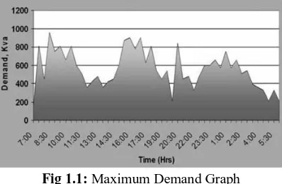
1.1. Maximum Demand: It is the greatest demand of the load on the Power station during a given period. The load on the power station varies from time to time. The maximum of all the demands that have occurred during a given period is the maximum demand.
Fig 1.1: Maximum Demand Graph
1.2. Effects of uncontrolled Maximum demand: 1.Unscheduled increase of demand on power system which effects the whole power system. 2. Heavy fine being imposed on the consumer when the maximum load demand value crosses the specified limit. 3. Possibility of unwanted power transmission and unwanted utilization.
1.3. How can we control Maximum demand: The purpose of controlling the demand is, not to exceed the contracted maximum demand limit. One way to do this is to shed non-critical loads...
Possible loads to be disconnected: Lights, Compressors, Air conditioners, Pumps, Fans and extractors, Packaging machinery, Shredders, Others... Generally, all those machine which do not affect the main production process or which are not essential.
II. IMPORTANT DEFINITIONS
1.1 Types of Demand:
2.1.1. Maximum Demand: It is the greatest demand of the load on the Power station during a given period. The load on the power station varies from time to time. The maximum of all the demands that have occurred during a given period is the maximum demand.
Automation of Maximum Load Control using 8051-Microcontroller
2.1.3. Average Load: The average of loads occurring on power station in a given period is known as average load or average demand.
2.1.4. Connected Load: It is the sum of continuous ratings of all the equipments connected to supply system. The sum of connected loads of all the consumers is the connected load to the power station.
2.1.5. Demand Factor: It is the ratio of Maximum demand on the power station to its connected load.
2.1.6. Load Factor: The ratio of average load to the maximum demand during a given period is known as load factor
2.1.7. Diversity Factor: The ratio of the sum of individual maximum demands to the maximum demand on power station is known as diversity factor.
2.1.8. Plant Capacity Factor: It is the ratio of actual energy produced to the maximum possible energy that could have been produced during a given period.
III. COMPONENTS DESCRIPTION
3.1. Energy Meter: An electricity meter or energy meter is a device that measures the amount of electrical energy consumed by a residence, business or an electrically powered device.
Fig 3.1: Energy Meter
3.2. Bridge Rectifier: A diode bridge is an arrangement of four (or more) diodes in a bridge circuit configuration that provides the same polarity of output for either polarity of input.
Fig 3.2: Bridge Rectifier
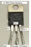
3.3. 7805-Voltage regulator: 7805 Voltage Regulator is a electronic circuit used for regulating voltage upto 5v DC
3.4. Blinking Reader (Light Dependent Resistor): A photoresistor LDR or photocell is a light-controlled variable resistor. The resistance of a photoresistor decreases with increasing incident light intensity; in other words, it exhibits photoconductivity.
Fig 3.4: Light Dependent Resistor
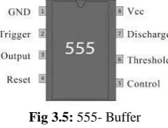
3.5. Buffer: A buffer is one that provides electrical impedance transformation from one circuit to another.
Fig 3.5: 555- Buffer
3.6. Micro Controller: Microcontroller (sometimes abbreviated µC, uC or MCU) is a small computer on single integrated circuit containing a processor core, memory, and programmable input/output peripherals. It also includes RAM chip in it. It can be used for controlling the process being carried out.
3.6.1 Oscillator: A crystal oscillator is an electronic oscillator circuit that uses the mechanical resonance of a vibrating crystal of piezoelectric material to create an electrical signal with a very precise frequency. This frequency is commonly used to keep track of time (as in quartz wristwatches), to provide a stable clock signal for digital integrated circuits, and to stabilize frequencies for radio transmitters and receivers.
Fig 3.6: AT89S52-MicroController Fig 3.6.1: Crystal Oscillator
3.7. Alarm Circuit/Buzzer: An alarm circuit gives an audible or other form of alarm signal about a problem or condition. Alarm circuit is outfitted with a siren.
Fig 3.7: Alarm Circuit/Buzzer
Automation of Maximum Load Control using 8051-Microcontroller
Fig 3.8: Current driving circuit
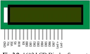
3.9. 16*2 LCD Display Segment: It has 16 pins. Out of which 8 pins are used to dump data in ASCII equivalent Binary form and for this the data is feed from a port of Microcontroller.
Fig 3.9: 16*2 LCD Display Segment
3.10. Relay-Circuit Breaker Circuits: It is a combination of a relay and a circuit breaker
Fig 3.10: Relay-Circuit Breaker
IV. DESIGN, CALCULATION AND OPERATION OF CIRCUIT
1.2 Design of circuit:
4.1.1. Power Supply Circuit: The input to the whole circuit is given from a 1-Phase 230V source which is stepped down to 5V DC using a circuit which is termed as POWER CIRCUIT. This circuit comprises of different elements like Transformer, Bridge rectifier, Capacitors, Voltage regulator, LED.
Here the transformer used is to step-down the voltage from 230 volts to 9volts.
Bridge rectifier is used for rectifying action, i.e. AC voltage is converted to DC Voltage.
Capacitor is used for maintaining healthy output without ripples.
Voltage regulator is used for to automatically maintain a constant voltage level of 5V DC.
LED it is used to indicate the activation of the power circuit. The power circuit described above is as shown in Figure 4.1.1:-
Fig 4.1.1: Power Supply Circuit
Vol. 04, Issue 04 (April. 2014), ||V2|| PP 01-07
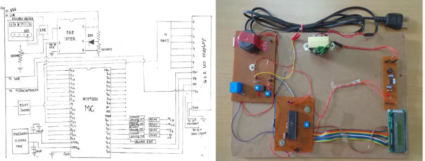
Fig 4.1.2: Controller Circuit
4.2 Operation of Circuit: The operation of the circuit is simple and easy. Firstly the input is tapped from a 230V AC Source and it is stepped down to 9V AC and then is converted to DC 5V by using a cascaded connection of a Bridge rectifier and a 7805-Voltage regulator. This 5V supply is used for 555, 8051MC, 16*2 LCD Display Segment. The data is completely controlled by using the instructions given in the controller. According to the instructions in controller, when the maximum demand crosses its specified value/range, the buzzer is activated(as an alarm/indication) and the amount of power being consumed is displayed on LCD Segment , and if the load is not set back within specified limits in the given time, one of the port of 8051MC(the port-as specified in the program) gets activated(active high state), then the signal from this port is driven and amplified by current driving circuit and is given to relay based circuit breaker and the load is tripped off.
Fig 4.2.1: Basic block diagram (Sketch) Fig 4.2.2: Implemented practical Main Circuit
4.3 Calculations:
In energy meter, the amount of energy being consumed is indicated by the blinking of a LED. Now by using this blinking phenomenon, the energy being consumed at each and every instant is analyzed (calculated) and is compared with the allowable/permissible maximum demand value.
i.e., with increase in load the number of pulses generated also increases with inturn reduces the time between two pulses, and it is given as:
Where Pulse distance is the measure of pulse width in time. For example,
Automation of Maximum Load Control using 8051-Microcontroller
Where, Pulse Distance1: Is the time period of the blink pulse under rating as specified for energy meter (for a 3200 blink meter its value is 3600/3200= 1.125sec/blink for 1kWh).
Energy consumed1: Energy consumption at the instant of pulse 1(basically its value is 1kWh)
And,
Where, Pulse Distance2: Is the time period of the blink pulse under loaded condition (its value is calculated by using a timer in controller).
Energy consumed2: It is energy being consumed at the loaded condition. Its value is calculated using the above formula.
For example:
Energy consumed1: 1kWh, Pulse Distance1: 1.125sec Pulse Distance2: 1.5sec (say) then
Thus calculated Energy consumed2 is compared with permissible limit/ pre-set limit value of maximum demand at every instant using controller.
V. PROGRAMMING DESCRIPTION
5.1. Introduction to programming:
A program is nothing but a set of instructions. And these instructions are given in form of programming. There are mainly two platforms for programming, they are:
1. Assembly Level Language, 2. Embedded-C.
The basic platform used for programming in this paper is Embedded-C.
5.2. Embedded C: Embedded C is a set of language extensions for the C Programming language by the C Standards committee to address commonality issues that exist between C extensions for different embedded systems.
5.3. Programming for Controlling Maximum Load Demand: Programming for controlling maximum demand is also done using Embedded-C.
6 6.1. Output:
How does this effect your bill?
This example shows how excess power consumption effects the consumer: Permissible maximum demand/ Contracted power: 70 kVA (say)
Now, consider a case of 30days, in which the maximum load is considered within the permissible limit i.e. 70KVA
Let, the no. of units consumed (in 30 Days): 11764 kVAH Tariff under normal condition:
Where ‘b’- charge per kVA of maximum demand, ‘c’- charge per kVAH of energy consumed.
And ,
Therefore, the value of tariff under normal working condition ( ): Rs 73967.2.
Now, consider a case with maximum demand crossing its limits beyond the permissible maximum demand value,
Maximum demand recorded (in kVA) (or) kVA-Demand meter reading: 125.43 kVA (>70 kVA), Excess power consumed: 125.43kVA-70kVA=55.43 kVA ,
kVA penalty *( ) : 55.43kVA.
Now under this condition the tariff rates are altered since the value of ‘b’ i.e. charge per kVA of maximum
demand is doubled and the modified tariff is as follows:
Tariff, when the consumer crosses the maximum demand limit:
‘c’- charge per kVAh of energy consumed,
‘ ’- kVA penalty (it is the excess power value that is consumed beyond permissible value).
and , ,&
Therefore, the value of tariff when the consumer crosses the maximum demand limit ( ): Rs 1,01,682.2
The difference in the tariff = -
= 1,01,682.2 – 73,967.2 = 27,715 Rs
Therefore, the change in tariff is: 27,715 Rs Percentage increase in tariff: 37.47%
This unwanted increase in tariff can be minimized by a reasonable extent.
6.2. Advantages:
This system of maximum demand control with 8051-controller is simple, sensible, reliable, fast, accurate.
It consumes very less power and is very compact.
It is very feasible, economical and has good efficiency.
6.3. Applications:
It can be installed in almost all kind of applications irrespective of the type of consumer.
It can be used directly for controlling the maximum demand by simply specifying the value in program.
It can also be used in different type of organizations like workplaces, colleges, apartments(main D.B., near
Transformer ),in all scales of industries(including large, medium &small scale)
VI. CONCLUSIONS
This paper has represented a novel strategy of controlling the value of maximum demand over a time period using a controller. The control is made with ease by using a controller with Embedded-C platform. The effects of uncontrolled maximum demands are illustrated above in this paper and based on those points it is strongly recommended for control of maximum demand in automated form (i.e. with least human effort) for all types of consumers.
REFERENCES
[1] ‘THE 8051 MICROCONTROLLER’, Kenneth AYALA, Cengage Learning
[2] ‘MICROPROCESSORS AND MICROCONTROLLERS’, N.Senthil Kumar, M. Saravanam,
S.Jevanatham, OXFORD University Press
[3] ’The 8051 Micro Controller and Embedded Systems’, 3rd-edition Muhammad Ali Mazdi, Janice Gillispie
Mazdi, Rolin D. McKinlay, Pearson Publications
[4] ‘A Course in POWER SYSTEMS’, J.B. Gupta, S.K.Kataria &Sons Publications.
[5] ‘Modern Power System Analysis’, D.P. Kothari, I J Nagarath, Tata McGraw-Hill Publications
[6] ‘Power System Analysis’ John J Grainger, William D Stevenson, Jr, Tata McGraw-Hill Publications
[7] ‘Electrical Power Systems’ C L Wadhwa, New Age International Publications