(UDC: 66.018.9:519.248)
Progressive damage modeling of porous composite materials by multi-scale
finite element method
Z.Q. Lian1,2, C.Y. Tang1, Z.W. Wang1,3, C.P. Tsui1*, M.Y.C. Pang4, W.O. Wong5, B. Gao6, C.L. Chow7
1Department of Industrial and Systems Engineering, The Hong Kong Polytechnic University,
Hung Hom, Kowloon, Hong Kong, P.R. China.
2State Key Laboratory of Structural Analysis for Industrial Equipment, Department of
Engineering Mechanics, Dalian University of Technology, Dalian, P.R. China.
3School of Chemical Machinery, Dalian University of Technology, Dalian, P.R. China. 4Department of Rehabilitation Sciences, The Hong Kong Polytechnic University, Hung Hom,
Kowloon, Hong Kong, P.R. China.
5Department of Mechanical Engineering, The Hong Kong Polytechnic University, Hung Hom,
Kowloon, Hong Kong, P.R. China.
6Department of Prosthodontics, College of Stamatology, The Fourth Military Medical
University, Xian, P.R. China
7Department of Mechanical Engineering, University of Michigan-Dearborn, Dearborn, USA.
*Corresponding author
Abstract
Porous composite materials have a wide spectrum of applications in the aerospace and marine industries and biomedical engineering. A multi-scale finite element method (FEM) incorporating the element-failure method (EFM) and the strain invariant failure theory (SIFT) was proposed to simulate the progressive damage of porous composite materials under compression in this study. In micro-scale, a three-dimensional FE repeated cell model was constructed to determine the mechanical properties of the base composite material. Moreover, two-dimensional porous repeated cell models in macro-scale were developed to predict damage propagation in the porous polymer composite. The porous models with three different arrays of pores were constructed to investigate the effect of spatial arrangement of the pores on the progressive damage behavior of the porous composites. Porous hydroxyapatite/ polyetheretherketone (HA/PEEK) composites under compression loading was chosen as a case example to illustrate the implementation of the proposed method. The simulation results showed that the proposed method was feasible and effective in simulating the progressive damage behavior of porous composite materials. The model with the hexagonal arrangement of pores was found to be more resistant to damage propagation under compression loading.
1. Introduction
Over the past few decades, polymers have been widely used to replace many of the conventional metals in various engineering and medical applications, because polymers possess some distinctive advantages such as ease of processing, lighter weight and lower cost. However, the stiffness of polymers cannot generally satisfy the engineering requirement for load-bearing applications (Kurtz et al. 2007) . As the stiffness and strength of polymer can be improved with addition of fillers such as fibers and particulates, the mechanical properties of the particulate polymer composites have been extensively studied in past decades (Cogswell et al. 1992, Tsui et al. 2004, Ichim et al. 2007). Various finite element (FE) models have been developed to study the effects of the fillers on the properties of various composites, so as to control the size, shape, amount and distribution of the fillers. Damage is one of the most important factors causing the failure of polymer biomaterials, especially under excessive loading (Ichim et al. 2007, Wiggins et al. 2003). Recently, particle-matrix debonding and micro-damage of the base material and interphase layer have attracted attention of many researchers (Wiggins et al. 2003, Tsui et al. 2001, Fan et al. 2004) for better prediction of the mechanical properties of polymer composites. At present, synthetic polymer based porous structures have shown promising performance in aerospace, marine, and biomedical applications due to many practical advantages arising from precise control of material composition, porosity, and micro- and macro-structural properties. Rezwan et al. have reviewed various techniques for producing porous polymer-ceramic composite structures of different morphologies, whose properties depend on not only the size and shape of the particle, but also arrangement of voids and porosity. Load-bearing capability of these structures could be significantly weakened by high porosity. Failure often occurs when the strength of the structural material cannot support the applied loading. Therefore, the design and fabrication of porous composite materials especially made of polymers with adequate load-bearing capability become an important research topic.
A scalar damage variable is often defined for depicting the degradation behavior of materials. For the conventional stiffness reduction approach, the values of certain material parameters in the constitutive equations will be reduced when damage occurs. However, the stiffness matrix of the FE model may become ill-conditioned, leading to divergence or instability in computation. For another approach called the element failure method (EFM) (Beissel et al. 1998), only the nodal forces of damaged elements are modified in the EFM. Therefore, the stiffness matrix remains unchanged in the whole simulation process, so that the aforesaid computation problem can be avoided. So far, the EFM and the SIFT (Gosse et al. 2001) have been applied for predicting damage, fracture, and delamination of composites (Tay et al. 2006, Tay et al. 2006, Tay et al. 2008). To the best of authors’ knowledge, their application in porous polymer composites has not been discussed in open literatures.
2. Material and methods
2.1 Choice of Material
Porous hydroxyapatite/polyetheretherketone (HA/PEEK) polymer composite materials have been used as a potential biomaterial for bone replacements and tissue engineering applications [10], and was used as the target material in the present work. HA is a bioactive material with the calcium-to-phosphorus ratio similar to that in natural bone. PEEK is a rigid semi-crystalline polymer which has superior mechanical properties and bone-like stiffness as well as many other benefits, such as good resistance to chemical, fatigue, wear and high temperature. The mechanical and biological properties of HA/PEEK porous composite can be controlled by a number of factors such as the pore architecture, porosity level, damage behavior of the constituent materials, and interfacial property between the matrix and the particle.
2.2 Multi-scale FE modeling process
2.2.1 Micro-scale FE modeling
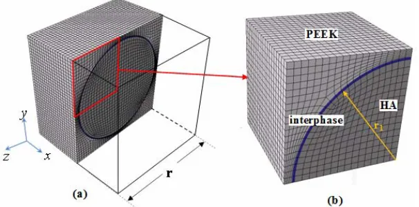
A three-dimensional (3D) micro-scale FE model (Fan et al. 2004) was constructed for predicting the mechanical behaviors of the base composite material, HA/PEEK. The FE model consisted of three different phases: a spherical HA particle, PEEK matrix, and the interfacial layer between the particle and the polymer matrix as shown in Fig.1(a). As reinforcing particles were assumed to be evenly distributed in the polymer matrix, a periodically repeated cubic array was employed to be the representative volume element (RVE) of the base material. Due to the symmetry for the packing of the spherical particles, only one-eighth of the repeated micro-cell as shown in Fig.1(a) was considered in the computation. The particle volume fraction (PVF) Vp is given by
3 1 4 ( )
3
p r V
r
(1)
where r1 is the radius of spherical particle, and r is the length of the micro-cell.
Fig. 1. Micro-scale cell model (a) RVE; (b) 1/8 RVE.
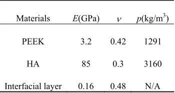
the interfacial layer was given to be one-twentieth of that of PEEK and the Poisson’s ratio was set to 0.48. The mechanical properties of the constituent materials adopted in the FE computation are summarized in Table 1 (Fan et al 2004, Wu et al. 1995).
Materials E(GPa) p(kg/m3)
PEEK 3.2 0.42 1291
HA 85 0.3 3160
Interfacial layer 0.16 0.48 N/A
Table 1. Mechanical properties of the constituent materials.
Due to the symmetry of the unit cell model as shown in Fig.1(b), the normal displacements (u, v, w) on the symmetrical surface in the (x, y, z) directions were constrained such that
0 on 0, 0 on 0, 0 on 0.
u x
v y
w z
(2)
Moreover, the symmetrical surfaces of the cell model were maintained to remain plane and parallel to their initial state after deformation, in order to ensure compatibility among all periodic representative cells.
2.2.2 Macro-scale FE modeling
In macro-scale, a porous composite material made of HA/PEEK under compression was studied. In general, the mechanical properties of porous composite material depend directly on the shape and spatial distribution of the pores. Three different spatial pore arrangements (Tay et al. 2008), namely, square, hexagonal and diamond, as shown in Figs.2(a)-(c), were employed in modeling the porous HA/PEEK composite. Two-dimensional plane strain macro-models were constructed to simulate the progressive damage process in the entire porous structure. Due to the symmetry of structural and loading property, a quarter of the entire porous structure was modeled (Fig.2).
a) (b) (c)
For computation in the macro-scale, the mechanical properties of the base composite material were represented mathematically by the Halpin-Tsai equations (Wu et al. 2002). The apparent Young’s modulus and Poisson’s ratio of the composite material are respectively given by 1 ( ) 1 (1 ) m f m f E E f
v fv f v
(3)
where Em and Ef are Young’s moduli of the matrix and the particle, respectively.
v
m andv
fare the Poisson’s ratio of the matrix and the particle, respectively. f is the value of PVF. The parameter is given by
( ) 1
( ) f m f m E E E E
(4)
where the factor
was used to describe the influence of filler geometry on a particular property. For the spherical particles, is in the following form,10 2 40f
(5)
For the three macro-models, the porosity was set to 0.4. The Young’s modulus and Poisson’s radio of the porous composite calculated from Eqs.(3)~(5) were equal to 8.6GPa and 0.37, respectively. In this simulation, the sizes of the HA particle and the pore were assumed to be in order of 10m and 1mm, respectively, for satisfying the dimensional requirement of RVE. The left line of all macro- models shown in Fig.2 were both constrained in the x and y
directions, while the right line was subjected to a controllable compression loading. The loading and boundary conditions in the three different spatial arrangements of pores are identical for comparison. The complete simulation was executed on an Intel Core i5/2.67GB computer with 4GB RAM.
2.3 Progressive damage modeling
The SIFT proposed by Gosse et al. 2001 was used as the damage criterion of polymer composites by amplifying the strain invariant quantities through extracting the information from the micro-scale FE models (Tay et al. 2005, Tay et al. 2008). According to the SIFT, there are three strain invariants. The first, second and third invariants, J1, J2 and J3 were defined as
1 x y Z
J (6)
' 2 2 2 2 2 2
2
1[( ) ( ) ( ) ] 1( )
6 x y y Z Z x 4 xy yz xz
J (7)
' 3 vm 3 2
J J (8)
Thirteen typical locations on the micro-cell model as shown in Fig.3 were chosen for extraction of the local strain amplification factors (SAFs). Points P1~ P4, I1~ I3 and M1 to M6 were located at the reinforcing particle, the interfacial layer, and the polymer matrix, respectively. The extraction method of SAF proposed by Buchanan et al. 2009 was used. For a prescribed point kth within the RVE, the strain, k
i
was obtained from the following equation:, ( , 1 6)
k k i Mij j i j
where k ij
M is the strain amplification factor matrix and j is the arbitrary state of strain applied to the RVE.
The components of the SAF matrix were determined uniquely by prescribing a canonical state of deformation and carrying out 3D FE analyses. For example, it was assumed that
0, (
2 6)
j
j
and
1
1
, then the strain,
ikbecomes,1 11 1 11 1 2 21 1 21 2
3 31 1 31 3 4 41 1 41 4
5 51 1 51 5 6 61 1 61 6
, or ; , or
, or ; , or
, or ; , or
k k k k k k k k
k k k k k k k k
k k k k k k k k
M M M M
M M M M
M M M M
(10)
Fig. 3. 1/8 of RVE; (b) 13 typical positions for the extraction of SAF from the micro-scale model.
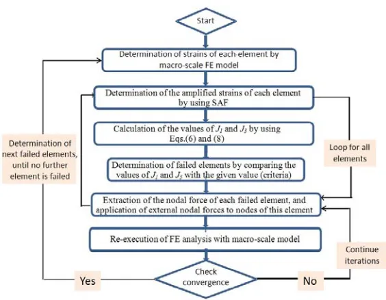
Figure 4 shows the flowchart for executing a simulation for the progressive damage process of the porous polymer composite material under compressive loading. The whole simulation process was realized using the commercial FE software named ABAQUS, while the EFM and the SIFT were incorporated into ABAQUS by writing a user-defined subprograms with Python based on ABAQUS Scripting Interface (ASI). Strains of each element were determined by multiplying the strains computed from the macro-scale FE model with the SAF. The values of
J1 and J3 were then calculated by Eqs.(6) and (8) based on the thirteen typical positions as
shown in Fig.3. Once the criteria for J1 and J3 were met, the nodal forces of each failed element
were extracted and external nodal forces would be applied to these nodes, while the material stiffness was kept unchanged. The steps for extracting nodal forces of failed element and their application as external forces to the nodes followed those reported by Tay et al 2008. Finally, the FE analysis of the macro-scale model would be re-executed. When a convergence was obtained, the whole program would be repeated to determine the next failed elements until no further failed elements could be found.
3. Results and discussion
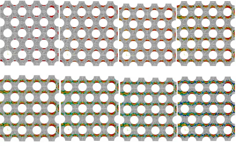
Figure 5 shows the progressive damage contours for the macro-scale model with the hexagonal arrangement of pores under compression loading, in which the elements with color denotes the failed elements. It can be seen that the porous polymer composite is gradually degenerated with increasing compression loading, because of increasing number of the failed elements. Moreover, it can also be observed that the damage is initiated at the vertical poles of the pores and then propagates progressively along the loading direction. The results demonstrate that the multi-scale modeling method is feasible for simulating the progressive damage of the porous polymer composite.
Fig. 5. The progressive damage process of the macro-scale model with the hexagonal arrangement of pores under compression loading (the damage progression starts from the upper
Figure 6 illustrates the damage contours of the porous polymer composites with three different spatial pore arrangements under compression. It can be observed that the damage propagation pattern is different in each case. For the hexagonal pore array, the damage propagates along the loading direction. For the square pore array, the damage propagates along the vertical direction. For the diamond pore array, the damage propagates along an angle of 45 degree with the loading direction.
a) b) c)
Fig. 6. Predicted damage contours of the three macro-scale models with different spatial arrangement of pores under compression loading, (a) Square, (b) hexagonal, and (c) diamond.
Figure 7 shows the progressive damage contours for three different cases under the same compressive displacement of 5mm. It can be observed that the model with the square pore array was not the worst one in terms of the capacity of resisting damage, because the damage was already localized across the regions connecting the pores along the vertical direction. On the other hand, the number of failed elements at the vertical poles of the pores in the model with the hexagonal pore array was less than those in the model with the diamond pore array, indicating that the model with the hexagonal pore array has the better capacity of resisting damage.
a) b) c)
Fig. 7. Predicted damage contours of the three macro-scale models with different spatial arrangement of pores under the same compressive displacement of 5mm,
4. Conclusion
The multi-scale FE modeling approach incorporating the EFM and the SIFT has been successfully developed to simulate the progressive damage processes of porous HA/PEEK polymer composites. This approach has shown to be effective in establishing damage criteria to identify the failed elements and enable the prediction for the progressive damage processes of the composites. The effects of three different pore arrangements on the porous composites could also be simulated so as to determine the preferred spatial arrangement of the pores. The model with the hexagonal array of pores has been found to possess higher capacity of resisting damage.
Извод
Моделирање
ширења
оштећења
прозних
композитних
материјала
помоћу
мулти
-
скалне
методе
коначних
елемената
Z.Q. Lian1,2, C.Y. Tang1, Z.W. Wang1,3, C.P. Tsui1*, M.Y.C. Pang4, W.O. Wong5, B. Gao6, C.L. Chow7
1Department of Industrial and Systems Engineering, The Hong Kong Polytechnic University,
Hung, Hom, Kowloon, Hong Kong, P.R. China.
2State Key Laboratory of Structural Analysis for Industrial Equipment, Department of
Engineering Mechanics, Dalian University of Technology, Dalian, P.R. China.
3School of Chemical Machinery, Dalian University of Technology, Dalian, P.R. China. 4Department of Rehabilitation Sciences, The Hong Kong Polytechnic University, Hung Hom,
Kowloon, Hong Kong, P.R. China.
5Department of Mechanical Engineering, The Hong Kong Polytechnic University, Hung Hom,
Kowloon, Hong Kong, P.R. China.
6Department of Prosthodontics, College of Stamatology, The Fourth Military Medical
University, Xian, P.R. China
7Department of Mechanical Engineering, University of Michigan-Dearborn, Dearborn, USA.
*Corresponding author
Резиме
Порозни композинтни материјали имају широк спекар примена у ваздухопловству и поморској индустрији и биомедицинском инжењерингу. У овом раду је предложена вишескална метода коначних елемената (ФЕМ) која обухвата методу отказа елемента
(ЕФМ) итеоријуотказазаснованунаинваријантамадеформација (СИФТ), засимулацију ширења оштећења порозних композинтних материјала услед компресије. На микро
-нивоу, конструисан је тродимензонални ФЕ модел са понављањем ћелија како би се одредила механичка својства основног композинтног материјала. Поврх тога,
дводимензоналнкимоделпорознећелијесапонављањемнамакронивоујеразвијенкако би се предвидела простирање оштећења упорозном полимерном композиту. Порозни модели са три различита реда пора су конструисани за испитивање ефекта просторне расподеле пора на понашање прогресивно оштећење порозних композита. Порозни
“хyдроxyапатите/ полyетхеретхеркетоне (ХА/ПЕЕК)” композит под копресионим оптерећењемјеизабранкао примерилустрацијеприменепредложене методе. Резултати симулације показали су да је предложена метода била изводљива и ефикасна за симулацијупонашањапрогресивногоштећењапорознихкомпозитнихматеријала, Модел сахексагоналнимраспоредомпорасепоказаокаоотпорнијинаширењеоштећењауслед оптерећењанакомпесију.
Кључнеречи: Мулти-скални, порозникомпозинтниматеријали, методаотказа елемената, Теоријазасновананаинваријантамадеформација, прогресивнооштећење,
References
Beissel SR, Johnson GR, Popelar CH. An element-failure algorithm for dynamic crack propagation in general directions. Engineering Fracture Mechanics 1998;61(3-4): 407-25. Buchanan DL, Gosse JH, Wollschlager JA, Ritchey A, Byron Pipes R. Micromechanical
enhancement of the macroscopic strain state for advanced composite materials. Composite Science and Technology 2009;69(11-12): 1974-78.
Cogswell FN, Leach DC. Thermoplastic structural composites in service. Plastics, Rubber and Composites Processing and Applications 1992; 18(4): 249-54.
Fan JP, Tsui CP, Tang CY, Chow CL. Influence of interphase layer on the overall elasto-plastic behaviors of HA/PEEK biocomposite. Biomaterials 2004;25(23): 5363-73.
Gosse JH, Christensen S. Strain invariant failure criteria for polymer in composite materials. Collection of Technical Papers-AIAA/ASME/ASCE/AHS/ASC Structures, Structural Dynamics and Materials Conference 2001; 1: 45-55.
Halpin JC. Primer on composite materials analysis, 2nd ed. New Holland, Lancaster, PA: Tchnomic Pub. Co. 1992.
Ichim I, Li Q, Li W, Swain MV, Kieser J. Modelling of fracture behaviour in biomaterials. Biomaterials 2007;28(7):1317-26.
Kurtz SM, Devine JN. PEEK biomaterials in trauma, orthopedic, and spinal implants. Biomaterials 2007;28(32):4845-69.
Rezwan K, Chen QZ, Blaker JJ, Boccaccini AB, Biodegradable and bioactive porous polymer/inorganic composite scaffolds for bone tissue engineering. Biomaterials 2006;27:3413-3431.
Tay TE, Liu G, Tan VBC, Sun XS, Pham DC. Progressive failure analysis of composites. Journal of Composite Materials 2008;42(18):1921-66.
Tay TE, Liu G, Tan VBC. Damage progression in open-hole tension laminates by the SIFT-EFM approach. Journal of Composite Materials 2006;40(11):971-92.
Tay TE, Liu G, Yudhanto A, Tan VBC. A micro-macro approach to modeling progressive damage in composite structures. International Journal of Damage Mechanics 2008;17(1):5-28.
Tay TE, Tan SHN, Tan VBC, Gosse JH. Damage progression by the element-failure method (EFM) and strain invariant failure theory (SIFT). Composites Science and Technology 2005;65(6):935-44.
Tay TE, Tan VBC, Liu GY. A new integrated micro-macro approach to damage and fracture of composites. Materials Science and Engineering B-Solid State Materials for Advanced Technology 2006;132(1-2):138-42.
Tay TE, Tan VBC, Tan SHN. Element-failure: An alternative to material property degradation method for progressive damage in composite structures. Journal of Composite Materials 2005;39(18):1659-75.
Tsui CP, Tang CY, Fan JP, Xie XL. Prediction for Initiation of Debonding Damage and Tensile Stress-Strain Relation of Glass-Bead-Filled Modified Polyphenylene Oxide, International Journal of Mechanical Sciences, 2004;46:1659-1674.
Tsui CP, Tang CY, Lee TC. Finite Element Analysis of Polymer Composites filled by Interphase Coated Particles. Journal of Materials Processing Technology, 2001;117:105-110.
Wiggins MJ, Anderson JM, Hiltner A. Biodegradation of polyurethane under fatigue loading. Journal of Biomedical Materials Research - Part A 2003;65(4):524-35.
Wu W, Sadeghipour K, Boberick K, Baran G. Predictive modeling of elastic properties of particulate-reinforced composites. Materials Science and Engineering A 2002;332(1-2):362-70.