efficiently and it reduces the stress on switches and require small filters since the frequency is higher when compared to single-phase topologies. An active clamping technique is employed by connecting the primary side of the transformer to the three-phase full bridge of switches and a clamping capacitor. The energy from the leakage inductances is reused in this circuit, thus efficiency of the converter is increased. The applications include fuel cell systems, transportation and uninterruptable power supplies that can benefit from the advantages presented by this converter.
I. INTRODUCTION
The space vector modulation (SVM) technique uses a fixed frequency in synthesizing the reference vector, enabling many power applications to lower their switching losses. This clearly improves the efficiency, which is vital for high power applications such as DC/AC converters that are interconnected to power systems through transformers. While the SVM can be practically considered as a voltage based technique for the AC/DC converter output, one should obtain the reference voltage vector based on the required objectives of a certain application. Unlike the voltage-based SVM techniques, the current-based modulation techniques (e.g. hysteresis modulation) impose high losses despite their easy approach towards providing required reference current vector. Hence, the problem can be narrowed down to two problems for the SVM technique; first, provision of a three-phase reference voltage vector for the AC/DC converter output, and, second, making up the provided reference vector using the different switching status produced by a three-dimensional SVM technique. The instantaneous phase quantities abc are transferred to the so called αβo space to achieve a better distinction of zero sequence component for four-wire systems, in particular the active power filter.
Sinusoidal PWM has been a very popular technique used in AC motor control. This relatively unsophisticated method employs a triangular carrier wave modulated by a sine wave and the points of intersection determine the switching points of the power devices in the inverter. However, this method is unable to make full use of the inverter’s supply voltage and the asymmetrical nature of the PWM switching characteristics produces relatively high harmonic distortion in the supply.
Three-phase systems are well known by their use in electric power generation transmission and distribution. The cost saving they provide by employing less material than single-phase systems assured success in these areas and led to three-phase rectifiers, inverters and also DC-DC converters. Industrial environments have an increasing need for high-efficiency DC-DC converters. Applications including distributed generation and uninterruptable power supplies generally count on single-phase DC-DC converters with big and heavy transformers.
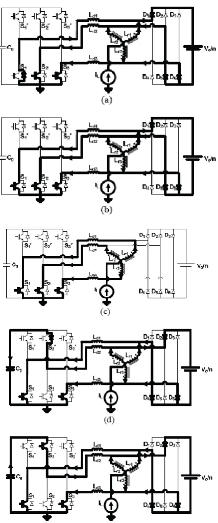
II. PROPOSED SV-PWM THREE-PHASE DC-DC CONVERTER A. Circuit Description
Fig.1 Circuit diagram of SV-PWM three-phase current-fed push-pull DC-DC converter
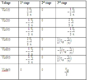
B. Simplified Circuit
The analysis can be simplified maintaining the same waveforms using the Fig 2 despite the complete circuit being shown in Fig 1.This circuit represents the non-isolated equivalent version of the proposed converter with current source input and voltage source output. The coupled three-phase reactor substitutes the transformer. The transformer was substituted by a coupled three-phase reactor. The voltages and currents from the secondary side are referred to the primary side in this circuit. During the description of the operation stages, the time intervals related to the commutations will not be considered due to being very short and interfering very little in voltage gain.
S1' S2' S3'
S1 S2 S3
Ld1
Ld2
Ld3
D4 D5 D6
D1 D2 D3
iCg (t) Lr1 Lr2 Lr3 . . . iLd1 (t) iLd2 (t) iLd3(t) niLs1(t) niLs2(t) niLs1(t) Vo/n nio(t) VLd1(t) VLd2(t) VLd1(t)
Fig. 2.Simplified non-isolated version of the active-clamped three-phase current-fed push-pull DC-DC Converter
C. Modulation
This PWM technique approximates the reference voltage Vref by a combination of the eight switching patterns (V0 to V7) Coordinate Transformation (abc reference frame to the stationary d-q frame): A three-phase voltage vector is transformed into a vector in the stationary d-q coordinate frame which represents the spatial vector sum of the three-phase voltage.
Fig.3 Basic switching vectors and sectors.
III. PRINCIPLE OF OPERATION AND VOLTAGE GAIN. A. Operation
The Proposed converter has nine topological stages per switching period that can be described as follows: Before the 1st stage; S1’, S2 and S3 are already conducting.
1] 1st stage (t0,t1) - This stage starts when switch s1 is turned on. Before this stage,S1’ was conducting and capacitor Cg was delivering energy. Current iLd1(t),initially negative and equal to -IL/3.It increases linearly through the diode of S1 as shown in Fig. 4(a) becomes positive and the value increases through S1 until reaching IL/3 as shown in Fig. 4(b). The currents iLd2(t) and iLd3(t) decreases from 2IL/3 to IL/3 through switches S2 and S3 respectively. The energy received by the load is from the commutation inductances through diodes D1,D5 and D6.The energy transfer from the source to load does not take place during this stage.
2] 2nd stage(t1,t2) – This stage starts when the currents iLd1(t),iLd2(t) and iLd3(t) egual to IL/3.The currents iLd1(t),iLd2(t) and iLd3(t) remain at IL/3 and the diodes of the rectifier remains in off condition. This is shown in Fig. 4(c). The energy is not transferred from source to load during this stage.
3] 3rd stage (t2,t3) – This stage starts when the switch S2 is turned off. The current iLd2(t) decreases linearly from IL/3 through the diode of S2’ as shown in Fig. 4(d) and then it equals zero. It then starts to increase negatively until it reaches –IL/3 as shown in Fig. 4(e). The energy from the commutation inductance is received by the clamping capacitor Cg as shown in Fig. 4(d). The capacitor Cg returns this energy as shown in Fig. 4(e). The currents iLd1(t) and iLd3(t) increases from IL/3 to 2IL/3 through the switches S1 and S3 respectively. The source transfers the energy to the load through the diodes D2, D4 and D6.
The fourth topological stage and the seventh topological stages are similar to the first stage. The fifth topological stage and eight topological stages are similar to the second stage. The sixth and ninth topological stages are similar to the third stage. The difference is that the other switches are on. The switching period is completed after the ninth stage and the new period starts with the first stage.
Fig 4. Topological Stages:(a) first stage – part 1, (b) first stage- part 2, (c) second stage, (d) third stage –part 1 (e) third stage-part 2
B. Voltage Gain
The average current through the clamping capacitor Cg is shown in equation (1)
3 𝑇𝑠 .
𝐼𝐿 3+
𝑉𝐿𝑑 2
𝐿𝑑 . 𝑡 . 𝑑𝑡 = 0 (1−𝐷)𝑇𝑠
0 (1)
The value of VLd2 is substituted during the third stage from the table I in (1) and solving the integral gives (2)
𝑉𝑐𝑔− 𝑉0
𝑛 = 𝐿𝑑. 𝑓𝑠.𝐼𝐿
The average voltage across the inductors is zero, so the average voltage across the switches S1, S2 and S3 is the input voltage Vi, and equation (6) can be written.
𝑉𝑖 = 1 − 𝐷 . 𝑉𝐶𝑔 (6)
Table IIMain Voltages during each topological stage
The equation (6) leads to
the input clamping capacitor voltage gain in (7). 𝑉𝐶𝑔
𝑉𝑖 = 1
1−𝐷 (7)
Substituting equation (4) in equation (7) leads to the input output voltage gain(8).
𝑞 = 𝑉0 𝑉𝑖=
𝑛
1−𝐷 +𝑛 .Ī0 (8)
Table III Equations for Time Intervals of Fig.4
Fig.4.Main theoretical waveforms for region R3
IV. SIMULATION RESULTS
*
Fig.6 Output voltage of ZVS-PWM three-phase current-fed push-pull DC-DC Converter First stage
∆𝑡1=
𝑛. 𝐿𝑑. 𝐼𝐿
𝑉0 Second stage
∆𝑡2=
𝑇𝑠
3 − ∆𝑡1− ∆𝑡3
Fig.7 Output current of ZVS -PWM three-phase current-fed push-pull DC-DC Converter
Fig.8 Output voltage of the Space-Vector-PWM Three Phase current-fed Push Pull DC-DC Converter
Fig.9 Output current of the Space-Vector-PWM Three Phase current-fed Push Pull DC-DC Converter
V. CONCLUSION
In this paper, a Space Vector –PWM Three phase Current-fed Push-Pull DC-DC Converter has been proposed. In this paper, a SV-PWM Three-Phase Current-Fed Push-Pull DC-DC Converter has been proposed.The operation stages were described and the main waveforms were plotted. The equations of voltage gain and equations involving the commutation parameters were derived to help the design process. By using SV-PWM instead of Sine-PWM, the output of the converter was increased and the ripple in current was also reduced. The proposed converter circuit was verified by Mat lab/Simulink with detail models.
REFERENCE
[1]. R.Prasad, P.D.Ziogas, S.Manias, “Analysis and design of a three-phase off-line DC-DC converter with high frequency isolation,” in Proc.IAS’88, 1988,pp.813-820.
[2]. L.D.Salazar, P.D.Ziogas, S.Manias, “Design oriented analysis of two types of three-phase high frequency forward SMR topologies”, in Proc.Fifth Annual Applied Power Electronics Conference and Exposition, APEC’90,11-16/Mar.,1990,pp.312-320
[3]. R.W.A.A.De Doncker,D.M.Divan and M.H.Kheraluwala, “A three-phase soft-switched high-power-density DC/DC converter for high-power applications”, IEEETrans.Ind.Applicat., vol.27,pp.63-73,Jan/Feb.1991.
[4]. J.Jacobs, A.Averberg and R.De Doncker, “A novel three-phase DC/DC converter for high-power applications” in Proc.Power Electronics Specialists Conference,PESC 2004, Aachen,Germany,pp.1861-1867,vol.3.
[5]. D.S.Oliveira Jr. and I.Barbi, “A three-phase ZVS PWM DC/DC converter with asymmetrical duty cycle for high power applications”,IEEETrans.PowerElectron.,vol.20,n.2,pp.370-377,Mar.2005.
[6]. D.S.Oliveira Jr. and I.Barbi, “A three-phase ZVS PWM converter with asymmetrical duty cycle
associated with a three-phase version of the hybridge rectifier”, IEEE Trans.Power Electron.,vol.20,n.2,pp.354-360,Mar.2005.
[7]. D.Segaran,D.G.Holmes and B.P McGrath, “Comparative analysis of single and three-phase dual active bridge bidirectional DC-DC-DC converters” in Proc. Australasian Universities Power Engineering Conference,2008,AUPEC’08,Sydney,NSW,Australia,Dec.2008,pp.1-6.
[8]. J.Aguillon-Garcia and G.W.Moon, “A High Efficiency Three-Phase ZVS PWM Converter Utilizing a Positive Double-Star Active Rectifier Stage for Server Power Supply”,IEEE Trans.Ind.Electronics,vol.58, no.8,pp.3317-3329,Aug.2011.
[9]. D.Vinnikov and I.Roasto, “Quasi-Z-Source-Based Isolated DC/DC Converters for Distributed Power
Generation”, IEEE Trans. Ind. Electronics, vol.58, no.1,pp.192-201,Jan.2011.
[10]. S.V.G.Oliveira and I.Barbi, “A three-phase step-up DC-DC converter with a three-phase high frequency
transformer” inProc.571-576 vol.2. IEEE International on Industrial Electronics, ISIE 2005,Dubrovnik,Croatia,June 2005,pp
[11]. R.L.Anderson and I.Barbi,“A Three-Phase Current-Fed Push-Pull DC-DC Converter”,IEEE Trans
Power Electron.,vol.24,no.2,pp.358-368,Feb.2009.
[12]. Romero L.Andersen and Ivo Barbi, , “A ZVS-PWM Three-Phase Current-Fed Push-Pull DC-DC