ISSN (e): 2250-3021, ISSN (p): 2278-8719
Vol. 08, Issue 7 (July. 2018), ||V (VI) || 01-06
FPGA Realization of Autonomous Chaotic Generator using
RK4-based Algorithm
1
Subodh Kumar Pandey,
2Sanjeev Kumar Gupta
1Research Scholar, Department of Electronics& Communication Engineering
Rabindranath Tagore University, Chiklod Road Raisen-464993 (M.P.)
2Professor and Dean Department of Electronics& Communication Engineering
Rabindranath Tagore University, Chiklod Road, Raisen-464993 (M.P.)
Abstract–
Now a days chaotic systems have an important role in secure communication and cryptography. As FPGA implementation have certain advantages over analog one, different chaotic system like chaotic oscillator, True random number generators and chaotic systems used in image processing, optical circuits for secure communications were successfully realized in FPGA. This paper presents FPGA implementation of Autonomous Pandey-Baghel-Singh chaotic signal generators using RK 4 algorithm. Numerical solution of Differential equation system is obtained and coded in Verilog and tested with Xilinx vivado 17.3 design suite in Artix-7 Nexus 4 DDR and Basys 3. Performance of the FPGA based chaotic generators is analyzed using 106data sets with the maximum operating frequency achieved up to 359.71MHz.
Key Words -
Chaotic Generators, RK 4 algorithm, FPGA--- --- Date of Submission: 13-07-2018 Date of acceptance: 29-07-2018 --- ---
I.
INTRODUCTION
Chaos generator is a fundamental block of any chaos based system. Basically chaos based system are used in secure communication and cryptography. Recently implementation of FPGA based real time chaotic oscillator using different numerical algorithm were presented and it was shown that the processing speed of FPGA is much higher due to parallel processing capabilities. Hence it may be interesting to see the performance of FPGA based different chaotic systems as the analog based design of chaos based generators is sensitive to initial conditions and acquires a large chip area. To avoid these problems Digital based design chaotic systems using FPGA can be implemented as FPGA implementation is more flexible architecture and have low cost test cycle and found more useful in chaos based engineering applications [1-7].
In II section of the paper presented the Pandey-Baghel-Singh Chaos System (PBSCS) is described along with their x, y and z signals and their attractors [8]. In the III section the mathematical models of PBSCS is numerically obtained with RK 4 algorithm and FPGA model of PBSCS is introduced. In the IV section simulation results has been presented and analyzed. In section V conclusion is given.
II. INTRODUCTION TO PANDEY- BAGHEL-SINGH CHAOS SYSTEM
Pandey-Baghel-Singh Chaos System (PBSCS) is defined by the set of differential equation (1) 𝑥̇ = 𝑦
𝑦̇ = 𝑧 (1)
𝑧̇ = −𝑎𝑥 − 𝑏𝑦 − 𝑐𝑧 − 𝑥2
Fig. 1: Time domain representation of x, y and z signals of PBSCS.
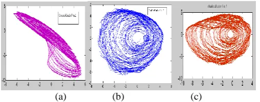
(a) (b) (c)
Fig.2: (a) x-y attractor, (b) y-z attractor, (c) x-z attractor
III.
RK
4
BASED
NUMERICAL
MODEL
OF
PBSCS
AND
ITS
FPGA
IMPLEMENTATION
For FPGA implementation of the system the numerical model is obtained using RK 4algorithm and coded in Verilog.
A. Numerical model using RK 4 algorithm
To construct the mathematical model of the PBSCS using RK4 algorithm, the system equation are represented as a function of 𝑓, 𝑔 𝑎𝑛𝑑 𝛿 as equation
𝑥̇ = 𝑓(𝑡, 𝑥, 𝑦, 𝑧) = 𝑦
𝑦̇ = 𝑔(𝑡, 𝑥, 𝑦, 𝑧) = 𝑧 (2) 𝑧̇ = 𝛿(𝑡, 𝑥, 𝑦, 𝑧) = −𝑎𝑥 − 𝑏𝑦 − 𝑐𝑧 − 𝑥2
With respect to above equation the mathematical model of the system using RK4 algorithm is given in equation (3). The parameter 𝐾, 𝜆 𝑎𝑛𝑑 𝜉 defined as the coefficients of the first, second and third equations respectively given in equation (2) and are placed in equation (3) to calculate the 𝑥(𝑘 + 1), 𝑦(𝑘 + 1) 𝑎𝑛𝑑 𝑧(𝑘 + 1) which are the values of the system after ℎ steps. The values 𝑥(𝑘 + 1), 𝑦(𝑘 + 1) 𝑎𝑛𝑑 𝑧(𝑘 + 1)are the output of the system after each interval which are used as initial conditions of the algorithm to calculate the values for the next cycle.
𝑥(𝑛 + 1) = 𝑥(𝑛) +1
6ℎ[𝑘1(𝑛) + 2𝑘2(𝑛) + 2𝑘3(𝑛) + 𝑘4(𝑛)]
𝑦(𝑛 + 1) = 𝑦(𝑛) +1
6ℎ[𝜆1(𝑛) + 2𝜆2(𝑛) + 2𝜆3(𝑛) + 𝜆4(𝑛)] (3)
𝑧(𝑛 + 1) = 𝑧(𝑛) +1
6ℎ[𝜉1(𝑛) + 2𝜉2(𝑛) + 2𝜉3(𝑛) + 𝜉4(𝑛)]
𝑘1= 𝑓[𝑥(𝑛), 𝑦(𝑛), 𝑧(𝑛)]
𝜆1= 𝑔[𝑥(𝑛), 𝑦(𝑛), 𝑧(𝑛)] 𝜉1= 𝛿[𝑥(𝑛), 𝑦(𝑛), 𝑧(𝑛)]
𝑘2= 𝑓[𝑥(𝑛) +
1
2ℎ𝑘1. 𝑦(𝑛) + 1
2ℎ𝜆1. 𝑧(𝑛) + 1 2ℎ𝜉1]
𝜆2= 𝑔[𝑥(𝑛) +1
2ℎ𝑘1. 𝑦(𝑛) +
1
𝜉2= 𝛿[𝑥(𝑛) + 1
2ℎ𝑘1. 𝑦(𝑛) + 1
2ℎ𝜆1. 𝑧(𝑛) + 1 2ℎ𝜉1]
𝑘3= 𝑓[𝑥(𝑛) +
1
2ℎ𝑘2. 𝑦(𝑛) + 1
2ℎ𝜆2. 𝑧(𝑛) + 1
2ℎ𝜉2] (4)
𝜆3= 𝑔[𝑥(𝑛) +
1
2ℎ𝑘2. 𝑦(𝑛) + 1
2ℎ𝜆2. 𝑧(𝑛) + 1 2ℎ𝜉2]
𝜉3= 𝛿[𝑥(𝑛) +
1
2ℎ𝑘2. 𝑦(𝑛) + 1
2ℎ𝜆2. 𝑧(𝑛) + 1 2ℎ𝜉2] 𝑘4= 𝑓[𝑥(𝑛) + ℎ𝑘3𝑦(𝑛) + ℎ𝜆3𝑧(𝑛) + ℎ𝜉3]
𝜆4= 𝑔[𝑥(𝑛) + ℎ𝑘3𝑦(𝑛) + ℎ𝜆3𝑧(𝑛) + ℎ𝜉3]
𝜉4= 𝛿[𝑥(𝑛) + ℎ𝑘3𝑦(𝑛) + ℎ𝜆3𝑧(𝑛) + ℎ𝜉3]
B. FPGA Implementation of Autonomous Chaotic Generator based on RK 4 algorithm
The PBSCS has been modeled using RK 4 algorithm and implemented with 32- bit IEEE 754-1985 standard on FPGA. Mathematical modeling is done in Verilog using Vivado design suite. Top-level diagram of RK 4based units have been shown in Fig. 3. A 32-bit input has been used and initial conditions are set in the beginning phase. The 32-bit signal are used as input parameter. There is three 32-bit output signals (Xn_out), (Yn_out) and (Zn_out) and ready signal is taken as one bit control signals for the proposed RK 4 based chaotic generators.
Pandey-Baghel-Singh Chaotic System based on
FPGA X_in[31:0] Y_in[31:0] Z_in[31:0] CLK Start RST Xn_out[31:0] Yn_out[31:0] Zn_out[31:0] Ready
Fig.3 Top level diagram of PBS Chaotic System based on FPGA
In Fig. 4 the 2nd level block diagram of the RK 4 based chaotic generator is presented. It have one multiplexer
and a chaotic generator unit which is FPGA based. The multiplexer is used to provide initial condition signals. For successive operation it is provided by the output signals. When enable is at logic high, the output generates chaotic signal. Multiplexer Xn_out[31:0] X_out[31:0] Y_out[31:0] Z_out[31:0] Reset Start CLK X_out[31:0] Y_out[31:0] Z_out[31:0] Ready h[31:0] Sel. Pandey-Baghel-Singh Chaotic System Yn_out[31:0] Zn_out[31:0]
The3rdlevel block diagram of the RK 4 based chaotic generator is given in Fig. 5. The proposed chaotic
generator consist of multiplexer, Ks units, Ys block and filter stage. Ks units calculate 𝑘𝑠, 𝜆𝑠 𝑎𝑛𝑑 𝜉𝑠 where 𝑠
varies between1 to 4. The 𝑥(𝑘 + 1), 𝑦(𝑘 + 1) 𝑎𝑛𝑑 𝑧(𝑘 + 1)given in equation (3)are calculated at Ys block.
The first value is generated after 142 clock Pulses and a feedback system is to be employed so that output is feedback to MUX after 142 clock pulses to generate next cycle. Filter unit stops undesired signal to reach output if generator does not generate any result.
Initial Condition
Input MUX
K1 Stage
K2 Stage
K3 Stage
K4 Stage
Ys Filter
Stage output
Fig. 5 3rdLevel diagram of RK 4 based PBSCS Generator Unit
IV.
SIMULATION
RESULTS
OF
PBS
CHAOTIC
GENERATOR
Fig.6 Timing simulation results of RK 4 based PBSCS obtained from Xilinx Vivado 17.3
Fig.7 Simulation result of PBSCS on Vivado 17.3
(a) (b) (c)
Fig. 8 (a) x-y attractor, (b) y-z attractor, (c) x-z attractor
Table 1: Final report of the resources consumption Maximum frequency (MHz) 359.71
No. of DSP 4
V.
CONCLUSION
The RK 4 algorithm based PBS Chaotic generator have been synthesized using the Nexus 4 DDR XC7A100TCSG-1 (Artix7) and Basys3 (Artix7) from the Xilinx Vivado v.2017.3 design suite. For the optimize result the clock period is set to 2.78 ns which uses2637 LUT’s and 4692 registers and the maximum frequency achieved is 359.71 MHz. The attractors generated for the FPGA based design are similar to PBSCS designed on analog platform.
REFERENCES
[1]. Ismail K., A. Tuaran O, Ihsan Pehlivan, “Implementation of FPGA-based real time novel chaotic oscillator”, Nonlinear dynamics (2014) ; pp. 49-59.
[2]. Murat Tunaa, Can Bülent Fidan, “Electronic circuit design, implementation and FPGA-basedrealization of a new 3D chaotic system with singleequilibrium point”, Optic ElsevierOptik (2016) pp. 11786–11799. [3]. S. Banerjee, J. Kurths, “Chaos and cryptography: a new dimension in secure communications”, Eur.
Phys. J. Spec. Top. , (2014) pp. 1441–1445.
[4]. I. Koyuncu, A.T. Ozcerit, I. Pehlivan, “An analog circuit design and FPGA-based implementation of the Burke-Shaw chaotic system”, Optoelectron. Adv.Mater. Rapid Commun. (2013) pp. 635–638.
[5]. L. Merah, A. Ali-pacha, N.H. Said, “A pseudo random number generator based on the chaotic system of Chua’s circuit and its real time”, FPGA Implementation (2013) pp. 2719–2734.
[6]. S. C¸ ic¸ ek, A. Ferikog˘lu, I˙. Pehlivan, “A new 3D chaotic system: dynamical analysis, electronic circuit design, active control synchronization and chaotic masking communication application”, Optik – Int. J. Light Electron Opt. (2016) pp. 4024–4030.
[7]. M. Tuna, I. Koyuncu, C.B. Fidan, I. Pehlivan, “Real time implementation of a novel chaotic generator on FPGA”, in: 2015 23rd Signal Processing andCommunications Applications Conference (SIU), IEEE, 2015, pp. 698–701.
[8]. Alpana Pandey, R. K. Baghel, R.P. Singh, “Analysis and Circuit Realization of a NewAutonomous Chaotic System”, International Journal of Electronics and Communication Engineering.ISSN 0974-2166 Volume 5, Number 4 (2012), pp. 487-495