910
Secure Routing In Vehicular Ad Hoc Networking
With Relay Node Against Black And Gray Hole
Attack
D. Silambarasan, Dr.P.Suresh
Abstract: VANeting a peculiar n/w with a dynamic topology that transfers messages or warnings between vehicles to Roadside units and between vehicles in all types of roadside regimes, including rural, urban, and highways. These communications bring all the roadside nodes to work together by setting routes and communication links. It also supports and offers intelligent transportation, comfort, security, and entertainment applications. The ―Wireless Access Vehicular Environment (WAVE)‖ standard in VANET has IEEE 802.11p / 609.3 standards at the lower/advanced level of the network layer, respectively. This network (n/w) has rapidly changing topologies with high mobility. The warning messages alert others to prevent collisions and traffic accidents and thus reducing roadside issues. Designing a routing protocol for this dynamic topology involves a lot of challenges such as packet loss, delay, latency, security threats, etc. The proposed model aims to improve the vehicular system by employing the Relay Driven Backbone network where the vehicles are elected automatically as Relay and Distributed Broadcasting Protocol is used for Data Communication. Two security threats Black, Gray hole, and broadcast storm problem in broadcasting are discussed. Proper implementation is ensured to prevent those threats. For Simulation evaluation of proposed models NS-3 is used. The parameters PDR, Throughput, PLR, E2E Delay are addressed in addition to compared with existing models.
Index Terms : VANET, Relay Node, Black Hole, Gray Hole, Broadcast Storm Problem.
—————————— ——————————
1.
INTRODUCTION
Vanet is based on the principles [1] of mobile ad hoc, which dynamically create the node in the highway for exchanging data. It is firstly introduced for ―car-to-car‖ communication where the info can be relayed between them. VANET go round all vehicles into a wireless router, with the distance from 100 to 400 meters to join and form a link with a range. As one gets out of the signal and leaves, others can join in. The first systems that will begin this may be a fire service and traffic police to communicate for safety purposes. An electronic device ‗On Board Unit‘ is on each vehicle that passes messages between the vehicles and also receives through the wireless ‗RSU.‘ This operates without any permanent infrastructure. The transmission range is 1000 m, as examined by the USDOT. There are also multimedia and web connection within the wireless coverage of every car. An OBU is a mobile, and RSU is a not moving node. An RSU can get the Internet through the port. It can communicate directly / by multi-hop. The two types of domain Access is Hot Spot and RSU. OBUs‘ may communicate with net via this RSU or HS. Also, by mobile n/ws for example ―GSM, GPRS, UMTS, Wi-MAX, and 4G,‖
1.1. Characteristics of VANET Dynamic topology
Periodic connectivity
Mobility Patterns
High storage capacity
1.2. Requirements in VANET
Integrity & Authentication – Message is verified for authorized identification and correct delivery.
Confidentiality – Transmission should be kept secret by using encryption schemes.
Anonymity & Privacy – Messages should be transferred to authorized vehicles only.
Access Control – Ability to receive services offered by long-distance vehicles.
Non-Repudiation – Senders of the message should not
deny, which will weaken the co-operation.
ID Traceability – The ability to get real identities of
vehicles and owners who sent messages.
Scalability – Accepting vehicles without any loss in
transferring, which will reduce the performance.
Efficiency and Robustness– Ability to give service under
different attacks.
Availability –Ensure communication even in adverse conditions or false events.
Confrontation beside ‘In-Transit-Traffic & Involved-Tampering’ – Protection against the corruption of data by
the Malevolent vehicle and tracing the unique detail of the position and velocity.
__________________________________
• Research Scholar, Department of Computer Science, Salem Sowdeswari College, Periyar University, Salem, India Email: [email protected],
911 1.3. Architecture of VANET
The three types [6] of architecture are:
The Free Region – made of vehicles /devices.
Infrastructure Region – consists of internet and private infrastructure.
Common Region – consists of roadside infrastructure.
2.
PACKET
ROUTING
PROCESS
IN
VANET
It acting a very important function in packet transmission [11] [12] is a procedure that is considered for forwarding the info. from Source – Destination node as comprehensive in the procedure. The routing depends on Topology, Position, Geo cast, Cluster, and Broadcast.
2.1. Categories:
2.1.1. Topology - IP addresses are used to identify the nodes
(vehicles) and to set up the routes. It identifies the best way to forward data. They are categorized as reactive, proactive, and hybrid, where the hybrid one uses both reactive and proactive.
a) Proactive - The info. of routing, in particular the Nxt-hop, is retained in the table. The access in the table shows the Nxt-hop toward a definite target node. Every one sends periodical information about its tables. These routing tables have information about its surrounding nodes. It also conveys information about the hop if it exists.
b) Reactive - Search the route to a target after a node interested to start a session with that destination and hence notable is found. It begins the communication only while it is essential for a node to correspond with n/w nodes. It keeps only that routes which are at present in use and reduce the load on the n/w.
c) Hybrid - A permutation of proactive/reactive protocols. The aim is to reduce the overhead and get moving the PDR to target with the use of the reactive/proactive protocol. This protocol separates the n/w invariant neighborhood. The protocol is deliberate in a way, and if the location info. of the vehicle reduce the n/w performance, it will robotically switch to reactive routing.
2.2. Location -Location information of a particular node is
used for communication. So, everyone is conscious of its place, the location of neighbor in the range, and a destination node through GPS or by some other positioning devices. The node use broadcast to know the location of one hope neighbor. This protocol incorporates minimal routing overhead and also avoids delay and latency.
2.3. Cluster –Sensor nodes are split into the number of clusters with assignments. The node is elected as the cluster head if it has the lowest or highest ID in the neighborhood. It is responsible for data dissemination. This topology uses two data structures, namely Cluster adjacency table and two-hop topology database. Initially, the head sends the request; the other participating node receives it and sends it to the next cluster head.
2.4. Broadcast - Transmits messages away from the
broadcast array with multi hops. It sends a packet to all nodes in the n/w using flooding. These make sure the complete PDR. Instead, bandwidth is loss, and the node also receives duplicate packets. In VANET, it accomplishes improved for a smaller nodes.
2.5 Geocast - Delivers the packet beginning of Src Node to all
n/w nodes within a precise geographical neighborhood. The vehicles external the zone are not cautioned. It is considered a multicast service. The source follows typically a forwarding scheme where it orders the packet flooding. Thus, decrease message overhead and n/w jamming. In destination, unicast direction-finding can be used to onward. These are used to send a message to all vehicles in a pre-determined geographical area.
3.
LITERATURE
REVIEW
912
hoc increases, there should be an efficient protocol to implement. The work presented 10 distribution protocols, and their policy is listed. These analyses travel around impulse, designing, and outline the development. Waghmode et al. [14] proposed a security-based protocol in VANET. Vehicles correspond surrounded by them and with infrastructure by disseminating secured/non-secured info. VANET is in safety on the road by introducing several safety applications. Security and safety are primary issues to keep away from intimidation in the n/w. To achieve this, the paper put forth a onetime authentication for group-based v-v communication by using symmetric group keys within the group. This mode of system can find a malevolent vehicle that creates a fake message. The cost is also enhanced as againts and examined with the existing methods. Xianfu Chen et al. [15] design a protocol that assures a lightweight and reliable one for dissemination in VANET. The multi-hop scheme is followed, and it avoids the collision. This paper proposes a lightweight protocol. This employs the backbone node to disseminate. It reduces contention time and maintains a high dissemination ratio. The backbone nodes are chosen automatically with the ‗hello message‘ and are exchanged by taking the movement and link capabilities. The paper reduces the overhead and improves the reception probability.
4.
METHODOLOGY
4.1. Existing Work: 1MIVANET (Mobile Infrastructure -VANET Model)
This work proposes a 2-Tier structural design ―Mobile Infrastructure in VANET (MI-VANET)[4]‖. This scheme is used in urban scenarios to use the Manhattan model. In high tier, the buses comprise a portable determination for PDR as the source, and the deep layer has cars and passengers as the destination. The lower tier does not forward for other nodes; only the high tier does. The lower sends the message to others through the more top tier. So, there must be more links in the higher tier for end-end connectivity. The high tier has interfaces to communicate with others, and they are wireless. This link a node to the n/w where transmissions are assigned and accepted. It is the combined structure of physical and logical components. They are the entity over which the wireless connectivity and security settings are applied. It improves n/w integrity. The ―Mobile Infrastructure Registering &Routing‖ is used for communication. The use of routing obtains the bus link information.
4.2. Mobile Backbone (MBN)
In this structure, some nodes influence others in the n/w. They will serve as ‗Mobile Backbone‘ and provide extreme communication. It is comprised of 2 kinds of nodes.
Static nodes, with limited capabilities, referred to as Regular Nodes (RNs).
Mobile nodes with extreme communication referred to as a backbone node.
This construction overrides other aspects of the performance, including scope, quality, reliability & scalability. ―Mobile Infrastructure Registering and Routing‖ are used for communication. Both techniques come under reactive location protocol.
4.3. Manhattan Model
This model has the map oriented Geographical restriction Pathway, which is defined in prior either randomly or defined as per the route of a real city. The vertex denotes the apartments, and the edge indicates the path and freeways. The nodes travel on the pathways. The mobile nodes move in X and Y direction on the map. This model follows a probabilistic scheme in the selection, so that at each intersection, a vehicle moves in one direction. For example, the probability of moving straight is ‗.5‘, and for left & right is ‗.25‘. The node will move along the grid of streets on the map. At an intersection, the node can move straight, left, or right with the defined probability.
4.4. Location Routing Protocol
The geographical location of the node is evaluated to select the best path. Each node determines the location itself and destination. The functionality is split into three different aspects:
i.Path selection, ii.Forwarding and iii.Recovery.
Every node gets its neighbor by ‗GPS‘ information. It doesn‘t have any routing table. ‗Hello, or beacon messages‘ are called for updating. A source has hello messages to find its neighbors. A location detail is stored in the header. The information is identified by location services. These protocols don‘t need any route maintenance and can be established when there is a need.
4.4.1. Advantages Lowest overhead,
More suitable for distributed nodes
4.4.2. Drawbacks
The Manhattan model only works in upright and straight pathways, so it can‘t be implemented for highways.
The MBNs‘ must be placed such that every RN can directly communicate with at least one in the link.
This model was always looking for buses for MBN, while the VANET is dynamic.
Packet Loss continuously increases with speed.
This protocol has a high latency.
Deadlock will occur in the location server.
4.5. Existing work:2 – MPLS (Multi-Protocol Label Switching Model)
This backbone n/w provides high bandwidth [3] facilities and services to vehicles. It has a wired mechanism with reliability and protection. It uses IEEE 802.11 standard, in which the units are tied via digital subscriber line and LAN connections and form a backbone. These types are usually employed in urban towns and on highways for managing the traffic. In earlier systems, the central devices are connecting with dedicated interfaces. But now integrated interfaces replace the IP-based systems.
913
transmission on the ‗local-local and local-remote nodes. It works in-between the 2nd and 3rd Layer, so it is denoted as ‗Layer 2.5‘.
4.6. MPLS Header
The header consists of:
1.Label – 20-bit identifier field.
2.Class of service –3-bit experiment field.
3.Stack field – 1-bit ordered set with a unique function. 4.Time to live – 8-bit time field.
4.7. On-Demand Routing Protocol (AODV)
AODV is a immediate protocol, which implies that it will search a path only if there is a need for sending data from SRC to DEST; thus, the overhead gets reduced. Each table entry has the subsequent in order:
DEST
NXT and No. of hops
Sequence No.
Lively neighbors and
Expiry time.
4.7.1. Control Messages
1. Request - When a route is unavailable to reach, the ‗RREQ‘ is passed on the net.
2. Reply Route - If a node has a consistent way to the destination, it sends a reply msg. ‗RREP‘ to the host.
3. Route error - Each node monitors its individual Nxt node. When a node inactive gets lost, an error message ‗RERR‘ is formed for notification of the loss.
4. HELLO, messages - Every node introduces its neighbor by using ‗HELLO‘ msgs to inform the Nxt nodes the connection is active.
4.7.1.1. Advantages
1. Provides Quality of Services. 2. Increase throughput.
3. Packet loss is less.
4.7.1.2. Drawbacks
The Manhattan model only works in X & Y pathways, so it can‘t be implemented for highways.
The MPLS Backbone architecture is expensive, less protective, and there is a need to employ a large number of Units.
Any disruption in the MPLS n/w can collapse the whole transportation and the re-direction of packets.
AODV collects a minimal amount of routing information in speed mobility.
Uncontrolled flooding in routing protocol may cause many repeated transmissions, which are called ―Broadcast-storm-problem.‖
4.8. Proposed work – RBSM (Relay Backbone Secured Model)
The proposed work is implemented in two phases.
Phase – 1 carries the relay node selection without a black hole.
Phase – 2 carries the scheme for black and gray hole prevention.
4.9. Working principle of the proposed scheme
The source on the highway generates the [7] messages in the occurrence of a collision, road disorder, or dangerous accident. The message is sent to the nearby Unit. The RSU selects any one of the vehicles within its coverage area (1000 m) as a relay to pass the message. To disseminate to all other nodes within its coverage area (250m), the relay node broadcast through the On-Board equipped in it and thus formed the ―Relay Backbone Model.‖ Both these formations extend the RSU coverage and limit the RSUs‘ to be installed. It is a one-hop interaction between the RSU and the relay node, and thus, it offers quick dissemination of data. The selection of the relay relies on the speed, distant from the danger zone, and the lane number which it is traveling. If the relay goes beyond the coverage, another relay is selected until the timer expires, and the message is deleted. Each checks the message for duplication. If so, it discards merely instead of broadcasting. The vehicle can also get other non-safety applications and infotainment applications through the Units. The RSU can connect to the net via hotspots or gateways The ―IEEE 802.11p - ―Wireless Access for Vehicular Environment (WAVE) – IEEE 1609.3‖ is opted for communication. It has 10 MHz bandwidth and a bit rate of 27 Mbps. Also, it provides exchanging of messages in-between vehicles in high motion and the road-side transportation in the ITS- 5.89 Ghz‘. In this protocol, the vehicles send info. regarding node congestion details such as speed, distance from other vehicles, etc. to close at hand vehicles. And it has CSMA/CD collision protocol to lessen the collision during node transmission. For efficient routing of packets, ―Distributed Vehicular Broadcasting protocol (DV-CAST)‖ is employed. It has efficient access in the Sparse, Regular, and Dense regimes of the highway. The three suppression schemes with Black and Gray hole routing protocol security attack prevention are included for a high packet delivery ratio and to eliminate the ―Broadcast storm problem.‖ For vehicle-vehicle communication, On Board (OBU) is installed with each one. The ―Dedicated Short Range Communication (DSRC)‖ standard in this unit can trace the neighbor vehicle and transmit the message. The proposed work chooses the freeway model to work on highways as it has no obstacles and crossings on the road. This model works for 4 Lane road.
4.9.1. Free-way model
It addresses the characteristics and integrates [5] the lane into the models and is categorized as ‗Model with Geographic Restriction,‘ and it works for a city model. The map is pre-entered in the simulation either in random or be defined on the map. The vertices denote the buildings, and the edges indicate the ways.
4.9.2. Black-hole Assault
914
being developed in Wireless service as it has various architecture. The hosts advertise it as the shortest path towards a destination, and it leaves the packets without informing the source. Finally, the message is not reaching to the intended target.
4.9.3. Gray Hole Attack
An extension of a black hole attack. [6] [10] here, the malicious node acts like the black node, but it loose the packet partially, not wholly. This attack to end with interference the whole n/w‘s presentation by nosy in the process. It is done in the following ways:
1. Put off inward packets but permit some PD.
2. Perform as usual for normal time and abnormal for a exacting time.
4.10. Phase – 1
4.10.1. Selection of relay node with black hole prevention
The ‗Relay‘ is chosen derived from measures ‗speed, distance, position, and Lane number.‘ The node is not allowed to introduce itself as having the shortest path. Instead, the relay node is picked by the roadside unit itself by considering the measures as mentioned above in the algorithm. When the Unit selects the relay, it sends the number of packets received, to the Unit as an acknowledgment within the prescribed time limit, if it doesn‘t respond the node is considered as a black hole, and the relay node is deleted from the RSU register and search for another node for the relay. If it responds, a target value is calculated by comparing the send and received the number of packets for the full message.
4.10.2. Relay node selection algorithm
Procedure Relay Node Selection without the black hole Receive a message from source (V-ID, Lno, msg) Check V-ID of the source in RSU
For V-ID in the RSU
If (Spd < 90 km/hr > 60 km/hr, Npos – RSUpos = low, Ndis – Sdis =low, Nlno – Slno) then
Set V-ID = RN
Calculate target value within prescribed time
If (Send (RSU) Packet size = Received (Node) Packet size) Store RN in RSU
Return. Where,
V-ID is vehicle identity, Lno is lane number, msg is message, spd is speed, N(pos) and RSU(pos) are Node and roadside Unit position, N(dis) and S(dis) are Node, and Source distance, N(lno) and S(lno) in Node and source lane number.
4.11. Phase –2
4.11.1. Tag Scheme Delivery
With the extension of the above algorithm, the packet drop is reduced by path tracing. The picked relay node is assessed by employing ―Tag Scheme Delivery (TSD).‖ In this method, the message to be forwarded is attached to a header called ‗Tag.‘ It is associated with the information ―Message, Packet Number, Size, Tag number, Counter value, Destination address.‖ All this information is attached and traced by the Roadside Unit. The tag number denotes the number of the relay node with its ID. The counter is set to the pre-defined
value. For example, if it is set to six, the relay node is considered as the sixth one. The counter value will be set to zero when it broadcast the message to five of its neighbors as the counter value is decremented. If the counter is not decremented, the relay node doesn‘t transmit the signals, and it is considered as a black hole. The destination or the neighbor node of the relay responds by sending the same tag as an acknowledgment to the Unit instead of the relay node, thus ensures the successful packet transmission. So, this combined technology gives a valid result, and the information delivered adequately.
4.12. Combined algorithm for Black and Gray hole during Packet dropping
Procedure Tag scheme delivery
Receive msg from the source node (V-ID, Lno, msg) N1: Check V-ID of the source in RSU
For V-ID in the RSU
Search for relay node with (Spd < 90 km/hr > 60 km/hr, Npos – RSUpos = low, Ndis – Sdis =low, Nlno – Slno) then Set V-ID = RN
Calculate target value within the prescribed time If (Send (RSU) Packet size = Received (Node) Packet size)
Store RN in RSU.
Send (msg, Pno, Psz, Tno, Cvl = Target value, Dead) to relay node
For timer < specified
If message transmitted to relay‘s neighbor Cvl--;
If label Cvl is not decreased and acknowledgment not received from the neighbor node
Mark it as Black and Gray hole Go to N1.
Where,
msg – message to be transmitted, Pno - packet number, Psz - Packet size, Tno - Tag number denotes the relay node number with its ID for each transmission, Cvl – counter value that is set to some predetermined number which means number of neighbor to be transmitted by the relay, Dead - the address of the destination from the roadside unit and it denotes the relay node address.
4.13. Routing Protocol with broadcast suppression technique: DV-CAST (Distributed Vehicular Broadcast Routing)
It is a neighbor knowledge broadcast scheme which has [9] local connection information for broadcasting messages. Broadcasting refers to dissemination from a single one to the entire node in its coverage area. Each vehicle frequently watches its local connection to assess the state of operation during packet arrival. Everyone has a GPS communication device. It finds whether the neighbor is ‗well or sparsely or fully disconnected.‘ So, the local topology detail is a must factor. This is available by the local information provided by one-hop neighbors through a ‗Periodic Hello Messages.‘
4.13.1. Parameters in DVCAST
Flag variable - check whether the message is a repetition or not.
915 Message-Direction Connectivity (MDC) - determines
whether the last vehicle is in the group.
Opposite-Direction Connectivity (ODC) - determines whether it is connected partially to one vehicle in either direction.
4.13.2. Description
If MDC is 1 → A dense region so suppression should be applied to handle the broadcast problem.
If ODC is 1 → , the Message is rebroadcast to get the destination.
If DFlg is 0, → It is a relay.
If DFlg is 1, →The node discards the duplicates by having the suppression scheme.
4.13.3. Broadcast storm Problem
The perfect communication system to transmit safety messages is broadcasting. Flooding is the simplest one to transfer to all vehicles in their radio transmission boundary [16] [17] [18]. But it introduces the ‗broadcast storm‘ and redundant message retransmission. Insignificant flooding or blind flooding, a node transfers a message, which is got by all neighboring ones within the boundary. When many nodes in the same transmission boundary re-broadcast the identical message, there occurs a contention, and it leads to collisions in the MAC. This called a ―Broadcast Strom Problem.‖
4.14. Weighted Suppression scheme
i. Weighted p-persistence - A Probabilistic based technique. While receiving a message from a node, the receiving node will check the packet ID to know the frequency of the message. If it is the first time it receives, then re-broadcasts with pab; If not, then it is discarded.
ii. Slotted 1-persistence – A timer-based scheme. While receiving, a node checks the ID for the frequency to make sure no duplicates have received before the time slot, then rebroadcasts with the timeslot if it is not, then discarded.
iii. Slotted p-persistence – A timer-based suppression technique. While receiving, a node checks the ID for the frequency to make sure no duplicates have received before the time slot, then rebroadcasts with the pre-determined probability with the timeslot if it is not, then discarded.
4.14.1. Advantages of the proposed system
Less need of RSU and provides Quality of Services.
Reduction in E-2-E delay,
Provides high PDR
Provides reduction in the redundancy and loss ratio,
It doesn‘t require any prior details about topology.
Implementation of security alerts against Black and Gray Hole.
5.
RESULT
AND
DISCUSSION
All the phases executed in NS-3 for receiving and sending the packets. It‘s a discrete-event computer NS.
5.1. Simulation setup
TABLE 1 SIMULATION SETUP
Parameter Value
Highway segment size 1000m Number of Lane and RSU 4 Lane, 1 RSU Mobility Model Freeway mobility model MAC Protocol IEEE 802.11p, IEEE 1609 Vehicle speed limit 60-90 km/ hr.
Vehicle density 25, 30, 35, 40, 45, 50
Packet size 512 bytes
Frequency band, Channel bandwidth 5.9 GHz, 10 Mhz
Bit rate 27 Mbps
Routing Protocol DV-CAST
Simulation Time 6000ms
Table .1 shows the simulation parameters used in this work.
5.2. Results
5.2.1. End-to end delay – Time is taken for a packet to
cross from source to destination.
Figure 1. Delay
Figure 1. shows the delay is decreased as the number of nodes increases in the case of the relay node in VANET.
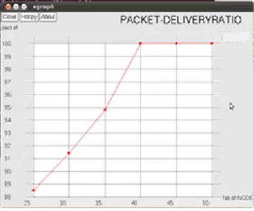
5.2.2. Packet delivery ratio - Ratio of packets received
successfully to the destinations.
916
Figure 2. shows the delivery ratio is low for the sparse region and regular regions but very high in the dense region for the high node coverage without the broadcast storm problem in the DV-CAST broadcasting protocol.
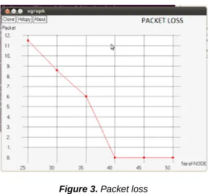
5.3.3. Packet Loss - Measured as a percent of packets
losses concerning the percentage of packets sent.
Figure 3. Packet loss
Figure 3. loss in the regular and sparse regions for the non-coverage area, but in the dense, there is very little loss.
5.3.4. Throughput – Total bytes/Packet size * simulation time
(in sec.)
5.4. Performance analysis
TABLE 2
RESULT WITH EXISTING AND PROPOSED
Parameters/ Model MI-VANET MPLS RBSM Average Packet Delivery
Ratio 82.1 94.3 96.5
Average Packet Loss
Ratio 17.9 5.7 3.5
Average Throughput 18 26 31
Average End to End
Delay 8.7 5.3 4.7
Table 2. Shows the comparison of existing and the proposed scheme RBSM in terms of four parameters.
VI.
CONCLUSION
AND
FUTURE
WORK
The VANET has frequent changing topology, and the nodes are in the highest motion, so a lot of n/wing issues are there. The proposed Secured Relay node Distributed Data Broadcasting with the prevention of Black, Gray hole and suppression techniques to overcome broadcast storm problem overcome the issues. The proposed method is also suiting for rural, urban, and highways. For Simulation, n/w Simulator is used. In the Simulation, it is proved that the ‗RBSM vehicular system‘ has more advantageous than the existing ones. In the future, the work can be extended by implementing other
routing algorithms in the variant pathway model. Also, other n/w security issues can be taken into consideration.
REFERENCES
[1] Advances in Vehicular Ad-Hoc Networks: Developments
and Challenges, by Mohamed Watfa, Publisher: IGI Global, Release Date: May 2010, ISBN: 9781615209132.
[2] Izhak Rubin, Andrew Horng, Chun-Yu Yang, ―Lane
Based Backbone Synthesis Protocols for Vehicular Ad Hoc Networks,‖ IEEE 2014.
[3] Kashif Naseer Qureshia, Abdul Hanan Abdullaha, Saleem Iqbala, zia Muhammad, ―Improving Quality of service through Back-Bone Network in Vanet,‖ Journal Teknologi, 2016.
[4] Luo. J, X. Gu, T. Zhao, and W. Yan. 2010. MI-VANET: a new Mobile Infrastructure Based VANET Architecture for Urban Environment in Vehicular Technology Conference Fall (VTC 2010-Fall). IEEE 72nd. 1-5.
[5] Manjot Kaur, Sukhman Kaur, and Gurpreet Singh, "Vehicular Ad Hoc Networks," Journal of Global Research in Computer Science, 2012.
[6] Sudhakar Sengan & Chenthur Pandian S, 2013, ‗A
Trust and Co-Operative Nodes with Affects of Malicious Attacks and Measure the Performance Degradation on Geographic Aided Routing in Mobile Ad Hoc Network‘, Life Science Journal, Vol. 10, No. 4s, pp. 158-163, 2013.
[7] Megha Nema, Prof. Shalini Stalin2 and Prof. Vijay
Lokhande "Analysis of Attacks and Challenges in VANET" in International Journal of Emerging Technology and Advanced Engineering, Volume 4, Issue 7, July 2014.
[8] Patrick I. Offor, "Vehicle Ad Hoc Network (VANET): Safety Benefits and Security Challenges," Social Science Research Network, 2012.
[9] Sudhakar Sengan, Chenthur Pandian S, 2015, ―Analysis of attribute aided data aggregation through dynamic routing in wireless sensor networks‖, Journal of Engineering Science and Technology, School of Engineering, Taylor‘s University, Vol. 10, No.11 (2015) 1465 - 1476ISSN: 1823-4690
[10] Poonam Dhamal, ―Broadcasting Routing Protocols in VANET,‖ IISTE, ISSN: 0974-6471, Vol. 4, No. (2), Dec 2011.
[11] Riyanks Chourse, ―Review on vehicular Adhoc Network
and broadcasting mechanism,‖ International journal of scientific and engineering research, Vol 4, Issue 11, 2013.
[12] Samiksha, ―Overview of types of attacks in VANET,‖
International Journal of Modern Computer Science and Applications (IJMCSA) ISSN: 2321-2632 Volume No.-4, Issue No.-3, May 2016.
[13] Sudhakar Sengan & Chenthur Pandian S, 2016, ‗Hybrid
Cluster based Geographical Routing Protocol to Mitigate Malicious Nodes in Mobile Ad Hoc Network, International Journal of Ad Hoc and Ubiquitous Computing, ISSN online: 8233; ISSN print: 1743-8225,Vol.21,No.4,pp:224-236.
DOI: 10.1504/ijahuc.2016.076358
[14] Udit Agarwal, Monica Saxena, ―Comparative and
917
Computer Science and Software Engineering, ISSN: 2277 128X, Volume 3, Issue 10, October 2013.
[15] Vehicular ad hoc Networks: Standards, Solutions, and Research, Springer Publishing Company, Incorporated ©2015.
[16] Vimal Bibhu, Kumar Roshan, Kumar Balwant Singh, Dhirendra Kumar Singh, ―Performance Analysis of Black Hole Attack in Vanet,‖ in Computer Network and Information Security, pp. 47-54, 2012.
[17] Waghmode R., R. Gonsalve, ―Security enhancement in
group-based authentication for VANET,‖ International Conference on Recent Trends in Electronics, Information & Communication Technology (RTEICT), IEEE, January 2017.
[18] Sudhakar Sengan & Chenthur Pandian S, 2013,‗Trustworthy Position Based Routing to Mitigate against the Malicious Attacks to Signifies Secured Data Packet using Geographic Routing Protocol in MANET‘, WSEAS Transactions on Communications, vol.12, no.11, pp. 584-2013.
[19] Xianfu Chen, ―Efficient Broadcasting in VANETs Using