International Journal of Emerging Technology and Advanced Engineering
Website: www.ijetae.com (ISSN 2250-2459,ISO 9001:2008 Certified Journal, Volume 3, Issue 9, September 2013)
212
Harmonic and Reactive Power Compensation in a Grid
Connected PV System with Source Side Control Technique
S. Reshma Kiran
1, CH. Rajesh
21
PG-Student, Dept. of EEE, GUDLAVALLERU ENGG COLLEGE, GUDLAVALLERU, India
2Assistant Professor, Dept. of EEE,GUDLAVALLERU ENGG COLLEGE, GUDLAVALLERU, India
Abstract- This paper studies the possibilities of decomposition of the current in three-phase, three-wire systems based on the classic p-q theory. Recently, the energy crisis in the world has led to the rise in use of renewable energy sources with the advancement in power electronics technology, the solar photovoltaic energy has been recognized as an important renewable energy resource because it is clean, abundant and pollution free. The efficiency of the photovoltaic system may be increased by using Maximum Power Point Tracker (MPPT). Introduction of intelligent MPPTs in PV systems is very promising. The electric power supplied by a photovoltaic power generation system depends on the solar radiation and temperature. Furthermore, a low cost control unit is developed, based on a single chip to adjust the output voltage of the solar cell array. The two stage grid interactive PV system described in this paper supplies active power as well as provides harmonic and reactive power compensation. This additional feature increases the effective utilization of PV inverter and increases the overall efficiency of the system.
According to P-Q theory active filter currents are obtained from the instantaneous active and reactive powers of the nonlinear load. This is achieved by previous calculation of the mains voltages and the nonlinear load currents in a stationary reference frame αβ components. In this work p-q, id-iq, modified p-q and synchronous detection methods are investigated for determining the reference compensation currents of shunt APF with respect to balanced, unbalanced and distorted source voltage conditions.
Keywords- P-Q theory, maximum power point tracking (MPPT), reactive power compensation, pv module.
I. INTRODUCTION
The non-sinusoidal conditions analysis is important because of the disturbing effects produced to the power grid. In the power grids working with distorted current the power factor diminishes and the existing reactive power cannot be compensated using capacitive compensators, due to the oscillating circuits that this capacitors form with the grid reactance which leads to the amplification of some harmonic currents existing in these circuits.
It is well known that a PV module consists of several PV cells connected in series in order to ensure a useful output voltage level. Assuming that the cells are identical, this level is calculated by summing each cell voltage. The functioning parameters [5] of the module depend mainly on the solar irradiance and on the cells temperature, as well as on the semiconductor material properties. The functioning point of the system is the intersection between the module I-V curve and the load curve. One of the major concerns in the power sector is the day to day increasing power demand but the unavailability of enough resources to meet the power demand using the conventional energy sources.
The id-iq method is based on a synchronous rotating frame derived from the mains voltages without the use of a phase-locked loop (PLL) [3]. In this theory, active filter currents are obtained from the instantaneous active and reactive current components (iLd and iLq) of the nonlinear load in a two-step procedure. In the first step, the load current in the a-b-c reference frame is transformed to the α-β reference frame according to [2]. In the second step these stationary reference frame quantities are then transformed into synchronous reference frame quantities based on the Park transformation
International Journal of Emerging Technology and Advanced Engineering
Website: www.ijetae.com (ISSN 2250-2459,ISO 9001:2008 Certified Journal, Volume 3, Issue 9, September 2013)
213
Fuzzy logic is becoming popular for MPP tracking which overcomes the disadvantages of conventional methods. Many stand alone PV system and two-stage grid connected PV system use fuzzy logic controller for MPP that takes at least two input and generates the control output. The proposed fuzzy logic controlled modified Hill Climbing method for MPP tracking in micro grid stand-alone PV system. The algorithm generates change in duty ratio as an output with change in power and change in current as input. The two stage grid interactive PV system described in this paper supplies active and reactive power as well as provides the harmonic compensation during day time[6]-[7]. At night, the PV inverter still provides harmonic and reactive power compensation. Thus, the overall utilization of PV system is increased. The simulation results obtained using proposed algorithm gives the validity of the grid interactive PV system for reactive power and harmonic compensation features in addition to active power injection.
II. PV ARRAY MODELLING AND CHARACTERISTICS
The power that one module can produce is seldom enough to meet requirements of a home or a business, so the modules are linked together to form an array. Most PV arrays use an inverter to convert the DC power produced by the modules into alternating current that can power lights, motors, and other loads. The modules in a PV array are usually first connected in series to obtain the desired voltage; the individual strings are then connected in parallel to allow the system to produce more current The PV array is made up of number of PV modules connected in series called string and number of such strings connected in parallel to achieve desired voltage and current. The PV module used for simulation study consists of 36 series connected polycrystalline cells.
A.PV Model
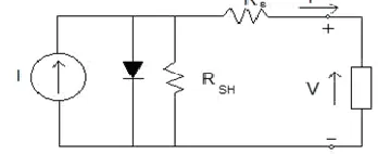
[image:2.612.328.552.303.473.2]The electrical equivalent circuit model of PV cell consists of a current source in parallel with a diode as shown in Fig. 1
Fig 1 Electrical Equivalent Circuit Model of PV Cell
A Maximum Power Tracking (MPPT) circuit, which allows the maximum output power of the PV array. A Power Factor (PF) control unit, which tracks the phase of the utility voltage and provides to the inverter a current reference synchronized with the utility voltage. A converter, which can consist of a DC/DC converter to increase the voltage, a DC/AC inverter stage, an isolation transformer to ensure that the DC is not injected into the network, an output filter to restrict the harmonic currents into the network. The MPPT algorithm, the synchronization of the inverter and the connection to the grid are discussed. Tracking the DC voltage and current allows MPP calculation which gives the inverter to function efficiently.
Fig 2: Schematic Diagram of Grid-Connected PV System
From the electrical equivalent circuit of the PV cell, PV output current (IPV) is given by
IPv=IPh-ID-ISh (1)
Where
ID= I0(e
1
)
(
kT
IpvRs
Vpv
q
) (2)And
Ish=
Rsh
IpvRs
Vpv
(3)
[image:2.612.84.258.602.673.2]International Journal of Emerging Technology and Advanced Engineering
Website: www.ijetae.com (ISSN 2250-2459,ISO 9001:2008 Certified Journal, Volume 3, Issue 9, September 2013)
214
Iph is photocurrent, I0 is diode reverse saturation current, IPV and VPV are the PV output current and voltage respectively. As the value of Rsh is very large, it has a negligible effect on the I-V characteristics of PV cell or array. Thus (1) can be simplified toIpv=Iph-I0(e
1
)
)
(
kT
IpvRs
Vpv
q
(4)For PV array consisting of Ns series and Np parallel connected PV modules, (4) becomes,
Ipv=Np{Iph-I0(e
1
)}
(
kTNs
IpvRs
Vpv
q
(5)B.PV Characteristics
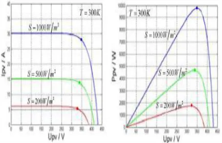
[image:3.612.327.551.143.284.2]The PV model is simulated using Solarex MSX60, 60W PV module. The simulated I-V and P-V characteristics of the Solarex PV module at constant temperature and varying insolation are shown Fig.3 respectively. It can be seen from Fig. 3 that the decrease in insolation reduces the current largely but voltage fall is small. shows that the reduction in insolation reduces the power largely as both voltage and current are decreasing. The effect of temperature on I-V and P-V characteristics of Solarex PV module is shown in Fig4. respectively. It can be seen from Fig.4 that the increase in temperature reduces the open circuit voltage largely but rise in current is very small. Fig.4 shows that the increase in temperature reduces the PV output power as the reduction in the voltage is larger than the increase in current due to temperature rise.
Fig. 3 I-V and P-V curve obtained for SOLTECH 1STH-235
Fig4:I-V and P-V curve of SOLTECH 1STH-235 at different temperatures
III. PROPOSED MPPT ALGORITHM
From the simulated I-V and P-V characteristics of the PV module, it can be seen that the characteristics are highly nonlinear. Also, there is single point on P-V curve where the PV can produce maximum power. The MPP changes with change in insolation and temperature. Therefore, an MPPT controller is required to extract maximum available power from the PV array under varying load and changing environmental conditions. This paper proposes a novel fuzzy logic based MPPT controller Fuzzy logic can model or control non-linear systems that are difficult to model mathematically. The fuzzy logic is chosen for MPPT as it gives appropriate performance for varying dynamics, higher convergence speed, robust and simple to design compared to conventional methods. The major objective of the proposed controller is to track and extract maximum power from the PV arrays for a varying solar insolation and cell temperature. The block diagram of the proposed fuzzy logic controller (FLC) is shown in Fig.4. The major functional blocks of the FLC are described as follows
[image:3.612.58.285.519.665.2]International Journal of Emerging Technology and Advanced Engineering
Website: www.ijetae.com (ISSN 2250-2459,ISO 9001:2008 Certified Journal, Volume 3, Issue 9, September 2013)
215
1) FuzzificationFrom the prior knowledge of input and output range, the fuzzification process divides the input and output into linguistic fuzzy sets. The proposed FLC takes single input that is the slope of the P-V curve and gives the duty ratio for switching the boost converter as an output. After sampling the PV array voltage and current, ΔP(k) and ΔV(k) are determined as follows:
)
1
(
)
(
)
(
P
k
P
k
P
k
(6))
1
(
)
(
)
(
V
k
V
k
V
k
(7)Where P(k) and V(k) are the power and voltage of PV array, respectively. The ΔP(k)/ΔV(k) obtained using (6) and (7) is given as an input to the FLC that generates the duty ratio (D) as an output for providing the switching pulses to the boost converter in order to operate the PV array at MPP.
2)Fuzzy rule base
The fuzzy rules should be precisely defined based on the knowledge in order to generate an output duty ratio as per the magnitude of the slope of P-V curve to operate the PV array at MPP. When the slope of P-V curve is positive then to reach towards MPP, the duty ratio of boost converter is decreased in order to increase the PV operating voltage. Similarly, if the slope of P-V curve is negative then to move the operating point at MPP, the duty ratio is increased.
3)Defuzzification
The Defuzzification process generates the single crisp value of output duty ratio (D) from the aggregated fuzzy set that includes a range of output values. The widely used centroid (centre of area) method [16] is used to convert the fuzzy subset of duty ratio (D) to real number. It computes the centre of gravity from the final output fuzzy set, and gives a result which is highly related to all of the elements in the same fuzzy set. It is mathematically represented by
z
=
dz
z
zdz
z
)
(
).
(
(8)where, z* = D which is the output of fuzzy logic controller, ∫ denotes an algebraic integration and z is the aggregated fuzzy set of output.
The proposed fuzzy logic MPPT controller applies variable steps in duty ratio for controlling the boost converter as per the current operating point and hence, gives faster convergence to MPP compared to conventional algorithms. The proposed algorithm gives robust performance under rapidly changing environmental conditions under which the conventional P&O technique is likely to fail [1].
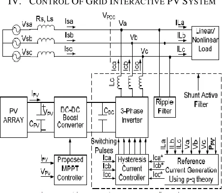
[image:4.612.327.554.244.440.2]IV. CONTROL OF GRID INTERACTIVE PV SYSTEM
Fig 6 Grid connected PV system configuration
The grid interactive PV system configuration used for simulation study is shown in Fig. 6. It consists of two power processing stages: DC-DC boost converter as first stage and three-phase voltage source inverter as second stage. The boost converter stage provides not only the boosting of PV output voltage for grid connectivity but also used as MPP tracker.
International Journal of Emerging Technology and Advanced Engineering
Website: www.ijetae.com (ISSN 2250-2459,ISO 9001:2008 Certified Journal, Volume 3, Issue 9, September 2013)
216
A.Reference Current GenerationThe reference current generator block generates the reference current to be injected into the grid upon sensing the voltage at the Point of Common Coupling (VPCC) and load currents using instantaneous active and reactive power (p-q) theory [17]. For the computation of p and q, the three phase voltages at the point of common coupling (PCC) and load currents must first be transformed to the stationary two axis (α-β) co-ordinates. The instantaneous real and reactive power p and q are determined using equations (9)-(13).
Vαβ=C
Vabc (9)Iαβ=C
ILabc (10)(11)
P = Vα×Iα + Vβ×Iβ (12)
q = Vα×Iα - Vβ×Iβ (13)
Both instantaneous power quantities p and q consists of dc and ac components. While the dc components p and q arise due to the fundamental, the ac components p and q are a result of harmonic components. In order to inject active power generated by PV obtained using the proposed MPPT controller and also to provide harmonic as well as reactive power compensation as per the load demand , the reference for active and reactive power are generated according to (14) and (15). P*=PPV+
P
~
(14)q*=q=
q
q
~
(15)The ac component is determined by first extracting
q
~
using a very low cut off low pass filter and thensubtracting it from p obtained using (12). Finally, the reference currents are generated as per (16) and (17).
B.Hysteresis Current Controller
The hysteresis current controller compares the three phase reference currents (ica*, icb*, icc*) generated using (17) with the actual inverter currents (ica, icb, icc) and generates the switching pulses as per the logic given below:
leg-a upper switch is OFF and lower switch is ON
leg-a upper switch is ON and lower switch is OFF Where, hb is the hysteresis band around the reference current which is usually 5 % of the maximum current to be injected by the inverter. Similarly, control signals for leg-b and leg-c of the inverter switches are generated.
C.Ripple Filter
The ripple filter as shown in Fig. 7 is used to absorb the switching frequency ripples. The switching ripples are generated due to switching of the inverter using the hysteresis current controller because of practical limitation in minimizing the hysteresis band and also due to switching of the boost converter. The ripple filter is a series R-C filter whose component values are so chosen as to absorb the high frequency components in multiple of switching frequency with the constraint that the fundamental current drawn by ripple filter should not exceed 5 % of the maximum load current.
D.Membership Functions & Rules
International Journal of Emerging Technology and Advanced Engineering
Website: www.ijetae.com (ISSN 2250-2459,ISO 9001:2008 Certified Journal, Volume 3, Issue 9, September 2013)
217
Fig. 7. Membership function for input variable (ΔP/ΔV)
Fig.8 Membership function for output variable (D)
The seven rules used for tracking the MPP in the proposed technique are listed in Table I.
TABLE I Fuzzy Rules
V. SIMULATION RESULTS
Here simulation results are carried out under different load conditions as well as various controlling techniques.
1). Grid Connected PV System with Instantaneous P-Q Theory based Active Power Filter. 2) Grid Connected PV System with Instantaneous D-Q Theory based Active Power Filter.
[image:6.612.322.558.186.450.2]Case 1: Grid Connected PV System with Instantaneous P-Q Theory based Active Power Filter.
Fig. 9 Matlab/Simulink Model of Proposed Compensator with Instantaneous P-Q Theory
Fig.9 shows the Matlab/Simulink Model of Proposed Compensator with Conventional DC Link Controller based with Instantaneous P-Q Theory by using MATLAB/Simulink Platform.
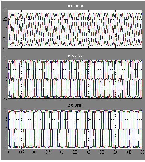
Fig. 10 Source Voltage, Source Current, Load Current without Compensator
[image:6.612.322.560.526.678.2]Fig.10 shows the Source Voltage, Source Current, Load Current without Compensator, due to non-linear diode rectifier pollutes source side current, without compensator load current is equal to source current.
[image:6.612.58.286.555.676.2]International Journal of Emerging Technology and Advanced Engineering
Website: www.ijetae.com (ISSN 2250-2459,ISO 9001:2008 Certified Journal, Volume 3, Issue 9, September 2013)
218
[image:7.612.55.290.173.379.2]Fig.11 shows the source side power factor, is not unity condition due to non-linear load, source current somewhat distorts.
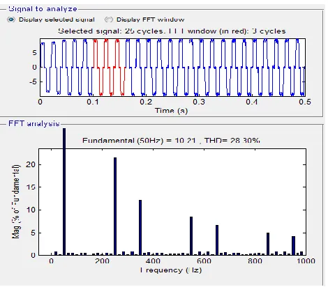
Fig.12 FFT Analysis of source current without compensator
Fig.12 shows the FFT Analysis of source current without compensator, we get THD is 28.30%.
Fig. 13 Source Voltage, Source Current, Load Current with Conventional Based Compensator
[image:7.612.324.557.188.314.2]Fig. 13 shows the Source Voltage, Source Current, Load Current without Compensator, due to non-linear diode rectifier pollutes source side current, using compensator we get sinusoidal nature.
Fig.14 Source Power Factor
Fig.14 shows the source side power factor, is unity condition due to compensator is active.
Fig.15 FFT Analysis of source current with compensator
Fig.15 shows the FFT Analysis of source current with compensator, we get THD is 4.62%.
[image:7.612.324.560.346.563.2] [image:7.612.55.288.427.609.2]International Journal of Emerging Technology and Advanced Engineering
Website: www.ijetae.com (ISSN 2250-2459,ISO 9001:2008 Certified Journal, Volume 3, Issue 9, September 2013)
[image:8.612.57.287.125.307.2]219
Fig. 16 Matlab/Simulink Model of Proposed Compensator with Instantaneous D-Q Theory
[image:8.612.320.557.128.345.2]Fig. 16 shows the Matlab/Simulink Model of Proposed Compensator with Conventional DC Link Controller based with Instantaneous D-Q Theory by using MATLAB/Simulink Platform.
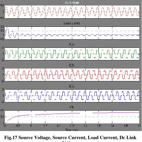
Fig.17 Source Voltage, Source Current, Load Current, Dc Link Voltage
Fig.17 shows the Source Voltage, Source Current, Load Current, Dc Link Voltage of Proposed Compensator with Conventional DC Link Controller based with Instantaneous D-Q Theory.
Fig. 18 Source Power Factor & Load Current
Fig.18 shows the source voltage as well as load currents of proposed compensator.
[image:8.612.323.559.380.649.2] [image:8.612.56.288.389.622.2]International Journal of Emerging Technology and Advanced Engineering
Website: www.ijetae.com (ISSN 2250-2459,ISO 9001:2008 Certified Journal, Volume 3, Issue 9, September 2013)
220
Fig.12 shows the FFT Analysis of source current of source current with Id-Iq Based compensator, we get THD is 1.90%.
VI. CONCLUSION
Classical “renewable energy source-based systems” are passive generators, as they produce maximal (non-dispatched) power even though this power is not useful for the grid. In this paper, multi functional grid interactive PV system is presented using a novel fuzzy logic based MPPT. The proposed MPPT controller is able to track the MPP accurately under uniformly varying as well as rapidly changing insolation and gives faster convergence as a variable step size in duty ratio is applied inherently by the algorithm and also used at our dc link controller for getting fast response. The proposed fuzzy controller maintains the dc link voltage within the limit for injecting the power into the grid. Apart from injecting active power during day time, the PV inverter also compensates the harmonics and reactive power during day time as well as at night. The simulation results validate the performance of grid interactive PV system for both active power injection as well as shunt active power filter functionality to mitigate the power quality issues thus increases the utilization factor of the system by using both the instantaneous power theories.
Acknowledgment
I am extremely thankful to GUDLAVALLERU ENGG COLLEGE Electrical & Electronics Engineering Department for providing excellent lab facilities which were helpful in successful completion of my project.
REFERENCES
[1] S. Jain and V. Agarwal , “Comparison of the performance of maximum power point tracking schemes applied to single-stage grid-connected photovoltaic systems”, IET Electr. Power Appl., vol. 1, no. 756(5), pp. 753-762, September 2007.
[2] Zue A. O., Chandra A., “Grid Connected Photovoltaic Interface with VAR Compensation and Active Filtering Functions”, International Conference on Power Electronics, Drives and Energy Systems, PEDES’06, 2006.
[3] P. Takun, S. Kaitwanidvilai and C. Jettanasen, “Maximum Power Point Tracking using Fuzzy Logic Control for Photovoltaic Systems”, International conference of engineers and computer scientists (IMECS), Vol.-II, pp. 986-990, March-2011.
[4] Chetan Singh Solanki, “Solar Photovoltaics: Fundamentals, Technologies and Applications”, PHI Learning Private Limited, New Delhi, 2009.
[5] Subiyanto, Azah Mohamed, and MA Hannan, “Hardware implementation of Fuzzy Logic based Maximum Power Point Tracking Controller for PV Systems”, The 4th International Power Engineering and Optimization Conf. (PEOCO2010), pp. 435-439, June 2010.
[6] Md. Asiful Islam , A. B. Talukdar , Nur Mohammad, P K Shadhu Khan, “Maximum Power Point Tracking of photovoltaic Arrays in Matlab Using Fuzzy Logic Controller”, Annual IEEE India conference (INDICON), 2010.
[7] B. Alajmi, K. Ahmed, S. Finney, and B. Williams, "Fuzzy Logic Controlled Approach of a Modified Hill Climbing Method for Maximum Power Point in Microgrid Stand-alone Photovoltaic System", IEEE Transactions on Power Electronics”, vol. 26, no. 4, pp. 1022-1030, April 2011.
[8] A. M. Al-Zamil, D. A. Torrey, “A Passive Series, Active Shunt Filter for High PowerApplications”, IEEE Transactions on Power Electronics, vol. 16, no. 1, pp. 101-109. January 2001
[9] H. Yu, J. Pan and A. Xiang, “A multi-function grid-connected PV system with reactive power compensation for the grid”, Solar Energy, 79, pp. 101-106, 2005.
[10] G. Tsengenes and G. Adamidis, “Investigation of the behaviour of a three-phase grid-connected photovoltaic system to control active and reactive power”, Journal on Electrical Power Systems Research (Elsevier), 81, 2011, pp. 177-184.
[11] Seo Hyo-Ryong, Jang Seong-Jae, Kim Gyeong-Hun, Park Minwon and Yu In-Keun, “Hardware based performance analysis of a multi-function single-phase PV-AF”, Energy Conversion congress and Exposition, pp. 2213-2217, 2009.